Prior Scientific PriorLab User manual

PriorLux™1

2Prior Scientific
1. Introduction
The PriorLab and PriorLux upright compound microscopes are high quality instruments
equipped with high resolution, chromatically corrected optics for excellent image quality.
The robust construction and hard wearing materials ensure long lasting and trouble free
operation. The instrument can be used with a number of accessories allowing brightfield,
dark ground, phase contrast and polarising contrast observations.
For documentation, both instruments are available with a trinocular head which permits
mounting of a video or digital camera system.
2. Unpacking
The PriorLab / PriorLux is shipped in protective bags within a pre-formed container. Each
component should be carefully unpacked and checked, cutting rather than tearing the plastic
bags. The head (binocular or trinocular) should be fitted to the dovetail on top of the stand
and locked in place with the head locking screw. The eyepieces then just drop into the
eyepiece tubes at the front of the head, these should be pushed in as far as they will go.
Remove each objective lens from its protective “pot” and screw into the free positions on
the nosepiece. Move the stage and the condenser carrier to the highest position and insert
the condenser from underneath with the diaphragm control facing to the front. This is
locked in position with the clamping screw, which is fitted from the side.

PriorLux™3
3. Specifications
PriorLab PriorLux
Eyepieces 10x 18mm field of view 10x 20mm field of view
Condenser Abbe NA 1.25 with iris
diaphragm and filter holder
Abbe NA 1.25 with iris
diaphragm and filter holder
Mechanical Stage Dimensions – 185mm x 145mm
Movement – 75mm x 55mm
Dimensions – 185mm x 145mm
Movement – 75mm x 55mm
Focusing
Mechanism
Co-axial fine and coarse
adjustment with tension control
and focus stop
Co-axial fine and coarse
adjustment with tension control
and focus stop
Viewing Head Interpupillary distance 55-
75mm
Interpupillary distance 55-
75mm
Kohler
Illumination
12V 30W halogen lamp with
variable brightness control
12V 30W halogen lamp with
variable brightness control
Power Supply 220/240 VAC 50Hz and 110
VAC 60Hz. Universal input
voltage
220/240 VAC 50Hz and 110
VAC 60Hz. Universal input
voltage
Objectives Mag. NA Tube
Length
Mag. NA Tube
Length
4x 0.12 160mm 4x 0.12
∞
10x 0.25 160mm 10x 0.25
∞
40x (S) 0.65 160mm 40x (S) 0.65 ∞
100x (S) 1.25 160mm 100x (S) 1.25 ∞
4Prior Scientific
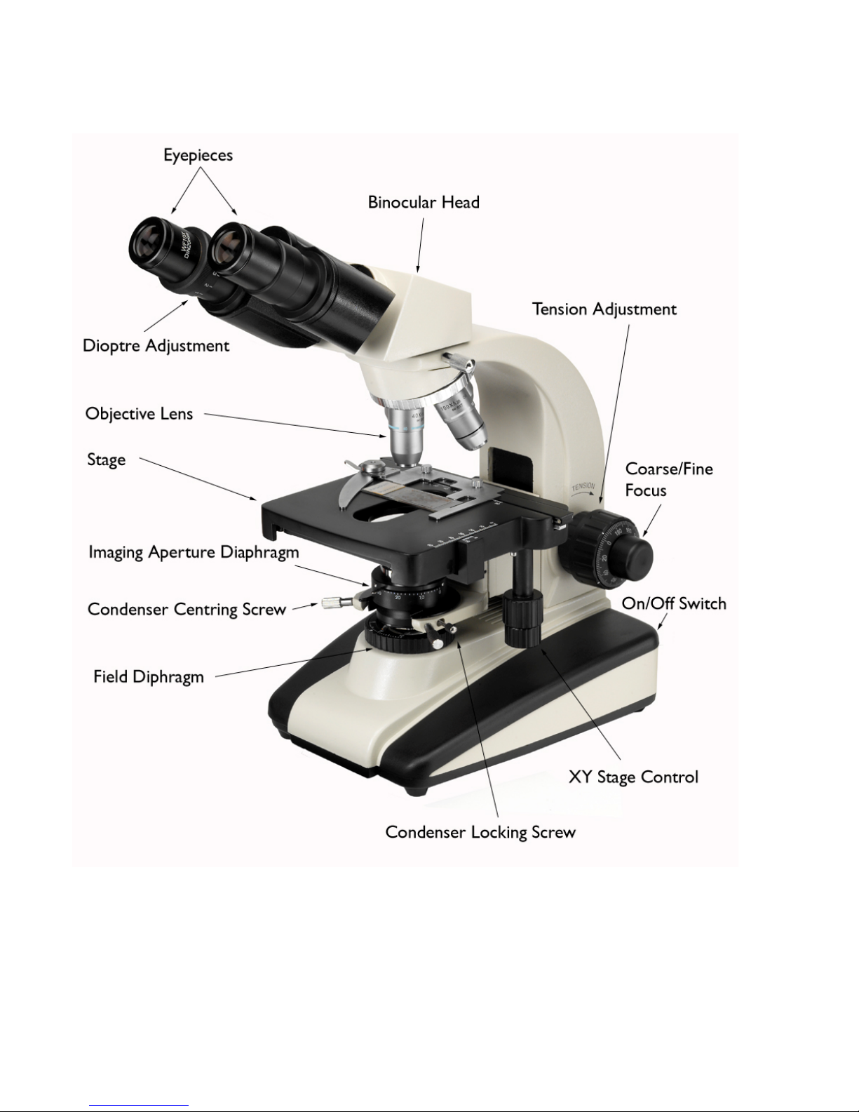
4. Component Parts

PriorLux™5
5. Electrical Connection and Safety
Stands are supplied with an operating voltage of either 220/240 VAC 50/60Hz or 110/120
VAC 50/60Hz. The instrument is supplied with a power lead complete with appropriate
plug for mains connection. UK plugs are fitted with a 3A fuse. This should only be
replaced with a similarly rated fuse. The instrument should ALWAYS be switched off and
isolated from the mains before any lamp or fuse is changed. The internal fuse is a T1.25A
type (replacement code W335). If necessary, replace only with this type of fuse.
6. Setting Up
Connect the power cable to the base of the microscope, at the rear, and before switching on
the power, reduce the lamp intensity control to its minimum setting. After switching on,
the intensity should be increased to a comfortable level. This procedure should be reversed
before switching off. Following this method will considerably prolong the life of the bulb.
Binocular/Trinocular Head
Interpupiliary distance should be set by rotating both eyepiece tubes in an arc until the two
images coincide and the view is perfectly circular to both eyes. Note the value on the scale
between the eyepieces so that the position can quickly be regained for future viewing.
Place a specimen on the stage and focus the image while looking through only the right
eyepiece. When the specimen is in focus close the right eye and adjust the dioptre on the
left eyepiece so that the image is perfectly focused. The instrument is now balanced for
your eyes.

6Prior Scientific
7. Setting Köhler Illumination
A. Follow the procedure in section 6 to set up the instrument for your eyesight.
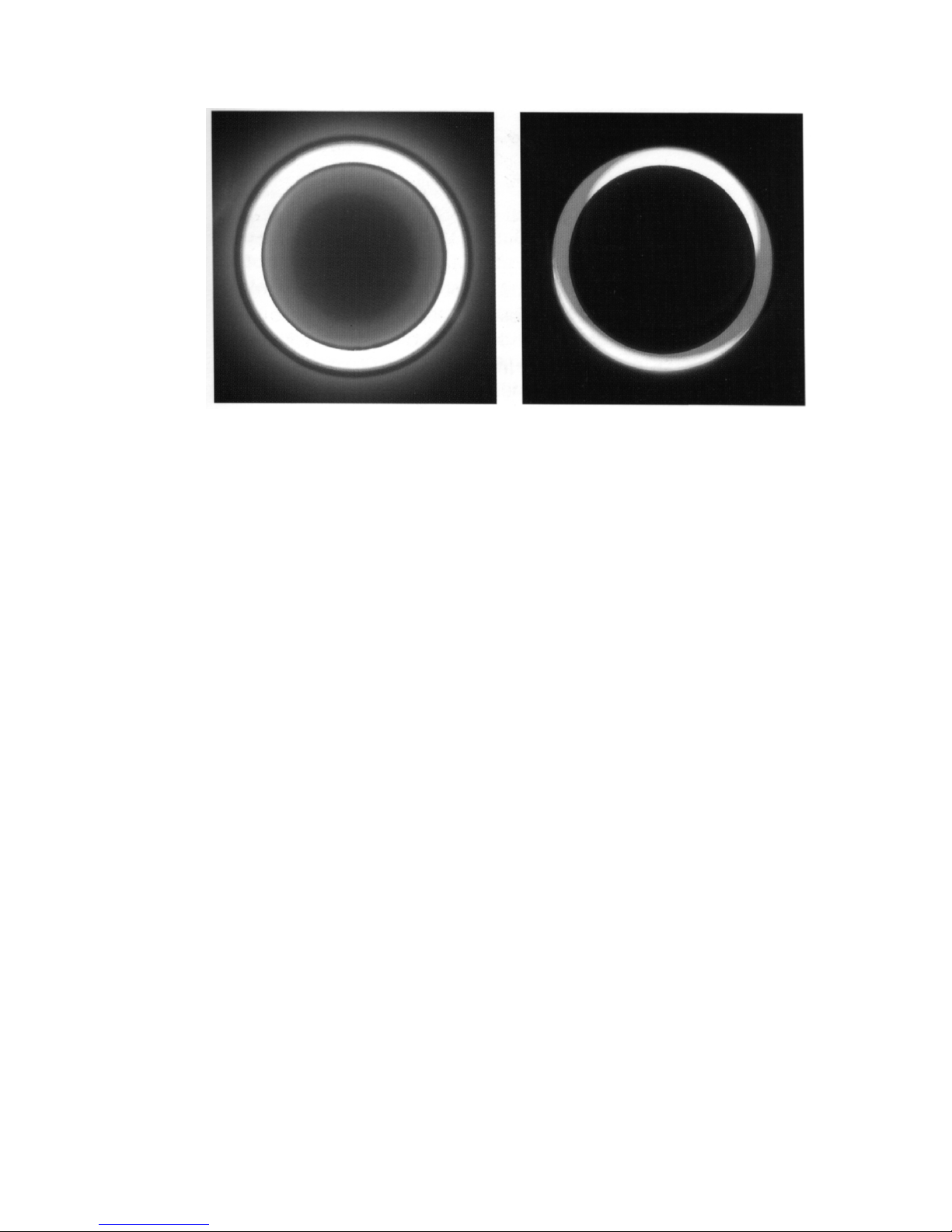
B. With a specimen in sharp focus using the 10x objective, close the field diaphragm
until it impinges on the field of view, Figure 1, Picture A.
Figure 1
C. Focus the condenser using the side mounted rack and pinion controls until the
leaves of the diaphragm are in sharp focus, Figure 1, Picture B.
D. Using the condenser centration controls move the diaphragm into the centre of the
field of view, it may help to open it until it is nearly touching the outside of the
field to attain perfect centration, Figure 1, Pictures C & D.
E. Fully open the field diaphragm.
F. Fully open the condenser diaphragm and then slowly close it until you see the
contrast within the image increase. If you then remove an eyepiece and look
directly down the tube from a distance of 20-30cm you should see an image similar
to picture D in Figure 1. The aim here is to have the “bright” area occupying
approximately 70% of the total field. The amount it occupies will change
dependant on the objective lens in use. If you have set up the instrument using the
10x objective (recommended) then as you increase the magnification this
diaphragm will need opening to optimise the contrast and resolution. Often it is set
for the objective which is either most frequently used or most critical in terms of
resolution and left in that position

PriorLux™7
G. Oil Immersion Objectives Only
For oil immersion lenses, make sure that a part of the specimen is in the centre of the
field of view as seen with the last dry objective used. Rack the nosepiece up slightly,
swing the dry lens to one side, rotate the 100x oil immersion lens over the specimen
ensuring that it clears the cover-slip. If there is insufficient clearance, rack the
nosepiece up further. Lower the lens close to the slide and then rotate it slightly to
one side. Place a drop of immersion oil (free of air bubbles) on the specimen and
gently rotate the lens into the drop. Using the fine focus knob, focus the image.
Proceed as before through steps B to F. Finally, set the focus stop to ensure that the
front lens of the objective does not touch the slide.
Remove residual oil from the objective after use.
8. Cleaning Objectives
It is critical that the front lens of each objective is kept clean and free of contamination.
Any dust or dried immersion oil will seriously affect the image quality attainable with that
objective. If contamination is suspected then the easiest way to confirm this is by removing
the objective lens and examining the front lens using the eyepiece. To do this take out one
of the eyepieces, turn it around so that you are looking the wrong way through it and move
it towards the front of the objective until you can focus on the front lens. This will clearly
show any contamination. To remove dirt and oil a lens cloth, lens tissue or cotton bud
dampened with industrial alcohol can be used. A spiral motion starting from the centre of
the lens moving to the outside is the best way of achieving a thoroughly clean surface

8Prior Scientific
9. Phase Contrast
Figure
2
Phase contrast is a technique used to amplify contrast in unstained samples. To be able to
see objects with phase contrast the optional phase kit is required. This includes a phase
turret condenser (see figure 2), phase objectives, a centering telescope and a green filter.
Firstly the standard condenser must be removed by loosening the retaining screw and the
phase turret condenser installed in its place. Swap the standard objectives (if you have
them) for phase contrast objectives, these are engraved PH, and select the correct condenser
position (0 for brightfield, 10 for the 10x objective, 20 for the 20x objective etc.) Follow
the steps in section 7 to ensure that Köhler illumination is set up properly. Remove an
eyepiece and insert the centering telescope, this allows you to focus on the phase rings and
make adjustments to their alignment. The two rings, one bright, one dark should overlap
perfectly (A), if not (B) then their position relative to one another should be adjusted using
the centration screws at the rear of the condenser (Figure 3).
To make adjustments to the phase ring alignment push in the adjustment screws and then
turn. When the alignment is complete remember to pull the screws back out or it will be
impossible to change condenser position.
PriorLux™9
A B
Figure 3
This procedure needs to be carried out for every objective, but unless deliberately adjusted
should not need checking again frequently. If the quality of the phase contrast image is
poor then check that the condenser is properly focused and centred and then ensure that the
rings are correctly aligned.
10. Dark Ground
The microscope may be used for dark ground observations if the optional phase contrast
condenser has been purchased. To use dark ground simply move the condenser position
from brightfield (O) to dark ground (D) by rotating the condenser turret.

10 Prior Scientific
11. Using a Camera
The PriorLab / PriorLux microscopes, when fitted with a trinocular head, can be used with
a range of cameras for documentation purposes. Video cameras, both analogue and digital
provide ‘moving’ pictures for more advanced imaging applications, while digital ‘still’
cameras can be used for basic image capture.
Detailed instructions for the operation of the selected video or digital camera are supplied
with the camera.
Assembly Video Cameras
A. Screw the c-mount adapter (part no. WXCM1 1.0x or WXCM050 0.5x) to the
video camera
B. Loosen the knurled silver screw on the c-mount adapter and insert the adapter
with the attached camera into the top of the photo tube on the trinocular head
C. Tighten the screw to secure the assembly
D. Connect camera to a PC, framegrabber or analogue monitor as required
E. To view the image via the camera, pull out the light path selector on the side of
the trinocular head. This diverts 80% of the light to the camera and 20% to the
eyepieces
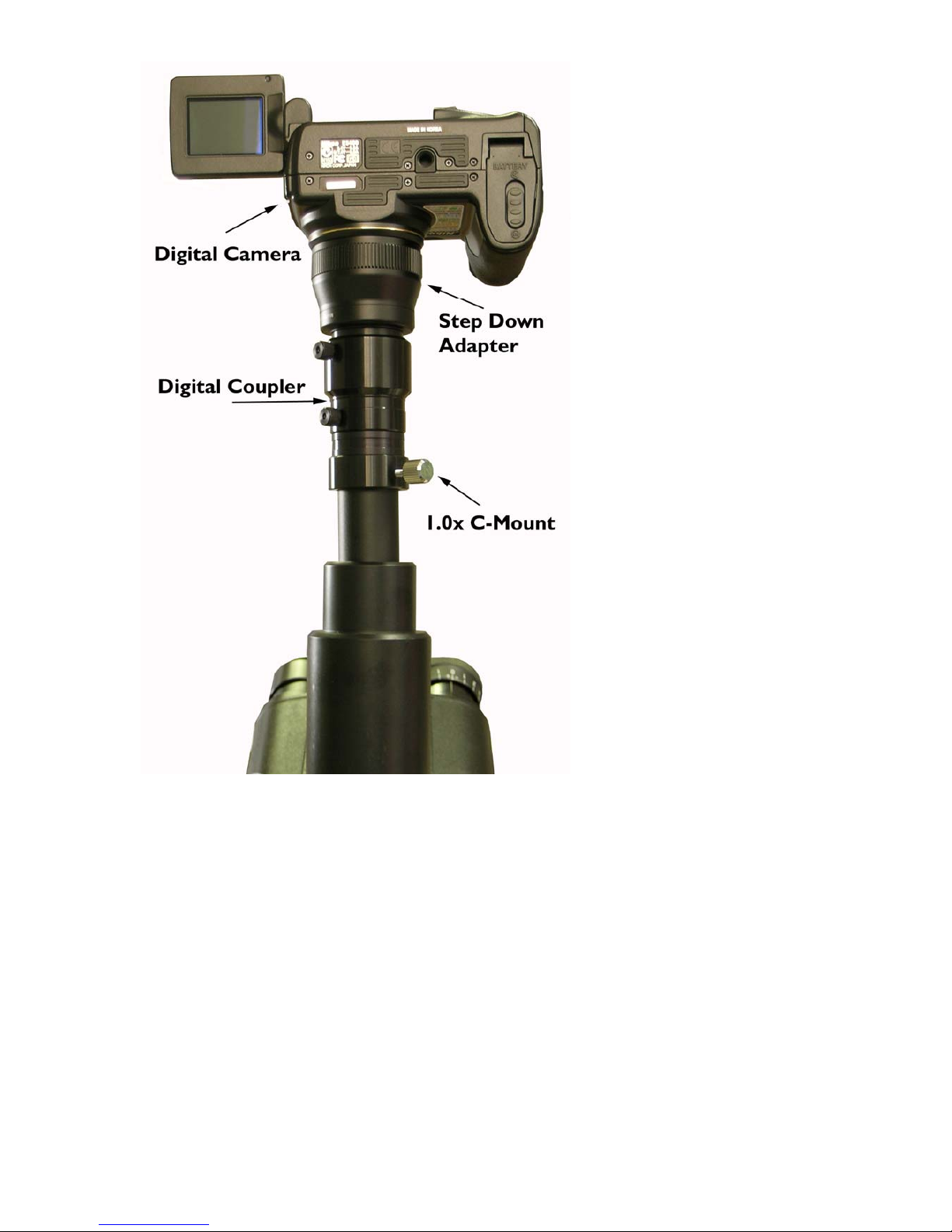
Assembly Digital Cameras
This is similar to the assembly of video cameras above, but a digital coupler (part no.
MZO1403 suitable for the Nikon Coolpix 4500 or the MZO5503 suitable for the Nikon
Coolpix 5400) and a step down ring (part no. W3000) may also be required depending on
the camera model used.
For more detailed set up information refer to the literature supplied with the camera.
PriorLux™11

12 Prior Scientific
12. Bulb Replacement and Adjustment
Halogen bulbs have a finite life and will need replacing from time to time. Replacement
bulbs, part number W3257, are available from Prior Scientific.
To change the bulb;
A. Switch off the microscope and isolate from the mains electrical supply
B. Remove the eyepieces from the viewing head to prevent them falling out
C. Lay the microscope on its back to gain access to the base plate
D. Loosen the screw which holds the lamp cover to the base plate
E. Open the lamp cover to expose the bulb holder
F. Remove the old bulb and replace it with
the correct replacement bulb (part no.
W3257, 12V 30W push fit double pin type)
by sliding upwards in its holder. Do not
handle the bulb with bare fingers, hold it in
a piece of paper tissue or in the bulb
wrapping material. Finger marks can cause
contamination which blackens the bulb
when it is switched on. If the bulb has been
touched with the fingers, clean it with a
tissue moistened with alcohol.

PriorLux™13
13. Fuse Location
The fuse is located on the base towards the front right corner of the instrument.
14. Spare Parts
W3257 – Spare bulb 12V 30W Halogen
W335 – Fuse T1.25A
15. Safety Precautions
The following symbols have been used on this microscope
These symbols are found next to the bulb access door on the underside of the
instrument.
Warning High voltage, disconnect power supply before changing the bulb.
This symbol is located next to the bulb access door on the underside of the
instrument
Caution Hot surface, allow surface and bulb to cool down completely before
attempting to change the bulb.

14 Prior Scientific
16. Regulatory Compliance
Complies to the following standards
EN/IEC 61010-1:2001 Safety requirements for electrical equipment for measurement,
control, and laboratory use – part 1: General requirements
EN61326:1997 (+A1/A2/A3) Electrical equipment for measurement, control and
laboratory use – EMC requirements
Class B emmisions
EN61326:1997 (+A1/A2/A3) Electrical equipment for measurement, control and
laboratory use – EMC requirements
General immunity
CFR 47 : 2004 class A Code of federal regulations pt 15subpart B – Radio frequency
devices – unintentional radiators

PriorLux™15
17.
Specification subject to change without notification Part No. W2968 Issue B 10/05
This manual suits for next models
1


