Saluki SFED-01 User manual
SFED-01 USB Handheld Optical Fiber End Face Microscope
User Manual
Saluki Technology Inc.

2
www.salukitec.com
Content
1. Overview..............................................................................................................................................................3
2. Structure Instructions.........................................................................................................................................3
3. Operation Instructions....................................................................................................................................... 4
4. Technical Specifications.................................................................................................................................... 8
5. Ordering Information..........................................................................................................................................8
3
www.salukitec.com
1. Overview
The SFED-01 USB handheld optical fiber end face microscope adopts high-precision optical path design and
high-speed digital image processing to carry out 200/250 times magnification imaging of the measured end
face, which is especially suitable for fine inspection of stains, scratches, dents and other end face conditions.
No need to drive, connect with the computer through USB, the detection image is stored in the computer.
Stylish appearance, lightweight and portable.
The USB handheld optical fiber end face microscope can inspect various types of fiber end faces, such as
optical device ports, optical jumpers, optical modules, optical devices, male end faces of pigtails, female end
faces in deep holes of optical adapters, etc.
Key Features
FC/SC/ST/E2000/LC/MU/MPO compatible
Support operation with computer and OTDR
200/250x magnification
Suitable for DWDM, SDH, SONET equipment and various optical fiber transmission racks, optical
switches, optical distribution boxes, etc.
Built-in digital sensor, through the USB port connected to the computer to detect optical fiber end face,
easy to do the image analysis
No need to drive, plug in the USB port to work, support for USB1.1 and USB2.0 interfaces
Pre-center positioning, image centered, clear, uniform spot.
Strong compatibility, support for driver-free installation of windows and other systems.
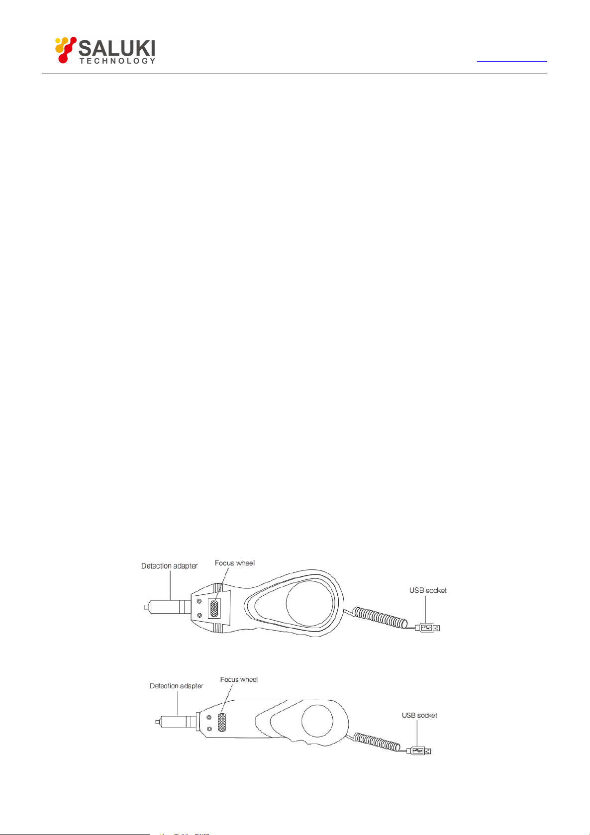
2. Structure Instructions
Handle
Fig.1 200X Image magnification
Fig.2 250X Image magnification

4
www.salukitec.com
Detection adapter
Fig.3 Adapters
3. Operation Instructions
3.1 Handle operation instruction
(1) Adjust the focus wheel
Rotate the focus wheel left and right to achieve the best clear image.
(2) Detect the adapter
Before installation, please select the suitable adapter that matches the test end surface. When installing,
please pay attention to the coaxiality of the adapter head and the handle. Screw the adapter head to the
thread of the handle head, as shown in Fig.4.
Fig.4 Correct operation
When testing, please ensure a tight and stable connection between the connector under test and the adapter.
(3) Connect the handle to the OTDR or computer
Through the USB interface, connect the microscope handle to one OTDR or computer, as shown in the Fig.5
and Fig.6.

6
www.salukitec.com
3.2 AMCAP software instruction
AMCAP software is a PC Camera application software developed by Microsoft, free of installation.
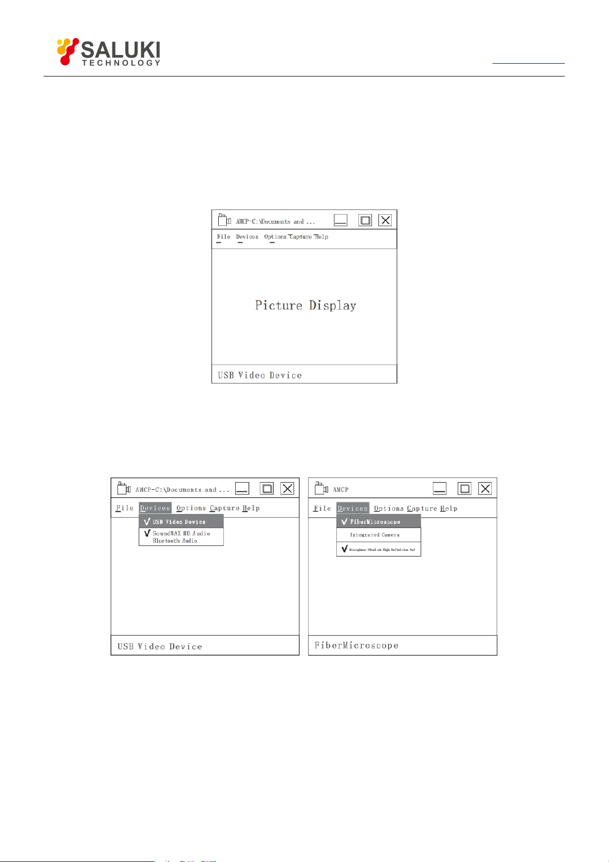
(1) Start the software
Copy the “AMCAP.EXE” file to any directory on the computer and double-click the application to start AMCAP.,
as shown in Fig.8.
Fig.8 Start the AMCAP
(2) Start the USB image device
Select "Devices" "USB Video Device" WinXP system. It is displayed as "Fiber Microscope" under WIN7
system. As shown in Fig.9.
Fig.9 WinXP and Win7 system
When multiple video devices exist in the computer at the same time, be sure to follow the steps above to
select the specified video device.
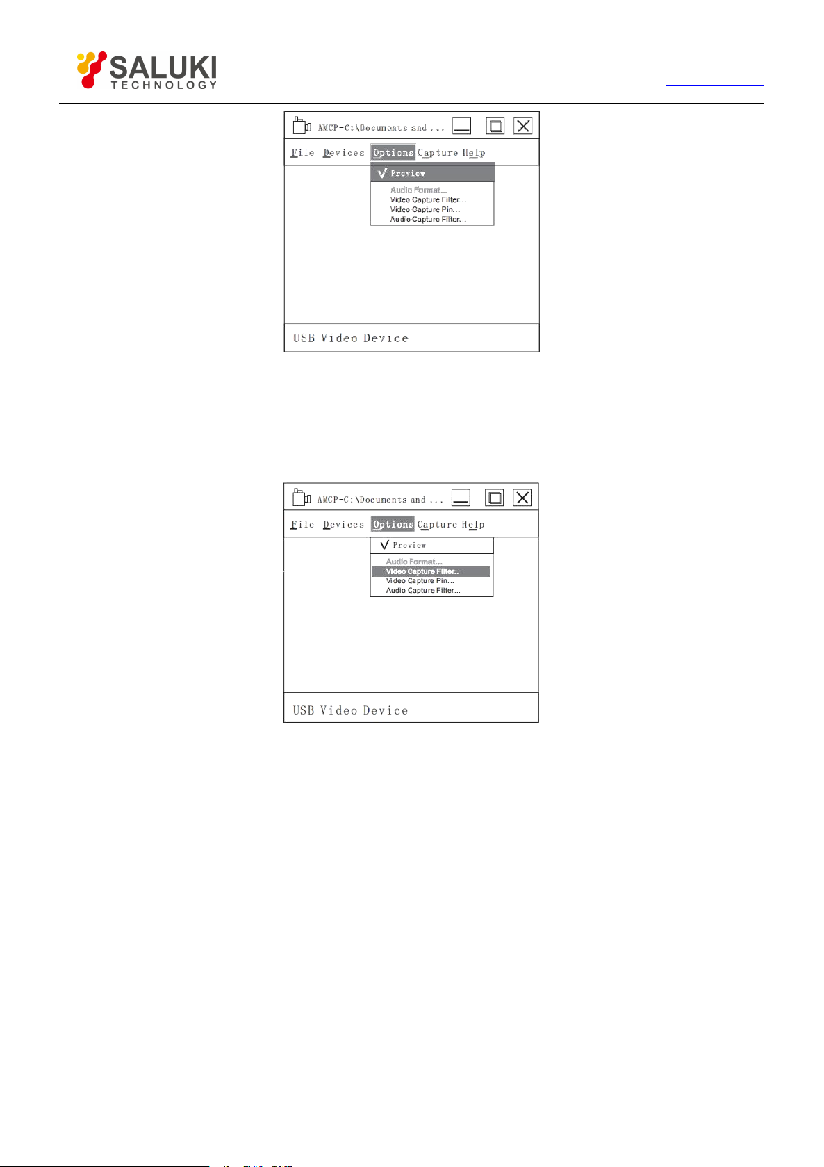
Select "Options" "Preview", as shown in Fig.10.
At this time, the USB image device is successfully started, and the image can be seen in the image
display area.
7
www.salukitec.com
Fig.10 Start the “Preview”
(3) Set image display parameters
This parameter setting can adjust the brightness, contrast, saturation and sharpness of the image.
Select “Options” and “Video Capture Filter”, as shown in Fig.11.
Fig.11 Video capture filter
You can adjust the brightness, contrast, saturation and sharpness of the image in the “ProcAmp” column
of the video.
Adjustment method: select the button corresponding to the parameter to be adjusted by the mouse, and
drag to the left or right. The corresponding parameter value is displayed in the right column. After
selecting the parameter value, click “Apply”.
To abandon the current parameter adjustment, click “Cancel” directly.
This parameter adjustment can only be applied to the current use. When the USB video device is
unplugged, it will become invalid and restore the default value.
(4) Set image resolution
There are two resolutions to choose from: 320 * 240 (default), 640 * 480
Select "Options" "Video Capture Pin", as shown in Fig.12.

8
www.salukitec.com
Fig.12 Video capture pin
Select the resolution in the "Output Size" option and click “Apply”.
To abandon the current resolution adjustment, click “Cancel” directly.
This resolution parameter adjustment can only be applied to the current use. When the USB video device
is unplugged, it will become invalid and restore the default value.
4. Technical Specifications
Focusing Style
Manual
Magnification
200/250
Resolution
0.5um
Dimensions (WxHxD)
119mm*56mm*33mm / 155mm*44mm*40mm
Weight
187g / 224g
5. Ordering Information
Standard Package
Testing handle
1 pc
Adapters
2.5mm-PC-M: 1 pc;
1.25mm-PC-M: 1 pc
SC-PC-F: 1 pc;
LC-PC-F: 1 pc
Table of contents
Popular Microscope manuals by other brands


VWR
VWR VisiScope 384 Series instruction manual

Nikon
Nikon ECLIPSE E200 POL instructions

Leica
Leica DI C800 User's manual & installation instructions

ThermoFisher Scientific
ThermoFisher Scientific Continuµm manual

ThermoFisher Scientific
ThermoFisher Scientific Continuµm manual

Olympus
Olympus SZ61 instructions