pro bel VISTEK V6301 User manual

1
VISTEK V6301AUDIO
WORDCLOCK DISTRIBUTION AMPLIFIER
USERGUIDE
www.pro-bel.com

VISTEKV6301audio
wordclock distribution amplifier
2Issue 1
Contents
1. DESCRIPTION............................................................................................................3
2. INSTALLATION..........................................................................................................4
2.1 Rear Panel Connections...................................................................................4
Table 2.1.1..........................................................................................................5
2.2 Input Impedance Selection..............................................................................5
2.3 DAMode............................................................................................................6
3. OPERATION...............................................................................................................7
3.1 Front Panel........................................................................................................7
3.2 LED Indications.................................................................................................7
3.3 Mode Controls...................................................................................................8
3.4 DART Interface..................................................................................................8

VISTEKV6301audio
wordclockdistributionamplifier
HU-V6301 3
1. DESCRIPTION
The V6301 isa broadcast qualitydistribution amplifierwhich formpart ofthe VistekV1600 range of interface
products. It is a 3U high card which isfitted into either a V1601 or V1603 rack, fromwhich it receives its
power. A passive rear module with eitherBNC or screwterminal connections, is required for all signal
interconnections.
The V6301 wordclockDA accepts two TTL level wordclock signals at 8-96kHzand distributesregenerated
TTL level wordclock to 4 outputsper channel. Modeswherebyeither one of the two wordclock inputs are
distributed to 8 AES outputs isalso available asa panel control option.
LEDs are provided to indicate signal presence on each input. No sampling rate indication is provided. The
V6301 wordclock DAmaybe used with either the balanced rear module or the unbalanced BNC module.
Two families ofpassive rear panel module are available.
• TTL inputs and outputswith screw terminals. Thisrearpanel providesfora 2:4 or 1:8 configuration.
• TTL inputs and outputswith BNC connectors. Thisrear panel provides for a (1:4 + 1:3)or 1:7
configuration, since only9 BNC connectorscan be accomodated on the rearpanel.
The V6301 allowsinput impedance to be set to either 75 or Hi-Z to facilitate daisy-chaining V6301 inputs
within a V1600 rack. Source cable runsup to 100 metresusing qualitycoaxial cable maytypicallybe
accomodated, but thisisnot guaranteed. Propagation delayofthe V6301 module is typically50ns.
The V6301 iscompatible with the VistekDARTremote system, allowing card ID, statusand mode to be
read, and card mode to be written bya DARTcompatible rackcontroller. The module can accomodate a
piggybackexpander card which expans both output groupsfrom4 to 8, providing fora maximumof16
outputs. Consult Visteksalesforfurther details.
VISTEKV6301audio
wordclock distribution amplifier
4Issue 1
2. INSTALLATION
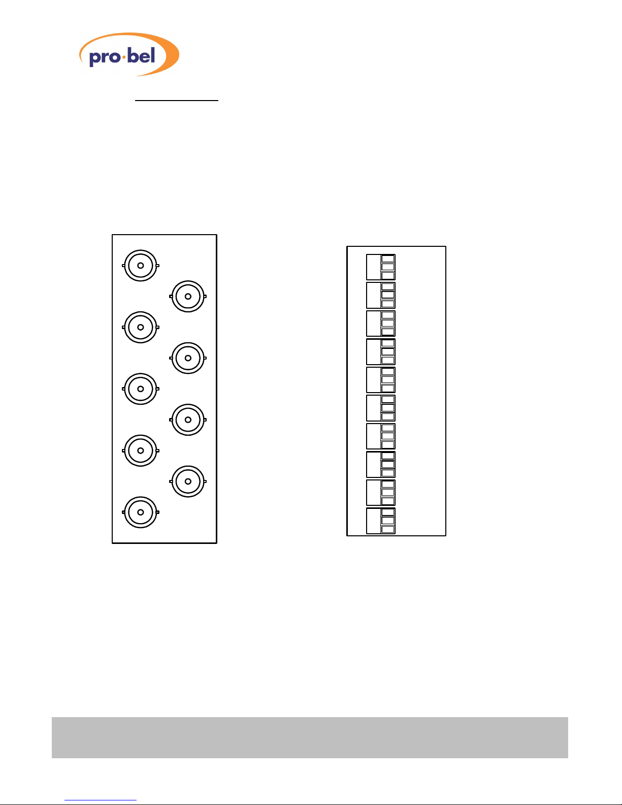
2.1 Rear Panel Connections
The 3U BNC and 3U Screw terminal rear panelsare shown below.
Note: All inputsand outputs must be connected with coaxial cable. The inputs/outputs are connected with
'hot' to the '+' terminal (centre on BNC's) and the ground to the 'S'terminal (outer GND on BNC's).
Grounds/screens are connected to chassis on alloutputs and inputs. 1U panels are similarlymarked and
details for the standard rear panel optionsare given in Table 2.1.1.
W/CLK
A (IN)
W/CLK
B (IN)
W/CLK
A1(OUT)
W/CLK
A2(OUT)
W/CLK
A3(OUT)
W/CLK
A4(OUT)
W/CLK
B1/A5(OUT)
W/CLK
B2/A6(OUT)
W/CLK
B3/A7(OUT)
W/CLK
B4/A8(OUT)
+
S
+
S
+
S
+
S
+
S
+
S
+
S
+
S
+
S
+
S
W/CLK
A (IN)
W/CLK
B (IN)
W/CLK
A1 (OUT)
W/CLK
A2 (OUT)
W/CLK
A3 (OUT)
W/CLK
A4 (OUT)
W/CLK
B1/A5(OUT)
W/CLK
B2/A6(OUT)
W/CLK
B3/A7(OUT)

VISTEKV6301audio
wordclockdistributionamplifier
HU-V6301 5
Table 2.1.1
Description ofV6301 rear panelconnections for standard rear panels
SIGNALSOURCE COMMENTS
POWER Rack PWR Header +15V at 100mA (1.5Wmax)
DARTbusRack DARTheader VistekDARTRackcontroller
W/CLK A(IN)W/CLK ext. source Ch. A TTL wordclock input:
75 /Hi-Z single ended on BNC rear panel
75 /Hi-Z single ended on screw terminal rear panel
W/CLK A1 (OUT)V6301 DA Ch. A TTL wordclockoutputs(all modes)
W/CLK A2 (OUT)75 /Hi-Z single ended on BNC rear panel
W/CLK A3 (OUT)75 /Hi-Z single ended on screw terminal rear panel
W/CLK A4 (OUT)
W/CLK B(IN)W/CLK ext. source Ch. TTL wordclockinput sourcing cable length up to 50m
75
single ended on BNC rear panel
75 /Hi-Z single ended on BNC rear panel
75 /Hi-Z single ended on screw terminal rear panel
W/CLK B1/A5 (OUT)V6301 1:8 mode: Ch A wordclocko/p.
W/CLK B2/A6 (OUT)2:4 mode: Ch B wordclocko/p
W/CLK B3/A7 (OUT)75 /Hi-Z single ended on BNC rear panel
W/CLK B4/A8 (OUT)75 /Hi-Z single ended on screw terminal rear panel
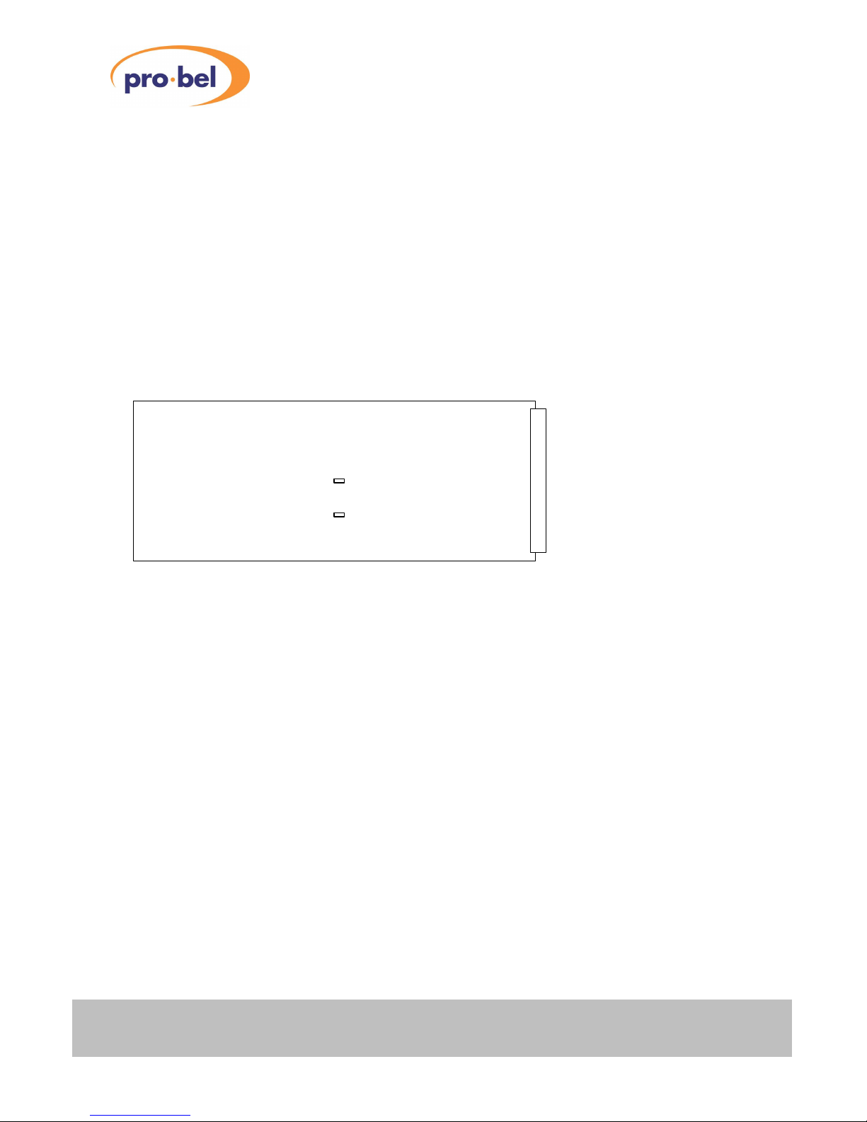
2.2 Input Impedance Selection
The input impedance ofthe A Channel and B Channel wordclock receivers maybe set to either75 ohmsor
high impedance (≥10k ) bymeansof jumpers LK3 and LK5. The high impedance function maybe used
when it desired to daisy-chain the inputs ofa number ofV6301 DA’sin a rack, without cascading them. In
thiscase one ofthe V6301s is set for 75 ohms and the others are set to high input impedance. Two
cautions are advised:
• The V6301 with 75 impedance should be the V6301 physicallyfarthest fromthe feeding source.
• The daisychaining is intended to be used within a rack orcabinet. Long cable runs into high impedance
are NOT recommended. When daisychaining V6301swith Hi-Z inputs, source cable length should not be
more than a couple of meters.
Impedance option Jumpers
Channel A 75 LK3 CLOSED
Channel A Hi-Z (>10k )LK3 OPEN
Channel B 75 LK5 CLOSED
Channel B Hi-Z (>10k )LK5 OPEN
VISTEKV6301audio
wordclock distribution amplifier
6Issue 1
2.3 DAMode
The V6301 DAhas 4 modes op operation, controlled byDARTor front panel switches. When the REM/LOCAL
switch isset to LOCAL, control is bypanel switches. Four possible modes, namelytwo 2:4 modesand two 1:8
modesas follows:
• Aout switch sourcesthe 4 Channel A outputs fromeitherthe Channel A input or the Channel B input.
• Bout switch sources the 4 Channel Boutputs fromeitherthe Channel A input or the Channel Binput.
The source channel foreach of the Aout and Bout switches isindicated byan Aor BLED above the switch.
The LEDsindicate the source channel selection in force, set either byDART(Rem/Local = Rem) or bythe
Aout and Bout switches(Rem/Local =Local). Ifthe Rem/Local switch is set to Rem, the settingsof the
Aout and Bout switchesare ignored.
The figure belowshows the V6301 and the location of the jumpers referred to in Section 2.1.
Front Panel
Rear Connector
LK3
LK5
VISTEKV6301audio
wordclockdistributionamplifier
HU-V6301 7
3. OPERATION
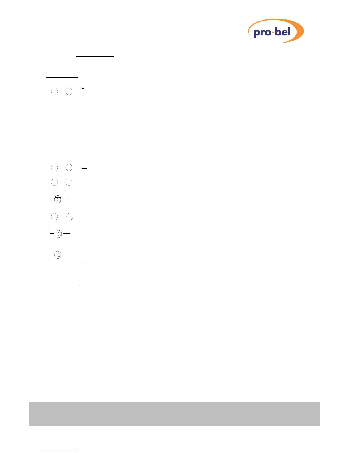
3.1 Front Panel
REM +V
V6301
Audio
W/CLK DA
RemoteControlAccess and Power indicators
ERRORindicators
ERROR
AB
B
B
A
A
Aout
Bout
RemLocal
MODEcontrols
3.2 LED Indications
The V6301 has front panel indicators asshown above.
A red ERROR LED for each channel indicates no signal on the W/CLK input.
The REM LED flashes to indicate a DARTbus accessisin progress.
The green V+ LED is lit whenever powerisapplied and the V6301’sinternal power supplyis operating
correctly.
The LEDs Aand Babove the Aout and Bout switches indicate the source channel for each ofthe output
blocks Aout and Bout, selected byeither the Aout and Bout switches, or byDART.

VISTEKV6301audio
wordclock distribution amplifier
8Issue 1
3.3 Mode Controls
The V6301 has two input channels Ain and Bin and two groupsof fouroutput channels Aout and Bout. The
mode controls Aout and Bout alloweach ofthe two groups offour output channels to receive signal from
either the Ain or Bin inputs. The Aout and Bout mode controls are onlyeffective ifthe Rem/Local switch is
set to Local. Ifthe Rem/Local switch is set to Rem, the Aout and Bout groupshave their sourcing controlled
byDART. The switchesmaybe changed at anytime and the table below showsthe possible combinations:
Aout switch Boutswitch Mode
AA1:8 mode: Aout = Ain, Bout = Ain
AB2:4 mode: Aout = Ain, Bout = Bin
BA2:4 mode: Aout = Bin, Bout = Ain
BB1:8 mode: Aout = Bin, Bout = Bin
3.4 DART Interface
The V6301 isa Class 4 DARTmodule with a serial EEPROM for reading and writing card details through the
DARTbus. In addition the unit presentstwo bytes ofstatusinformation to the DARTsystemand the DART
systemcan write one byte ofcontrol data to the V6301. Full detailsof the bit allocationsmaybe found in
document number scsm6301.doc.
Table of contents
Other pro bel Amplifier manuals


Popular Amplifier manuals by other brands

Nuvo
Nuvo Grand Concerto NV-I8GMS installation guide

Comtech EF Data
Comtech EF Data KPA-080 Installation and operation manual

SWR
SWR BASS 750 owner's manual

EA3GCY
EA3GCY QPA-1 Assembly manual

Harman Kardon
Harman Kardon The Prelude PC-200 Operating and service instructions

Chord
Chord Mojo operating instructions


