pro bel V1630 Owner's manual

30November,2006 V1630OP1/ Issue6 Page1of 8
V1630
AES-EBU DISTRIBUTIONAMPLIFIER
Applicable to Assy130-1210 ISSUEB
INSTALLATION andOPERATION
Pro-Bel Ltd
DaneHill
LowerEarley
Reading RG64PB
ENGLAND
Tel. +449866123
Fax. +449755787

Page2of 8 V1630OP1/ Issue6 30November,2006
Thispageis intentionally left blank

30November,2006 V1630OP1/Issue6 Page3of 8
V1630 AES-EBUDISTRIBUTIONAMPLIFIER
INSTALLATION ANDOPERATION
1.DESCRIPTION
TheV1630isabroadcastqualityAES-EBUdigital audiodistributionamplifierwhichformspartofthe
VistekV1600 rangeofinterfaceproducts.It isa3UhighcardwhichisfittedintoeitheraV1601or
V1603rack,fromwhichitreceivesitspower.ApassiverearmodulewitheitherBNC orscrewterminal
connections,isrequiredforallsignal interconnections.
TheunitacceptstwoAESaudio datastreamsof32kHz,44.1kHz,48kHzor96kHzand distributes
reclockedandregeneratedAES datastreamsto4AESoutputsperchannel.Modeswherebyeither
one ofthetwoAESinputsaredistributedto8AES outputsisalsoavailable asapanelcontrol option.
TheV1630canaccomodateapiggyback expandercardwhichexpansbothoutputgroupsfrom4to8,
providingforamaximumof16outputs.ConsultVisteksalesforfurtherdetails.
Twofamiliesofpassiverearpanel moduleareavailable:
· AESinputsand outputstoAES3-1992 (110Wbalanced)withscrewterminals.Thisrearpanel
providesfora2:4or1:8configuration.
· AESinputsandoutputstoAES3id-1995(75Wsingle ended)withBNCconnectors.Thisrearpanel
providesfora(!:4+1:3)or1:7configuration,sinceonly9BNCconnectorscanbeaccomodated on
the rearpanel.
TheV1630hasapassiveequaliserwhichisjumperselectable oneachAES inputandoperationis
guaranteedovercablelengthsofup to250 metres(at fs £48kHz).Typically,muchlongercable runs
upto1000metresmaybeaccomodated, butthisisnotguaranteed.
· Inputcable length0-100m: Equaliserout
· Inputcable length100m+: Equaliserin
Inputimpedancemaybesettoeither110/75 WorHi-Ztofacilitatedaisy-chaining V1630 inputswithina
V1600rack.
Thesamplingrateofeachchannel isdisplayedbymeansoffrontpanel LEDsandanERRORLEDis
providedtoindicatechannelerrors/noinput.Frontpanelswitchesallowthecardoperating mode tobe
setandLEDsprovide visual indicationofthemode.The V1630iscompatiblewiththe VistekDART
remotesystem,allowing cardID,statusandmodetoberead, and cardmodetobewrittenbyaDART
compatiblerack controller.
Note: Thismanualapplies toV1630Assy130-1210IssueB,whichhavedifferent
functionalityandpinoutconnectionstopreviousissues.Theyarenotplug-in
replaceablein thesameRearPanel assembliesused withpreviousissues.

Page4of 8 V1630OP1/ Issue6 30November,2006
2.INSTALLATION
2.1REAR PANELCONNECTIONS
The3UBNC and3UScrewterminal rearpanelsareshownbelow.Grounds/screensareconnectedto
chassisonalloutputsand inputs.1Upanelsaresimilarlymarkedanddetailsforthestandardrearpanel
optionsaregiven in Table 2.1.1.TheV1630mayalsobeorderedwitharearpanel having D-type
connectors. Thepinout of theD-connectorsareshownin Table 2.1.3.
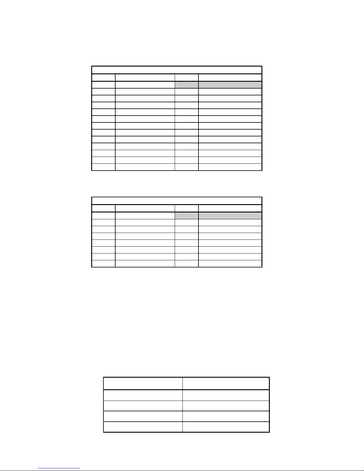
Table2.1.2
Description ofV1630rearpanelconnectionsforstandardrearpanel assemblies
SIGNAL SOURCE COMMENTS
POWER Rack PWRHeader +15Vat 170mA(2.55Wmax)
DARTbus Rack DARTheader VistekDARTRack controller
AESA(IN) AESexternalsource Ch.Ainput:
sourcingcablelengthupto250m
75Wsingle endedon BNCrearpanel
110Wbalanced onscrewterminalrearpanel
Sourcingcable lengthupto250m
75Wsingle endedon BNCrearpanel
110Wbalanced onscrewterminalrearpanel
AESA1(OUT) V1630DA Ch.Aoutputs(allmodes)
AESA2(OUT) Driving cable lengthupto250m
AESA3(OUT) 75Wsingle endedon BNCrearpanel
AESA4(OUT) 110Wbalanced onscrewterminalrearpanel
AESB(IN) AESexternalsource Ch.Binput
sourcingcablelengthupto250m
75Wsingle endedon BNCrearpanel
110Wbalanced onscrewterminalrearpanel
Sourcingcable lengthupto250m
75Wsingle endedon BNCrearpanel
110Wbalanced onscrewterminalrearpanel
AESB1/A5(OUT) V1630 1:8mode:ChAo/p. 2:4mode: ChBo/p
AESB2/A6(OUT) Driving cable lengthupto250m
AESB3/A7(OUT) 75Wsingle endedon BNCrearpanel
AESB4/A8(OUT) 110Wbalanced onscrewterminalrearpanel
AES
A (IN)
AES
B
(IN)
AES
A1
(OUT)
AES
A2
(OUT)
AES
A3 (OUT)
AES
A4 (OUT)
AES
B1/A5
(
OUT)
AES
B2/A6
(
OUT)
AES
B3/A7(OUT)
AES
A
(IN)
AES
B
(IN)
AES
A1
(OUT)
AES
A2
(OUT)
AES
A3
(OUT)
AES
A4
(OUT)
AES
B1/A5
(OUT)
AES
B2/A6
(OUT)
AES
B3/A7
(OUT)
AES
B4/A8
(OUT)
+
S
-
+
S
-
+
S
-
+
S
-
+
S
-
+
S
-
+
S
-
+
S
-
+
S
-
+
S
-
30November,2006 V1630OP1/Issue6 Page5of 8
Table2.1.2
DescriptionofV1630rearpanel connectionsforstandard rearpanelassemblies
D25FOutputconnector
Pin Signal Pin Signal
1 AESA1out-
2 GND 14 AES A1out+
3 AESA2out- 15 GND
4 AESA3out- 16 AES A2out+
5 AESA4out- 17 AES A3out+
6 GND 18 AES A4out+
7 GND 19 GND
8 AESB1out- 20 GND
9 AESB2out- 21 AES B1out+
10 AESB3out- 22 AES B2out+
11 AESB4out- 23 AES B3out+
12 GND 24 AES B4out+
13 GND 25 GND
D15FInputconnector
Pin Signal Pin Signal
1 AESAin-
2 GND 9 AES Ain+
3 GND 10 GND
4 GND 11 GND
5 GND 12 GND
6 GND 13 GND
7 AESBin - 14 GND
8 GND 15 AES Bin+
2.2INPUTIMPEDANCESELECTION
TheinputimpedanceoftheAChannel and BChannel AES receiversmaybesettoeither110/75
ohms,orhighimpedance(³10kW)bymeansofjumpersLK3and LK5.Thehigh impedancefunction
maybeusedwhenitdesiredtodaisy-chain theinputsofanumberofV1630DA’sin arack,without
cascadingthem.Inthiscaseoneofthe V1630sisset for110/75 ohmsandthe othersaresettohigh
inputimpedance.Twocautionsareadvised:
· TheV1630with110/75 impedanceshould betheV1630physicallyfarthestfromthefeeding
source.
· Thedaisy chainingisintended tobe usedwithin arack orcabinet.Long cable runsintohigh
impedanceareNOTrecommended.WhendaisychainingV1630s,sourcecable lengthshould
not be morethan acoupleof meters.
Impedanceoption Jumpers
ChannelA110/75 WLK3CLOSED
ChannelAHi-Z LK3OPEN
ChannelB110/75 WLK5CLOSED
ChannelBHi-Z LK5OPEN

Page6of 8 V1630OP1/ Issue6 30November,2006
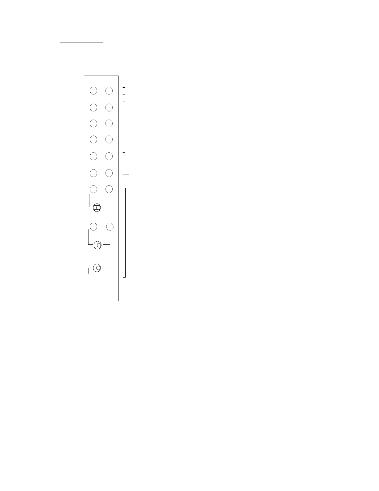
2.3INPUTEQUALISATION
TheinputequalisersontheV1630should be usedwheneverthe sourcecable lengthisgreaterthan90-
100m. Thetwoinput channels(A andB)haveindependentequalisers,eachof whichisassociatedwith
twojumpersasshownin thetable andthefigurebelow.Jumpercombinationsotherthanthoseshown
shouldnot be used.
Equaliser Jumpers
ChannelAequaliserOFFLK1andLK2CLOSED
ChannelAequaliserON LK1andLK2OPEN
ChannelBequaliserOFF LK4andLK6CLOSED
ChannelBequaliserON LK4andLK6OPEN
2.4DAMODE
TheV1630DAhas4modesopoperation,controlled byDARTorfrontpanel switches.When the
REM/LOCAL switchissetto LOCAL,control isbypanelswitches.Fourpossiblemodes,namelytwo2:4
modesandtwo1:8modesasfollows:
· Aoutswitch sourcesthe4Channel AoutputsfromeithertheChannel AinputortheChannelB
input.
· Boutswitch sourcesthe4Channel BoutputsfromeithertheChannel AinputortheChannelB
input.
Thesourcechannel foreachoftheAoutandBoutswitchesisindicatedbyan Aor BLEDabovethe
switch.The LEDsindicatethesourcechannelselection in force,seteitherbyDART(Rem/Local =
Rem)orbythe Aout and Bout switches(Rem/Local =Local).If the Rem/Local switchissetto Rem,
thesettingsofthe Aout and Bout switchesareignored.
ThefigurebelowtheV1630andthelocationofallthejumpersreferredtoinSection2.1..2.3.
Front Panel
RearConnector
LK1
LK2 LK3
LK6
LK5
LK4
30November,2006 V1630OP1/Issue6 Page7of 8
3.OPERATION
3.1FRONTPANEL
REM +V
V1630
AES AUDIO
DA
A
RemoteControl Access and Power indicators
ERROR indicators
Sampling rateindicators
B
32kHz
44.1kHz
ERROR
48kHz
A
A
A
B
B
B
96kHz
AB
B
B
A
A
A out
B out
Rem Local
MODEcontrols
3.2LED INDICATIONS
TheV1630hasfront panelindicatorsasshownabove. Eachchannel hasasetof fouryellowLEDsfor
sample rateindication.Thesampleratemustbe within4%of thenominal fortheindicatorstofunction
correctly.TheV1630cansupportnon-standardsample ratesin therange32kHz-96kHz,butthe LED
indicatorswillnotbelitatotherthan theindicated rates.
Ared ERROR LEDforeachchannel indicatesnoinput,PLLunlocked,parityerrororbiphasecoding
violationon theAES input. TheLEDsflashfor0.8secondsondetection ofindividual errors,orburn
continuouslyiferrorsoccurmorefrequentlythan 0.8sapart.
The REM LEDflashestoindicateaDARTbusaccess isinprogress.
Thegreen V+ LEDislitwheneverpowerisappliedandtheV1630’sinternalpowersupplyisoperating
correctly.
TheLEDs Aand Babovethe Aout and Bout switchesindicatethesourcechannel foreachofthe
outputblocksAout andBout,selected byeitherthe Aout and Bout switches,orbyDART..

Page8of 8 V1630OP1/ Issue6 30November,2006
3.3MODECONTROLS
TheV1630 hastwoAESinputchannelsAin andBinandtwogroupsoffouroutputchannelsAout
andBout. Themodecontrols Aout and Bout alloweachof the twogroupsoffouroutputchannels
toreceivesignal fromeitherthe Ain orBin inputs.The AoutandBoutmodecontrolsareonly
effectiveifthe Rem/Local switchissetto Local.If the Rem/Local switchissetto Rem,theAout
andBoutgroupshavetheirsourcing controlledbyDART.Theswitchesmaybe changedatany
timeandthetable belowshowsthepossiblecombinations:
Aoutswitch Boutswitch MODE
A A 1:8mode: Aout= Ain, Bout =Ain
A B 2:4mode: Aout= Ain, Bout= Bin
B A 2:4mode: Aout= Bin, Bout =Ain
B B 1:8mode: Aout= Bin, Bout =Bin
3.4DARTINTERFACE
TheV1630isaClass 4DARTmodule withaserial EEPROMforreadingandwriting carddetails
throughtheDARTbus. InadditiontheunitpresentstwobytesofstatusinformationtotheDARTsystem
and theDART systemcanwriteonebyteof control datatothe V1630.Fulldetailsof thebitallocations
maybefoundin document number scsm1630.doc.
*****
Table of contents
Other pro bel Amplifier manuals


Popular Amplifier manuals by other brands


Vanco
Vanco Pulse Audio PA230WP manual

Rose electronics
Rose electronics RA280 owner's manual

Soundstream
Soundstream Picasso PCA2.130 Owner's manual and installation guide

Bryston
Bryston BP4 Schematic diagram

Bluestream
Bluestream NPA100DA Quick reference guide

MILBANK
MILBANK MMTS301SYS Owners & installation manual


