Pro Co Sound Momentum MO8ME User manual

Mix Engine with mrc (The “Tweak”) Unit
Manual
mo8me
Pro Co Sound, Inc.
225 Parsons Street | Kalamazoo, MI 49007
1-888-253-7360 | www.procomomentum.com

2
Momentum mo8me Manual
Pro Co Sound guarantees Momentum for five years, any excuse, even abuse. If you need to return the
Momemtum unit(s), ship them to Pro Co Sound in the original carton or a suitable shipping container via
insured freight. Pro Co will return the Momentum unit(s) to you, free of charge including return postage.
Once out of Warranty, Pro Co also offers service on all its products.
Customer Responsibility:
Please read the owner’s manual thoroughly before operating the system. Complete the Warranty Card
within ten days after receipt of your Momentum system. Mail the card to us or register your product on line
at www.procomomentum.com.
The Warranty is subject to the following conditions:
1. Pro Co Sound or its authorized representative or dealer must perform all warranty servicing of the
units, otherwise all aspects of this warranty are void.
2. All tamper-proof seals on the unit(s) must be intact in order for the unit(s) to be serviced as a
warranty claim.
How obtain Warranty services:
If, after following all of the operating instructions in this manual, you find that service or support is still
needed:
1. First contact the dealer or contractor from which you purchased your Momentum product for help.
2. If your problem is not resolved after contacting your dealer, call Pro Co Sound at 1-800-253-7360 and
ask for Momentum Service. Our hours are 8:00 a.m. to 6:00 p.m. EST, Monday through Friday.
If the problem cannot be resolved remotely, Pro Co Sound may, at its discretion, advance the replacement
of the defective unit(s) and at that time provide a Return Authorization # by which the defective unit(s) can
be returned for credit or repair.
Warranty
Revision Date: 2/9/2008

3
Momentum mo8me Manual
Table of Contents
2
Warranty
Safety Precautions
Welcome
Thank You
Unpacking
Chapter 1: Overview
Momentum System
Features
Description of mo8me
The mo8me
The mo8me Enclosure
Front & Rear Panel
Contractor Panel
mcr (The Tweak)
Chapter 2: Connection and Startup
Power
Network Wiring
Copper Wiring
Copper Connection
Fiber Connection
Network Configuration
Setup
Network Clock Sync
Using the Control Panel
Setting Device
Start Channel
IP Address
Sample Rate
Chapter 3: Control Panel Functions
F1 and F2 Functions
Description of Functions
15
15
16
4
6
8
9
9
5
5
5
6
6
7
6
9
11
11
12
13
13
13
14
14
14
14
10
11
11
11
Chapter 4: The Tweak:
Overview & Set Up
Overview
Powering Up
Opening Screen
Communications Time Out Screen
Main Menu Screens
Set Up Menu
Description of Setup Menu
Setting the Routing
Connection to a mo8me
Selecting Mono or Stereo Mode
Selecting Default Mix & Master User
Setting Time-out & Back Light
Assigning Your Tweak an ID
Naming Your Tweak
Chapter 5: The Tweak:
Mixing
Main Mix Menus
Select Mix Menu
Master Mix Menu
Channel Mix Menu
Setting Your Out Channel Master Mix
Setting Input Channel Levels
Adjusting Volume Levels
Adjusting EQ Levels
Setting Panning for Stereo Channels
Selecting a Solo Channel
Muting a Channel
Naming Input Channels
Saving Mixes
Recalling Mixes
Chapter 6: mo8me Specifications
21
21
21
24
22
22
23
25
24
18
19
19
20
20
18
26
26
34
26
27
29
29
30
30
31
31
32
33
28
29
26

4
Momentum mo8me Manual
1. Read these instructions carefully.
2. Retain these instructions for future reference.
3. Heed all warnings.
4. Follow all instructions.
5. Do not use any part of this apparatus near water.
6. Do not block any ventilation openings.
7. Do not install near any heat source.
8. Do not defeat the safety purposes of the polarized or grounding type plugs.
9. Do not use the Momentum power supply for any purpose other than stated in this manual.
10. Only use Pro Co recommended accessories with any Momentum device.
To reduce the risk of fire or electrical shock, do not expose
any part of your Momentum System to rain or moisture.
To reduce the risk of electrical shock, do not remove cover. There are no
user serviceable parts inside. Refer servicing to service personnel.
Always follow the basic precautions listed below to avoid the possibility of physical injury to
you or others, or damage to the device or other property. These precautions include, but are
not limited to, the following:
Use Extreme Caution!
Before making adjustments to your Momentum system, be aware that certain actions could possibly
damage your hearing and/or the audio system itself. Think through your actions and the possible
ramifications of your adjustments. Proceed with caution and follow these important Safety Instructions:
Safety Precautions

5
Momentum mo8me Manual
Thank you for your recent purchase of the Pro Co Momentum mo8me. We hope you find our product
to be versatile and flexible. The entire line of Momentum products was designed with the intention of
offering optimal flexibility for a multitude of applications.
Pro Co Sound, a Michigan based business, was founded in 1974. We build audio interface products,
in-ear monitor controllers and facility distribution systems. We continue to live by our mission;
“Tobecomeourcustomers’verybestpartner,bybuildingaworldclassorganization,throughcontinual,
rapid improvement in all that we do, and to share in the successes and failures of our efforts.”
Welcome to the Pro Co Family.
When receiving your Momentum System, please check all cartons for damage. If there is damage,
notify the shipper and dealer in that order. Before removing any components of your Momentum
System from the shipping cartons, be sure that the order is complete as expected. Do this by
checking each Momentum System component on your packing slip to be sure it matches the number
of packing boxes and the specific type and number of components contained within. Fill out the
warranty cards and send them in! You should find the following in the carton:
1 x mo8me 1 x Antenna*
2 x Rack Ears 1 x One Spot Power Supply
2 x Stage Boots (optional) 1 x mrc (the Tweak)
Welcome
Thank You
Receiving Your Momentum mo8me
NOTE: Stage boots may be requested, for no additional charge at time of order.
* Antenna is left unattached to prevent possible damage during shipping. It will need to be
attached after delivery.

6
Momentum mo8me Manual
The Momentum network uses standard Gigabit Ethernet technology. With using standard Ethernet
technology, the Momentum system can be setup and controlled using standard Ethernet products.
Chapter 1
Overview
M
omentum
Sy
stem
Fea
t
u
r
es
The Momentum digital snake system by Pro Co is designed to replace traditional analog audio wiring
anywhere audio distribution is needed. By capturing audio at the source, converting it to digital audio
and distributing it over a standard Ethernet network, many of the difficulties in executing the increasingly
complicated audio systems of today can be simplified. By reducing the amount of field terminations,
installation becomes less time consuming. Texas Instrument, Burr Brown mic preamps and Cirrus Logic
digital converters provide a platform that is as close to analog as possible without the inherent problems
that are associated with traditional wiring.
Flexibility and expandability are enhanced through the use of modules for inputs, outputs and DSPs.
Signal routing becomes as easy as clicking a button. You can place inputs, outputs, DSPs and controls
anywhere on the Momentum network. Also digital interfaces are available for seamless system integration
into many of the popular formats.
Standard Gigabit Ethernet Protocol• Power Over Ethernet (PoE) 802.3af Compliant• Up to 256 total active system inputs• 0.630 ms A/A latency 48k sampling (no DSP)• 1.00 ms A/A latency 48k sampling (with DSP)• Fiber optic option• Firmware upgradable in the field• 8 mono, 4 stereo or any combination of• output mixes
Allows 16 input channels from the network• for the output mixes
16 three band input EQ’s and 8 three band• output EQs
The “Tweak” wireless remote control allows• user to access all system mixing functions
48K sampling only• Clip LED indicators for each output• Front mounted control panel• Available with rack mount kit or optional• stage boots
Onboard memory and programming• Control via mrc, free pc software,• Crestron or AMX
Phoenix connector and DB25 options• available for permanent installations or
easy passive splits
1
7
Momentum mo8me Manual
Overview
Chapter 1
Description o
f
the mo8m
e
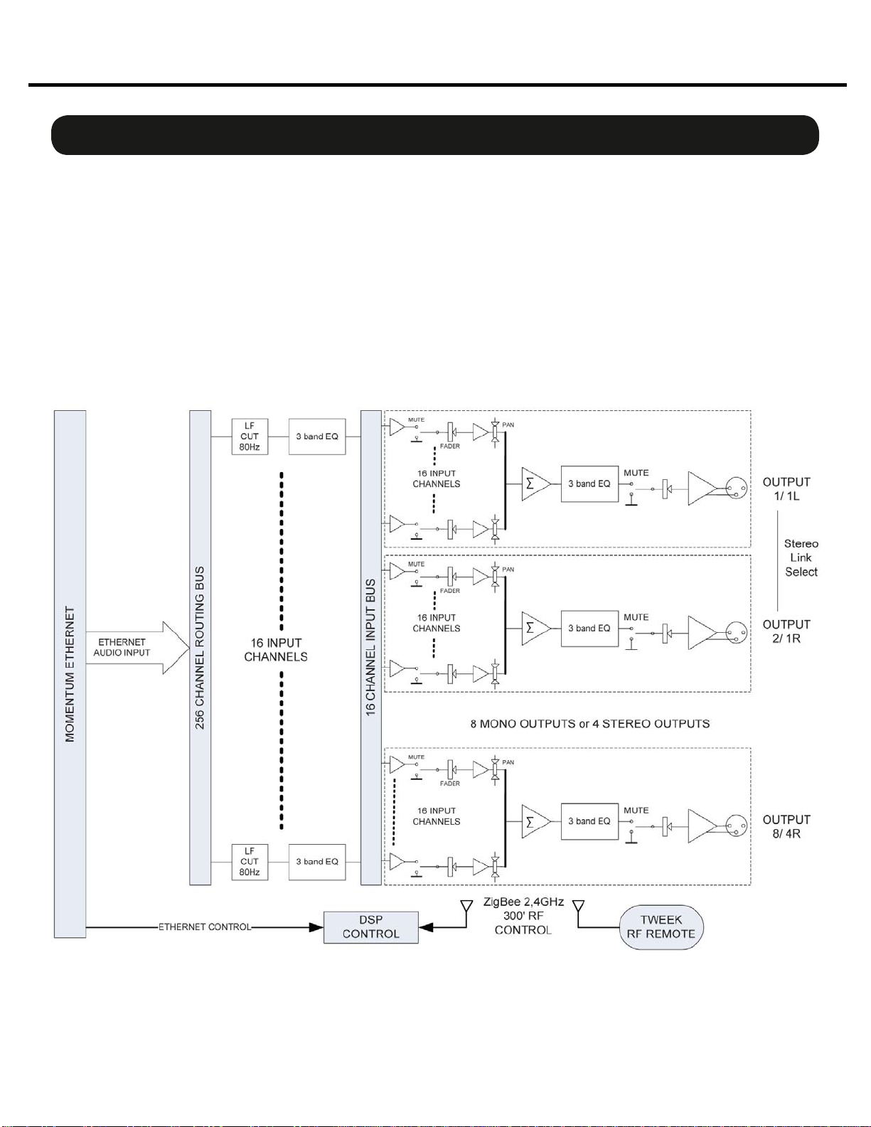
The Momentum mo8me is the DSP based mix engine component of Pro Co’s digital snake system. It utilizes 16
network inputs with 3 band EQ and HPF (high pass filter). Output mixes can be mono or stereo and include 3
band EQ and panning control. The mo8me is suitable for numerous tasks such as personal monitor mixing and
distributed audio systems.
Gigabit Ethernet is standard on all Momentum audio products and all components are Power Over Ethernet (PoE)
802.3af compliant. All DSP functions are controlled by the “Tweak”, a wireless user interface, or PC software. In
order for the mo8me to function as it has been designed to, a minimum of one or two input (mi8) devices must
be present on the Network. A full compliment of options are available to ensure that Momentum can integrate
into your system configuration.
Block Diagram:
8
Momentum mo8me Manual
6
1
2
34
7
The mo8me enclosure can be used in a number of different configurations depending on the needs
of the end user. Units are shipped with rack ears, which can be front or rear mounted or can rotate
for vertical or horizontal surface mounting. Optional rubber stage boots allow the units to be used as
stage boxes.
An optional contractor panel can be ordered, which then allows the end user to terminate all analog
connections with simple “phoenix” screw terminal connectors or utilize a standard DB25 “break out
cable” instead of the front panel XLR connectors. This also allows passive “splitting” of the analog
signals if needed. Pro Co offers whatever breakout cables you need. Just ask for them when you
order your system.
mo8me Front View with optional Stage Boots
mo8me Front View with Rack Ears
Overview
Chapter 1
The mo8me Enclosure
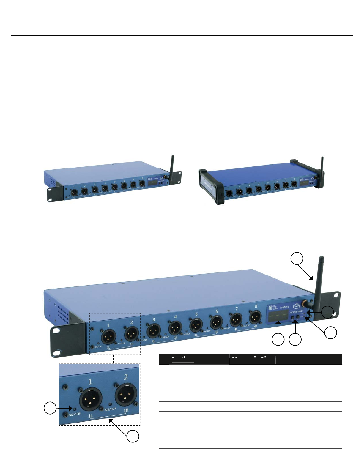
Front Panel
The front of the mo8me has a 2-button control panel, eight channels capable of any combination
of eight mono and four stereo output mixes and an antenna for remote mixing. Each channel has
one signal / clip LED indicator that is visible on the front panel.
The control panel includes a power LED, status LED,
a 3-digit readout display and control buttons.
Index
I
n
d
e
x
Description
D
e
s
c
r
i
p
t
i
o
n
1
S
i
g
nal/Clip LE
D
Green = -40dB F.S. or above;
Re
d
= -
3d
B F.S.
o
r
abo
ve
2
S
tere
o
Ch
a
nnel mo8me
o
ffers 4 stere
o
ch
a
nnel
s
3
D
is
pl
a
y
Th
ree c
h
aracter LCD
d
is
pl
a
y
4
F
1
&
F1 Select
o
r
s
S
elect
a
n
d
e
d
it mo8me f
u
ncti
o
ns
5
S
t
a
t
u
s LE
D
Green = Au
d
io s
y
nc
p
resent;
Red = Network faul
t
6
Po
wer LE
D
Green = Di
g
ital power OK
7
A
ntenn
a
C
o
mm
u
nic
a
tes with
m
r
c
5

9
Momentum mo8me Manual
Overview
Chapter 1
Rear Panel
The rear panel offers network status LEDs for monitoring the unit’s network connection. The
mo8me may be purchased with an optional contractor panel. Shown below.
LED
D
escr
ip
t
i
o
n
1
A
c
tiv
e
Link
S
hows network activit
y
2
TX
In
d
ic
a
tes t
ha
t t
h
em
o
8me
is
t
ransmittin
g
data on the network
3
1
000
mIn
d
ic
a
tes th
a
t the m
o
8me i
s
connected at one
g
i
g
abit
4
Qualit
y
Indicates an acce
p
table Ethernet
s
i
g
na
l
to noise rati
o
Rear View with Contractor Panel
The optional contractor panel allows input analog connection from the rear of the device. These
inputs are connected in parallel to the XLR connectors on the front of the mo8me.
2
4
3
1
MRC (The “Tweak”)
The “Tweak” is the companion mrc (Momentum remote control) unit to the mo8me. It is a wire-
less remote control that allows the user to create and save personal mixes. See chapter 5 for a
more detailed description of the Tweak’s functions.
1
2
Index Descr
ip
t
i
o
n
1
8 Soft Button
s
U
sed to select functions, E
Q
ba
n
d
s
a
n
d
s
a
ve
d
mixes.
2
Enc
od
er
T
urn to to
ggl
e c
h
anne
l
s an
d
pus
h
down to return to
p
revious screen

10
Momentum mo8me Manual
One Spot or MUPS power supply ports
Ethernet port
P
o
w
e
r
Only use with the power supplies provided by Pro Co Sound.
Use the1. Pro Co One Spot power supply. It is shipped with the unit and allows the powering
of only one device. An alternative to the One Spot is the Multi Unit Power Supply (MUPS).
This power supply comes with three jumper cables that will allow up to four units to be linked
together and powered by one MUPS. The MUPS is a separate option and must be ordered
additionally.
Use a standard2. Gigabit IEEE 802.3af PoE network switch and power up through the
Ethernet cable. The POE switch must be capable of 15Watts per Ethernet port.
The Momentum output unit requires 48VDC power to operate. There are two ways to power the unit:
Only use 802.3af PoE power supplies.
OR
Chapter 2
Connection and Startup 2

11
Momentum mo8me Manual
Pin T568B (female) Description
1 Orange/White
2 Orange
3 Green/White
4 Blue/Power
5 Blue/White
6 Green Receive
7 Brown/White
8 Brown Power
Bi-directional pair +A
Bi-directional pair - A
Bi-directional pair +B
Bi-directional pair +C
Bi-directional pair - C
Bi-directional pair - B
Bi-directional pair +D
Bi-directional pair - D
Copper Wiring
Use a minimum of• CAT5E or CAT6 network cable
Maximum cable length is 100 meters•
Connection and Setup
Chapter 2
N
etwor
k
Wi
r
i
n
g
Copper Connection
Use T568B or equivalent connectors when wiring your system. This view shows the color code as• viewed from the front of the female socket or the rear of the male connector.
Crossover wiring is not needed; the Momentum network interface compensates for unit-to-unit• connections.
Fiber Connection (Optional)
220 meter distance use 62.5/125um MMF 160MHz Km Cable
275 meter distance use 62.5/125um MMF 200MHz Km Cable
500 meter distance use 50/125um MMF 400MHz Km Cable
550 meter distance use 50/125um MMF 500MHz Km Cable
The Momentum Fiber option uses ST style connectors and operates at 850nm. The system is fully
IEEE 802.3z Gigabit Ethernet compliant. The following are performance based on the cable type:
T568B
12
Momentum mo8me Manual
Network
C
on
fi
g
urations
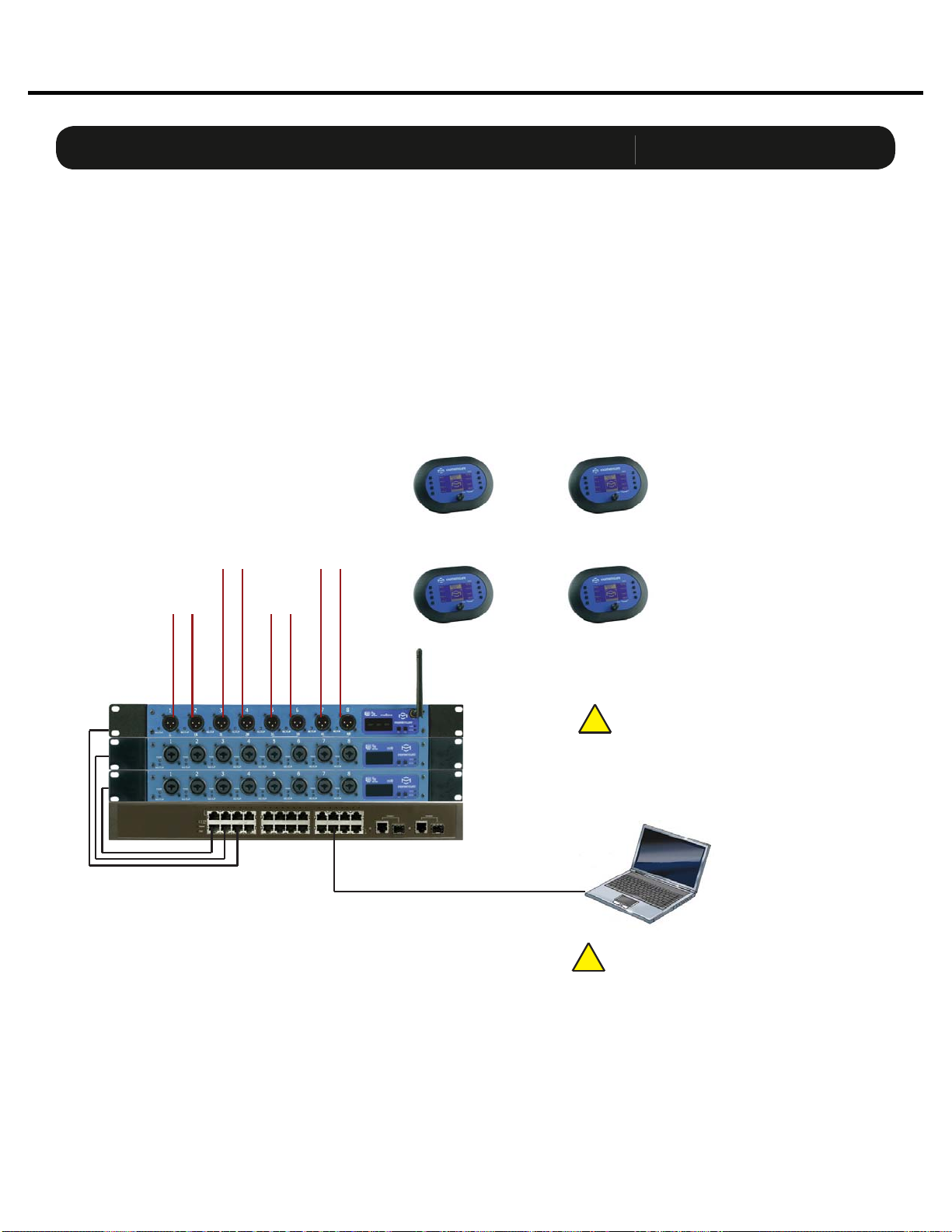
The following are examples of network configurations. These samples show configurations using ana-
log inputs and outputs. Momentum digital input and outputs or DSP devices use the same methods for
network configuration.
Using the Momentum system, the network configuration possibilities are endless. For more information
on advanced configurations and support, visit www.procomomentum.com. For further support, con-
tact you local dealer or Pro Co technical support.
Connection and Setup
Chapter 2
Basic Mix System
mo8me Mix Engine
Chn=001 Adr=003
mi8 Input
Chn=001 Adr=001
mi8 Input
Chn=009 Adr=002
CAT5E or CAT6
Ethernet Switch
Control Device
If running over 48 channels, you MUST
set the Ethernet port that is connected
to your control PC to multicast filtering.
Multicast MAC 01:15:AB:C6:00:00
(See Network Design White Papers)
!
Chn 001 must be present on the
network at all times. This unit will sync
the network clock.
!
To In-Ear
Monitors
Mix 1
To In-Ear
Monitors
Mix 2
To In-Ear
Monitors
Mix 3
To In-Ear
Monitors
Mix 4
Wireless
Mix 1 Control
Wireless
Mix 3 Control
Wireless
Mix 2 Control
Wireless
Mix 4 Control
SHOWN IN STEREO MODE

13
Momentum mo8me Manual
Connection and Setup
Chapter 2
S
etu
p
Network Clock Sync
PLEASE TAKE NOTE OF THE FOLLOWING:
The Momentum network MUST have ONE mi8 that is assigned CHANNEL 1. This assignment is
used to synchronize all of the device clocks on the network. Without this assignment, the system
clock will not sync and audio ‘clicks’ will be heard.
The mo8me unit includes a control panel with an LED display and two push buttons (F1 and
F2). The device can be configured through a series of key strokes using F1 and F2. The control
panel will only control the local device and cannot change other units via the network.
Using the Control Panel
F1 - Mode Edit / Decrease Value
F2 - Mode Select / Increase Value
Display
Status Indicator
Power Indicator
Button
/
LE
D
Descr
ip
t
i
o
n
F1 Mode
S
elect
:
F1 activates the edit mode within a
p
articular function.
F2 Mode Select
:
F2
g
enerally selects which function to edit.
P
o
w
e
r In
d
i
ca
t
o
r
:
T
he power indicator shows that a power source is connected to the
Momentum units. The LED is connected to the di
g
ital power source.
A
ll
ot
h
er
p
ower sources in t
h
e s
y
stem can
b
e monitore
d
via t
h
e PC
so
ftw
a
re.
S
t
a
t
us
In
d
i
ca
t
o
r
:
Th
e st
a
t
u
s in
d
ic
a
t
o
r is
a
b
i-c
olo
r LED.
G
REEN
i
n
d
ic
a
tes
all
M
o
men-
tum Network connections have been found and the network is run
-
nin
g
.
R
ED
i
ndicates there are one of two problems;
1
)
An Et
h
ernet
l
in
k
is not esta
bl
is
h
e
d
or is not connecte
d
.
2
)
The audio s
y
nc
p
acket
(
channel 1
)
is not found.
14
Momentum mo8me Manual
The mo8me does not require a start channel. The unit is shipped with routing channels pre-set to
Network input channels 1-16. This function can be used to change the factory default if required,
to another set of sixteen sequential channels.
The start channel, in this case, will be the first of the selected sixteen inputs. While in resting or
time-out mode, the mo8me will display “- - -” . Channels are set in grouping of sixteen i.e. 1-16,
17-32, 33-48 etc.
Start Channel Route
Connection and Setup
Chapter 2
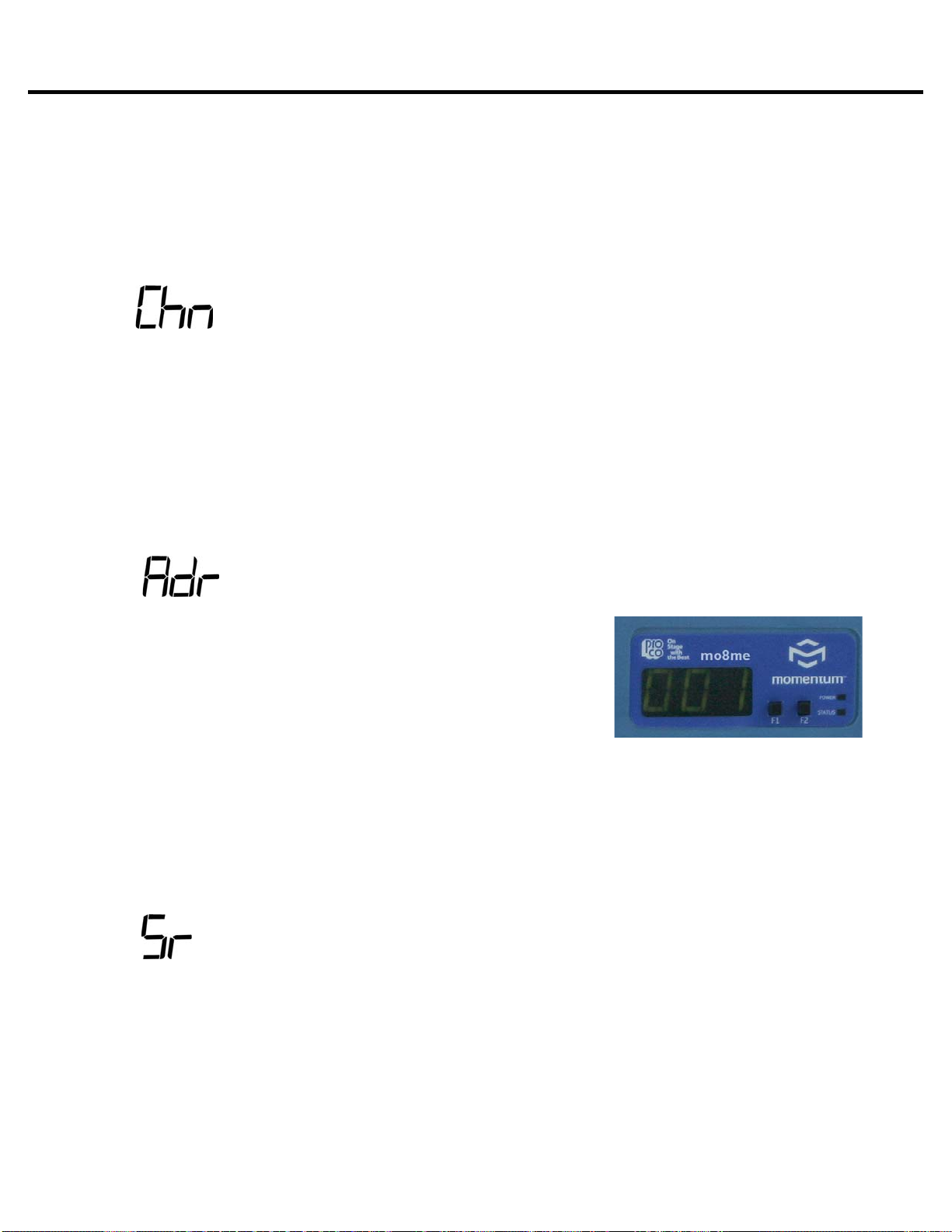
An IP address will need to be set only if the Momentum
network will be controlled with a PC or external controller.
The IP address defaults to 192.168.1.1. When in the idle
menu state, pressing the F1 button will flash the current ad-
dress. The number shown is the LSB of the IP address
(192.168.1.[LSB]). If the network is to be controlled with
a PC, each mi8 unit will need a unique IP address. All IPs
need to be set manually on the individual unit.
It is best practice to keep the input unit’s IP address sequential with its channel. In other words,
Chn 001-008 would be Adr 001 and Chn 009-016 would be Adr 002 and so on.
PLEASE NOTE: The mo8me can ONLY be set at a sample rate of 48k. All other network
devices must also be 48k. A setting for sample rate 96k has been added for future use, but it is
not available at this time.
IP Address
Sample Rate
THE FOLLOWING FRONT PANEL SETTINGS MUST BE CONFIGURED PRIOR TO USING MOMENTUM.
The IP setting is required only if the unit is to be controlled with a PC or external controller.
A detailed description of control functions can be found in chapter 3, pages 16-17.
Setting Device Before Use

15
Momentum mo8me Manual
This chapter describes each of the control panel functions and how to access them to make changes to
your network. Changes are made using the F1 and F2 keys.
Display
F2 - Function Select / Increase Value
The settings of the Momentum units are accessible through a series of key strokes between F1 and F2.
In general, F2 selects which function to edit, and F1 activates the edit mode within that function.
The flow chart below displays each of the controlling F1 and F2 functions. Descriptions of each functions
follow in a guide on pages 16 and 17.
F1 - Function Edit / Decrease Value
F1
a
n
d
F2 F
u
n
c
ti
o
n
s
Chapter 3
Control Panel Functions 3
F2
[rou]
Route
F2
[Chn]
Start
Channel
F2
[Adr]
IP
Address
F2
[Sr]
Sample
Rate
F2
[Clr]
Clear
Settings
F1
[Adr]
IP
Address
Display
F1 F2

16
Momentum mo8me Manual
Individual Channel Route
IP Address View
Control Panel Functions
Chapter 3
Description of Functions
Pressing F1 will flash the IP address of a unit.1.
Toggle F2 to until rou is displayed.1. Tap F1 to activate rou “edit” mode.2. Toggle F1 to scroll channels. Toggle F2 to select a channel.3. Tap F1 to decrease value. Tap F2 in increase value.4. Press and hold F1 and F2 to execute and save the change.5. Return to selecting channels or exit by allowing display to time out.6.
To return to the beginning of the menu, allow the display to time out. When the display times out and
when the unit is at idle, the LCD will display “ - - -”.
Please note:
The functions in the step by step guide are presented in the same order as the functions1. on the unit’s menu structure.
In order to edit a channel, the user must first scroll to the function in need of editing, select2. the appropriate channel and make the edit.
Channel Start Route (Off or 1-249)
Toggle F2 until Chn is displayed.1. Tap F1 to activate Chn “edit” mode.2. Tap F1 to decrease value. Press F2 in increase value. Channels increase/decrease in3. groupings of eight. (Off mutes all channels)
Press and hold F1 and F2 to execute and save the change.4.
The channel route function is used to route any 16 of the 256 Network input channels to
the mo8me.
The start channel routes sixteen channels in groupings of eight. The mo8me channels are
named sequentially ie. 1-16, 17-32, 33-48 etc.

17
Momentum mo8me Manual
Clear Settings
Sample Rate
Control Panel Functions
Chapter 3
Within this function, selecting Clr will allow the user to reset the IP to the factory default of1. 192.168.1.1.
Toggle F2 until Adr is displayed.2. Tap F1 to activate Adr “edit” mode.3. Tap F1 to decrease value. Press F2 in increase value. (Toggle F2 to select Clr to set the IP4. to factory default of 192.168.1.1.)
Press and hold F1 and F2 to execute and save the change.5. Exit by allowing display to time out.6.
The sample rate is currently only available in 48K. The sample rate on the mo8me is set to
default to 48K. Although 96K will be displayed as an option in the Sr function, the user will be
unable to execute and save this sample rate change.
This function can be used to reset all current mixes back to the factory default.1. (This WILL NOT effect saved mixes. Saved mixes can only be cleared via a PC)
Toggle F2 to select Clr.2. Tap F1 to activate Clr. (It will flash)3. Press and hold F1 and F2 simultaneously to execute and save the change.4. Exit by allowing display to time out.5.
Description of Functions
IP Address Edit
18
Momentum mo8me Manual
4
O
verview
The following chapter will outline the Tweak’s features and give detailed descriptions of its functions.
The Tweak is the companion remote unit to the mo8me and offers the user flexibility in remotely mix-
ing input channels from the Momentum Network. It is suitable for such tasks such as personal monitor
mixing and distributed audio systems.
Features of the Tweak
The Tweak’s factory default• mo8me address is set to Network channel 1.
All users share EQ, routing and channel names.• Up in eight Tweaks can mix from one• mo8me.
Each Tweak in a given environment must have a unique Tweak ID 1-99.• Time-out mode can be turned off or be setup for up to 4 minutes.• If unit times out, it will resume to last screen in use when reactivated by pressing any button• FCC approved.• Operating frequency - ISM 2.4GHz.• Wireless range - 300’ indoors.• Approved for use in US, Canada, Australia and Europe.•
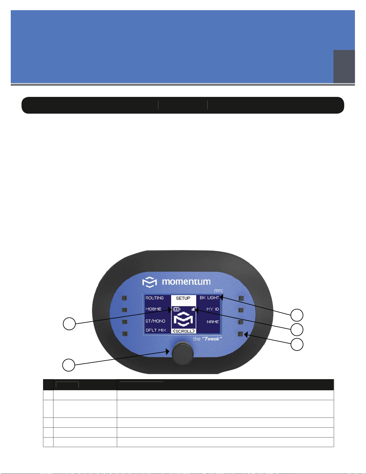
Index Descr
ip
t
i
on
1
B
atter
y
Indicato
r
Indicates level of batter
y
p
owe
r
2
E
nc
od
e
r
1) Turn to scroll between menu screens, channels and to ad
j
ust mixin
g
l
evels 2
)
Push down to return to
p
revious scree
n
3
Soft Button
(
8
)
S
elects functions and menu items based on the dis
p
la
y
4
S
i
g
nal Indicato
r
Indicates the stren
g
th of the remote si
g
nal
5
Na
me
o
f F
u
ncti
on
Displays function
s
5
4
3
1
2
Chapter 4
The Tweak: Overview and Setup

19
Momentum mo8me Manual
Opening Screen
S
creen Ite
m
D
escr
i
pt
i
o
n
C
onnectin
g
to Addr: X
D
is
p
la
y
s the mo8me
add
ress t
o
which the Twe
a
k is c
o
nnecti
on
S
tatus: Failed
T
his indicates one of two thin
g
s:
1. Th
e
mo
8
me is not powered up
2. T
h
e connectin
g
m
o
8me
add
ress is inc
o
rrec
t
(
See the New Unit screen to reset the m
o
8me address, pa
g
e 22
)
P
ress an
y
ke
y
to continue
P
ressin
g
any key will take unit to the Communication Time Out
s
creen (See pa
g
e 20)
P
ower
i
n
g
U
p
The Tweak: Overview and Setup
Chapter4
First Power Up
The Tweak is powered by 3 AAA batteries inserted at the back of the unit.• Push down and turn the back panel to remove it.• The Tweak will power up when batteries are inserted.• The unit will default to a Network address of 1.• When not in use, the unit automatically times out.• Press any button to resume.• It will resume to the last screen in use before time out.•
After powering up for the first time, please take the following steps:
(If these steps are missed, the Tweak will be unable to set routing or any of the other
mixing capabilities.)
The unit is shipped with a factory default Network address of 1, which may not correspond• with your mo8me address, especially if you already have a Network up and running. You
MUST reset the Tweak to the correct Network address. (See page 20 or 22)
Assign your Tweak a unique ID number. (See page 24 - Assigning Your Tweak an ID Number)•
Note: After initial power up, and if the Tweak has been reset to the correct address, the Opening
and Communication Time Out Screens will automatically be skipped during the next power up. The
Tweak will then open to the last screen in use.

20
Momentum mo8me Manual
The Tweak: Overview and Setup
Chapter 4
Main Menu Screens
Set Up Menu
Mix Menu
All Setup screen functions are illustrated and detailed in this chapter. (See page 21)
All Mix capabilities are illustrated and detailed in Chapter 5. (See page 26)
Communication Time Out Screen
So
ft Butt
on
Descr
i
pt
i
o
n
R
F
O
f
f
T
he Tweak will not tr
y
to reestablish connection until
p
ower c
y
cle or
m
o
8me a
dd
ress is c
h
an
g
e
d
Goto Setup
T
akes user to New Unit screen to view and chan
g
e current address (See
pa
g
e
22
- Connectin
g
to a m
o
8me Unit
)
A
bo
rt
T
erminates communication attempt
R
etr
y
R
etr
i
es commun
i
cat
i
o
n
The Tweak will go to the Communication Time Out Screen if the mo8me is not powered up
or if the address is incorrect. This screen could also appear if a communications error occurs while
Tweak is in use (i.e. User steps outside of the wireless range). If the Network is up and the address
is correct, this screen will be skipped.
Other manuals for Momentum MO8ME
1
Table of contents


