pro-drive shallow water outboard User manual

1
OWNERS MANUAL
www.prodriveoutboards.com
PO Box 949
129 S Main St.
Loreauville, LA
70552
PH#: 337-
229-0034
FAX#: 337-
229-2302

2
Table of Contents
Desc. Page
•Safety Instructions 3
•Installation Instructions 4
•Unit Component Identification 5
•Identifying The Controls 6
•Start Up 7
•Operation Instructions 8,9
•Reverse Procedure 10,11,12,13
•Unit Maintenance 14,15,16,17,18
•Prop Removal and Installation Instructions 19,20,21
•Trouble Shooting Tips 22
•Warranty Information 23,24
TO THE OWNER
Thank you for purchasing a “Pro-Drive Shallow Water Outboard”.
Your unit is designed for long life,dependability, ease of operation,
safety, and top performance that you deserve and expect.
Take time now to read this manual and the safety precautions.
Everyone who operates this unit must read and understand this manual.
The time you take now will prolong your units life and prepare you for
its safe operation.
Thanks again and enjoy.

3
Safety Instructions
•Read and understand engine manufacturer’s owners manual.
•Attach safety kill switch lanyard to you before starting the engine.
(Attaching the safety kill switch is a suggestion only. Know your risks and
situation before electing to use or not to use.)
•Do not engage clutch while running engine out of water. Personal injury
can occur if prop is spinning in open air.
•Keep legs and body clear from under tiller handle.
•Engage clutch to forward at idle only.
•Always disconnect the battery before servicing the engine.
•Never touch or attempt to remove the propeller, until the battery is
disconnected.
•Remember to follow all boating regulations and wear your personal
flotation device while on the water.
•Never use this unit when under the influence of alcohol or any other
drug.
IMPORTANT
Read and understand these instructions. They are for your safety. Failure
to follow these instructions may result in porperty damage, personal
injury, or death.
4
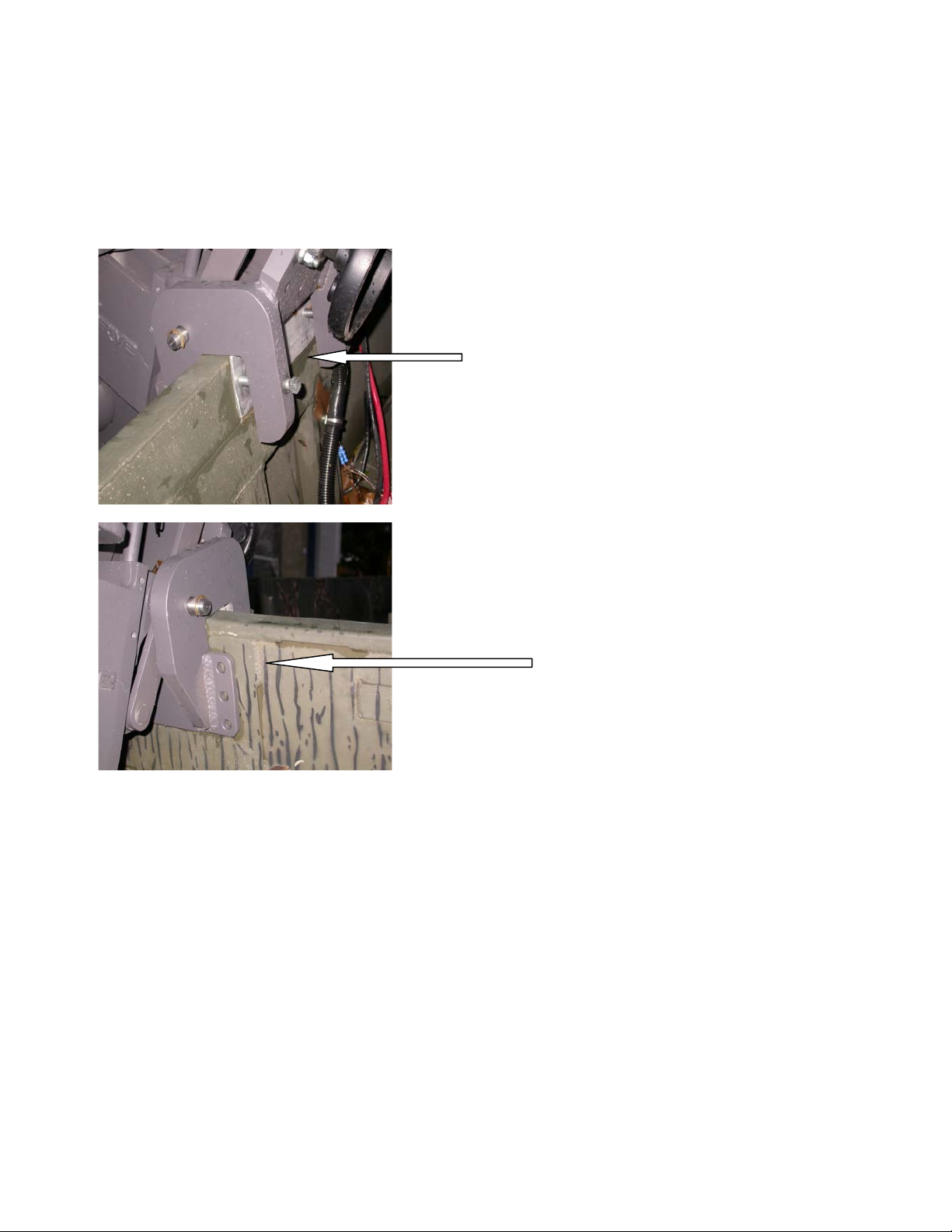
Installation Instructions
After installing your motor on the boat transom
use the aluminum transom saver plate supplied
with the unit, torque the boats to 25 ft. Lbs. Of
torque.
Located on the back of the transom bracket there
are three sets of holes on each side. Drill a 7/16”
hole through the transom. One on each side in the
hole most suited for your boat. Use the 3/8” bolts
and nuts supplied with your unit to secure the
bracket in the holes drilled.
*Note: Use ¼” fuel line and fittings with hose clamps to connect your engine fuel line to
your tank.

5
Unit Component And Control Feature Identification
Engine
Control
Box
Twist Grip
Throttle
Trim Wheel
Friction Screw
Tilt
Handle
Lower Unit
Tower
Housing
Prop
Tiller Handle
Trim Wheel
Skeg Plate
Cavitation
Plate
Transom
Bracket
Your PD# Is
Located Here
6
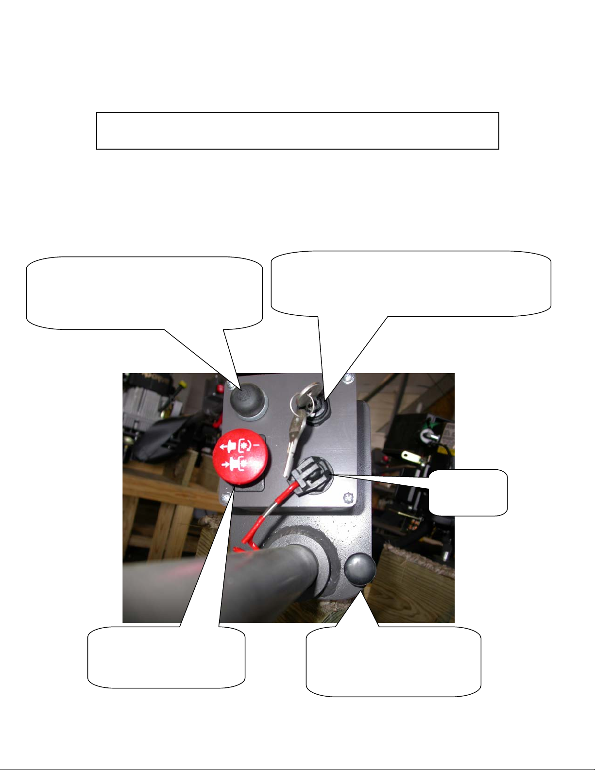
Identifing The Controls And Control Box
Safety
Kill
Momentary Engagement Button
Push In (Forward)
Release (Neutral)
Iginition Switch
(Off / Clockwise On)
Continue Clockwise Engages Starter
Choke Switch
Pull Out (Engaged)
Push In (Disengage)
Clutch Switch
Push In (Neutral)
Pull Out (Forward)

7
•Visually check unit for any loose, damaged or missing parts.
•Attach safety lanyard if electing to do so.
•Check engine according to the engine owners / operators manual.
•Make sure clutch is depressed (neutral position). *note engine will not start if
clutch is engaged.
•Pull out choke and turn ignition key clockwise to the start position.
•Once engine has started push the choke back in and allow engine to warm
up.
•After warm up, engage the clutch and accelerate by using the twist grip
throttle on the tiller handle and your on your way.
•Remember only engage the clutch at idle. You may disengage the clutch at
any time. Engaging the clutch at high rpm against a log or blunt object can
damage the clutch and void the clutch warranty.
•Momentary clutch engagement (forward) may be used by depressing the
black button while the clutch button (red button) is pushed in (disengaged)
START UP
*Note: your engine is shipped without oil. Oil
must be added before starting your engine. See
the engine manual. (Check before adding oil. Do
not overfill)

8
Regular Operation
•Make sure engine ignition is off.
•Check engine oil.
•Attach safety kill switch. (If electing to do so.)
•Make sure clutch button is pushed in ensuring it is in neutral. (Note: Engine
will not start while the clutch button is pulled out.)
•Pull choke as needed and start engine. Allow engine to warm up.
•Set trim wheel allowing the engine to be slightly above level with the boat.
•Pull out the red button to engage the clutch to go forward.
Note: only engage the clutch button while the engine is at idle. Engaging the
clutch at high rpm’s can damage the clutch and void the clutch warranty.
•While on step, adjust trim wheel at best performance for your boat. Once
your trim is set, there is no need to adjust it at any time, even while starting
and stopping in normal running conditions. Note: Do not try and submerge
your prop or cavitation plate while on step. Doing so will decrease
performance. Your prop is designed to run at the surface. (half of the prop is
out of the water while on step)
Footnotes: a) Tiller handle torque and slow speed indicates that the trim is set
too far down.
b) Extremely light tiller handle torque and speed loss indicates that
the trim is too high up.
Operation Instructions

9
Running In Grass, Hydrilla & Lillies With Water Underneath.
•While your boat is on step and running, no trim wheel adjustment is needed.
•Under extremely heavy conditions, you may need to trim down slightly, and
clear the prop by rasing the engine while getting on step. (Clearing the prop
may need to be done more than once in heavy vegetation while getting on
step.) Once on step, trim to normal running position.
Footnote: Raising the engine is done by pushing down on the tiller handle. If
needed, the tilt handle can also be pulled on simultaneously.
Running In Shallow Water To No Water On Soft Mud.
•While your boat is on step and running no trim wheel adjustment is needed.
•To take off from a dry stop in these conditions, you will need to trim your
motor down to near maximum depth.
•Engage the clutch and open the throttle fully.
•Using your tiller handle, work the engine from left to right pushing mud
until your boat is moving at about walking speed.
•Once you are at walking speed, trim up as you would under normal
conditions.
•You will now be able to slow your throttle down to your desired speed.
Footnote: Should your engine load up (lose power) while trimmed down in the
Above conditions, trim up using the hand wheel until the engine is
running normally again.
Reverse Operating Procedure

10
The concept is explained by comparing it to the same way a common ratchet and
socket set in your tool set works.
Below are some diagrams with explanations on how this system works.
First, you will have to adjust your friction knob by tightening it. This just like when
tightening a nut and bolt with a ratchet, some friction is needed to make the ratchet
mechanism work,
Step 1. While sitting, push your tiller handle with your right hand away from your
seated position. This will position your unit for reverse and allow you to access the
release pin.

11
Step 2. Pull the reverse release pin down. Pull the tiller toward you slightly, then
release the pin and continue pulling the tiller toward you until you here the unit
click. (Once you release the pin you will not have to pull the pin again until you are
ready to go back into the forward position.) Push the tiller handle away from you
again like in step 1 and repeat. When your reverse clicks for the fourth time your
pin will locate in the reversed locked position.
.
The pictures below show the unit rotating to reverse
12
This picture shows the release lever lock for units with hydraulic power trim in
the unlock position.
Step 3. Once the unit is in reverse, lock the trim down with the lever loc.
*Note: the reverse lever must not be locked when running in forward gear.
Repeat the above procedure to return to forward gear.
13
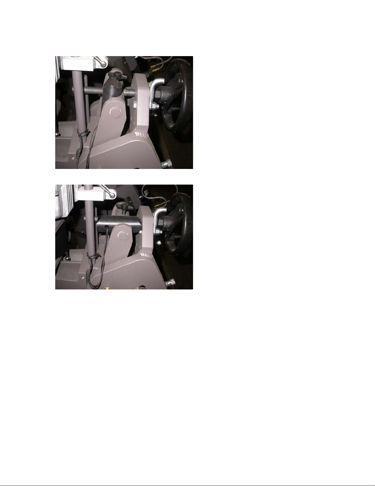
Manual Reverse Locking Block
This picture shows the reverse locking
block for a manual trim unit, in the
unlock position.
This picture shows the reverse locking
block in the lock position.
Important
While in reverse in deep water, (anything over 10 inches),
reverse gear should only be used at idle speeds. Full throttle
in deep water conditions could cause your boat to become
swamped.

14
Unit Maintenance
•Lower unit oil should be checked every 25 hours or once a month. Use only
SAE 80W-90 gear lubricant API service GL-5 (A synthetic gear oil such as
Royal Purple may be used.)
•Lower unit oil should be replaced once a year or every 50 hours. (See
diagram #B)
Diagram A – Checking the Oil
(Every 25 Hours or once a month)
Step #1
Remove the top outer plug with 1/4” allen wrench. Oil should flow
out or you should be able to see it. Top off if needed
Replace the plug using teflon tape. Do not over tighten.
15
Important
Added maintance procedure for 2008 model lower units
Your unit is already serviced new. This is for after 25 hours.
Long Shank Short Shank
Important
Pump only two shots of multi -purpose grease in the grease fitting every 25 hours of use or
once a year, whatever comes first. Replace the pipe plug.
Remove pipe plug
using 3/8” allen
wrench
Remove pipe plug
using 3/8” allen
wrench
With mo tor turn ed
completely straight
locate grease fitting.
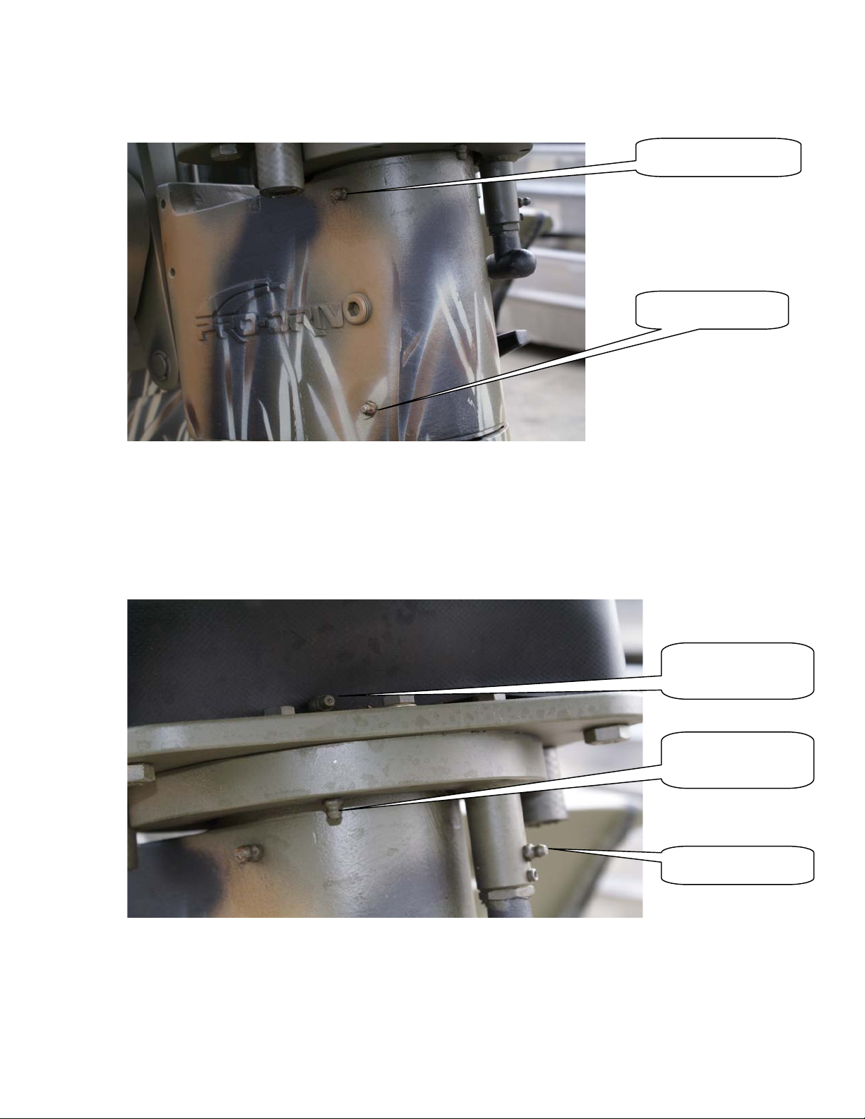
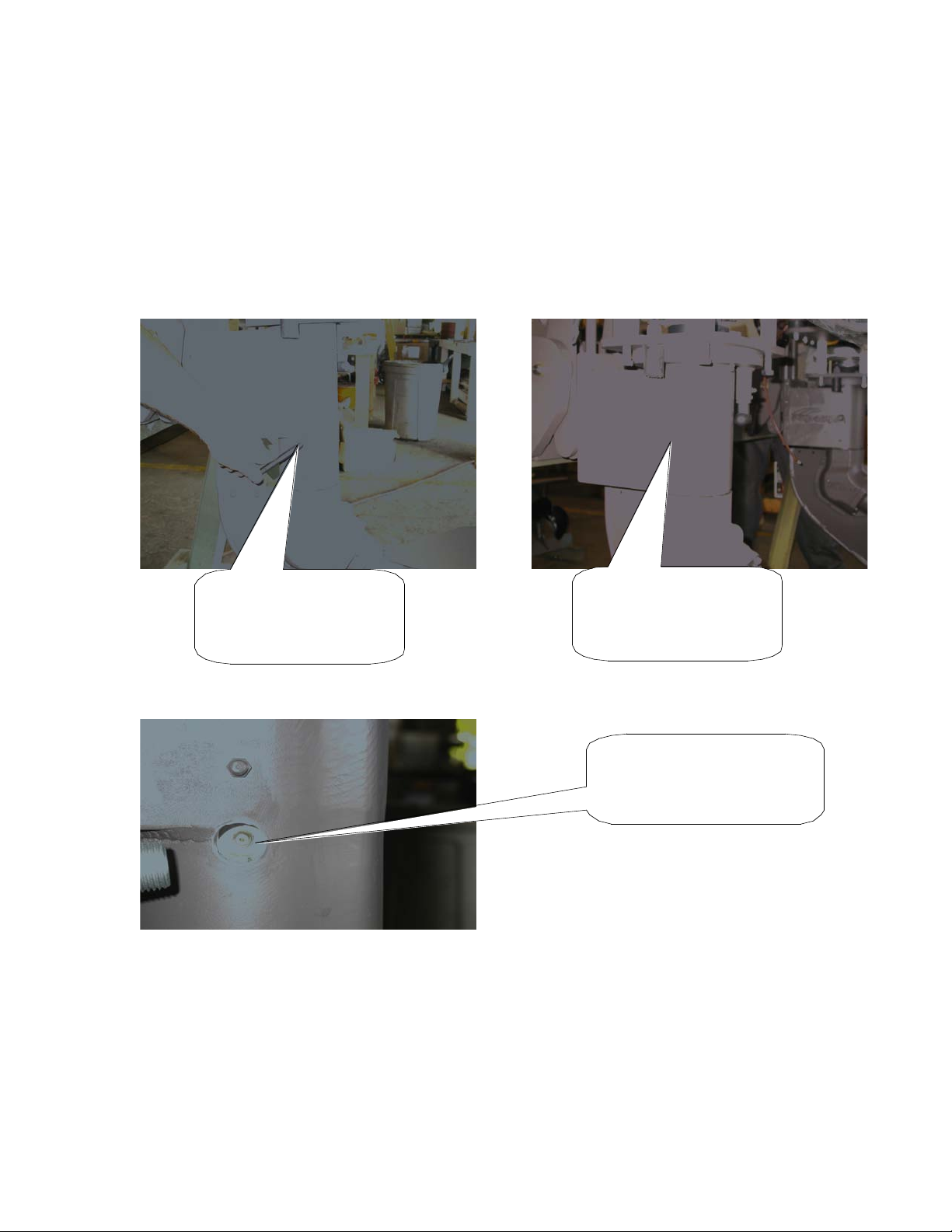
16
The diagram below shows the tower housing sleeve grease fittings.
Pump two to three shots of grease here at 25 hours.
The diagram below shows the grease ports of the reverse assembly.
These needs to be greased every 25 hours or once a year. Pump two
shots of grease into each. Reverse should be rotated and two shots
of grease applied to grease port 1 and 2 every click of the reverse
until the unit has been rotated a complete 360 degrees.
GREASE PORT
GREASE PORT
Grease Port 2
Grease Port 1
Grease Port
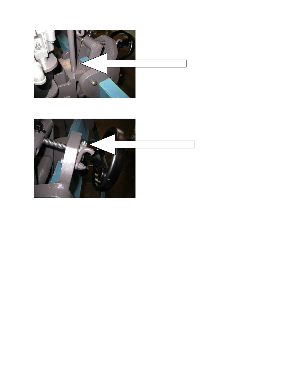
17
Grease tower housing pivot pin every 25
hours or once a season (located behind the
trim wheel)
Grease thrust bearing on trim wheel once a
year.
Salt Water Applications
•After returning from trip wash complete unit with fresh water and allow to dry.
Run engine.
•After engine cools. Spray engine and all components with Corrosion “X” or
equivalent. Spray muffler with WD-40
Remote Steering Rigs
•Check all choke cables, steering cables, and throttle cables and lube after each
trip.
*Note: Throttle rod inner bushing need to be lubed with silicon water based
Lubricate only. Any oil or petroleum based products will ruin the bushing.

18
DIAGRAM B – REPLACING OIL (Once a Year or every 50 hours)
*NOTE: IF YOUR OIL IS CLEAR AND NOT CONTAMINATED AT THE
INSPECTION OR DRAIN PORT, OIL DOES NOT NEED TO BE CHANGED.
STEP #1 REMOVE BOTTOM PLUG USING A 1/4” ALLEN WRENCH.
REMOVE TOP PLUGS AS INDICATED IN DIAGRAM A. THE OIL WILL
BEGIN TO DRAIN OUT OF THE BOTTOM PLUG.
STEP #2 ONCE OIL IS FULLY DRAINED, START FILLING FROM THE
BOTTOM PLUG . CONTINUE FILLING UNTIL OIL IS FLOWING OUT
OF THE TOP PLUG.
STEP #3 REPLACE THE BOTTOM PLUG USING TEFLON TAPE AND
FINISH BY REPLACING THE TOP PLUG WITH TEFLON TAPE AS
INDICATED IN DIAGRAM A.
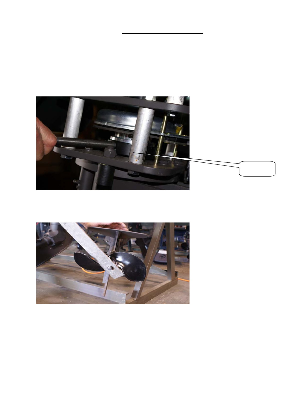
19
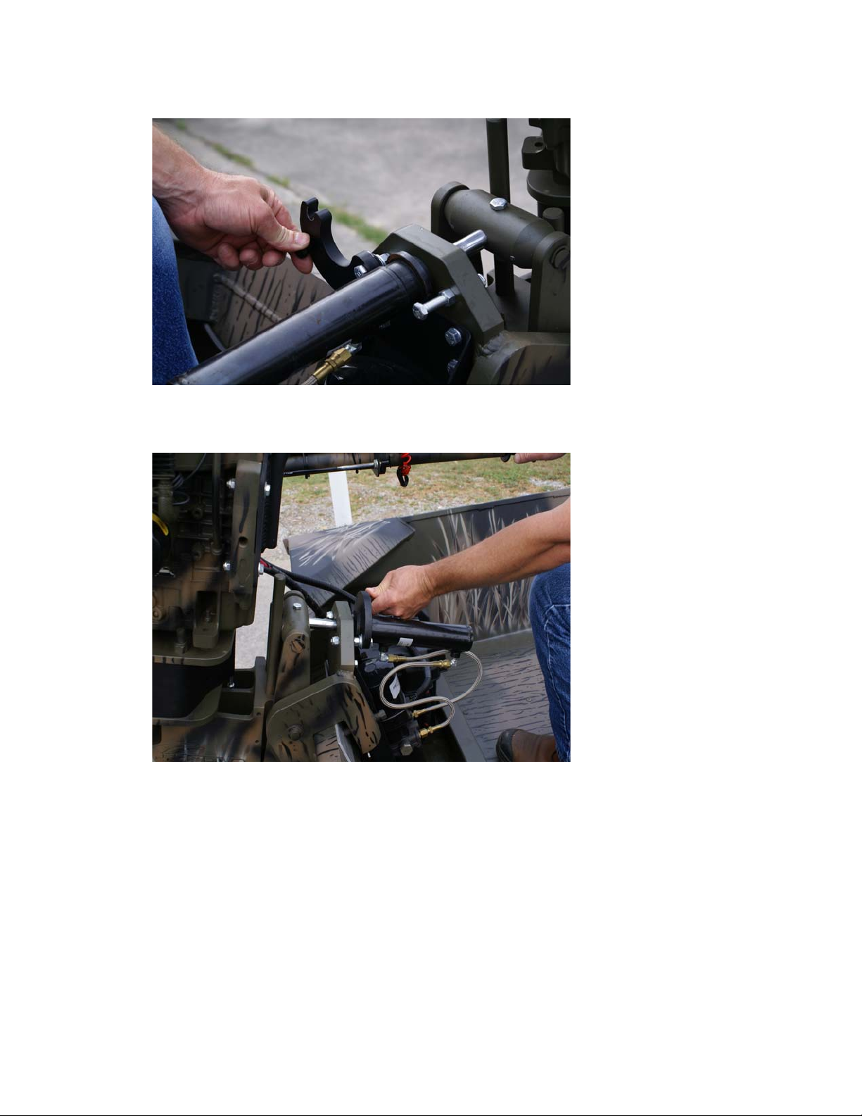
Propeller Removal
*Note: Do not engage the clutch to remove the prop. Doing so may damage
the clutch and void clutch warranty.
Always disconnect to battery before attempting to remove the
Propeller or any other work or service on your unit.
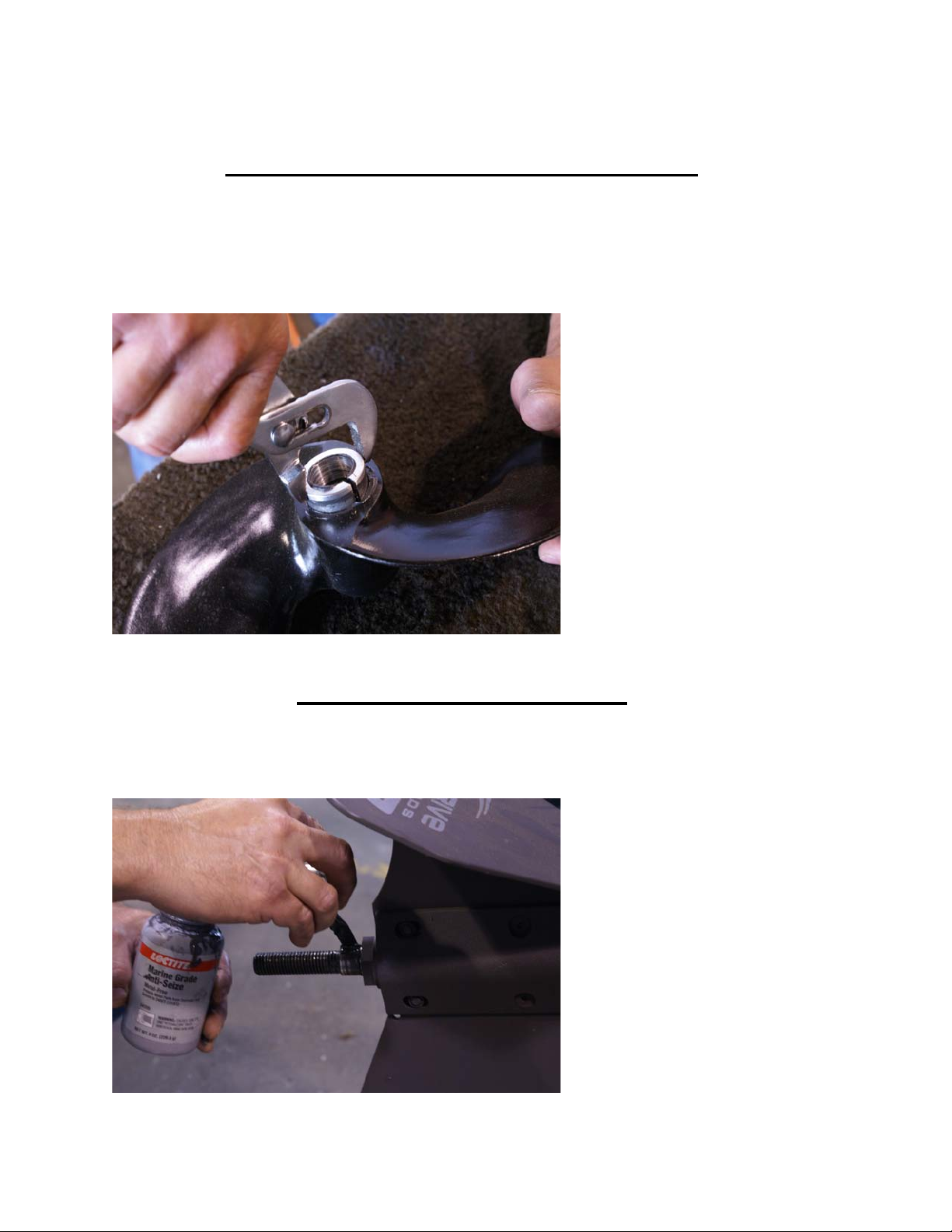
Remove the clutch cover wrap and locate the hole stop as shown on left. Insert ½” bolt
or prop pin into the hole stop. (the pin will push up against the plate post as back up
while unscrewing the prop.) *note: the prop unscrews to the left.
Remove prop nut using a 1-1/16” wrench or deep wall socket. Next, install the prop
wrench as shown . Replace nut to ensure that the prop wrench will not slip off when
removing prop. Turn the wrench counter clockwise until the prop is removed.
Hole Stop
20
Removing The Prop Taper Bushing
In most cases when the prop is removed the taper bushing will remain in the prop. To
remove the bushing use vise grip pliers or channel locks as shown below to compress
the bushing and twist slightly
Propeller Re-Installation
Using locktite marine grade ant-seize or never seize coat the entire shaft.
Table of contents
Other pro-drive Outboard Motor manuals

Popular Outboard Motor manuals by other brands


Vetus
Vetus BOW55HMD Installation and user manual

SLEIPNER MOTOR AS
SLEIPNER MOTOR AS SEP-IP100 installation guide

SLEIPNER MOTOR AS
SLEIPNER MOTOR AS SIDE-POWER SE IP 60/185 S installation manual

SLEIPNER MOTOR AS
SLEIPNER MOTOR AS SIDE-POWER SEP IP - 170 instruction manual

Outboard Marine
Outboard Marine T. EATON VIKING 22DE15V owner's guide

Yamaha
Yamaha F8C owner's manual


