Pro-face PFXZCGEUUE1 User manual
1
EZ LAN Adapter
Installation Guide
This product is a conversion adapter that
attaches to the USB (Type A) interface on the
display unit so you can use it as an Ethernet
interface. This product supports GP 4000 Series
and GP4000R Series (both are UL-certified).
Safety Precautions
If the equipment is used in a manner not
specified by the manufacturer, the protection
provided by the equipment may be impaired.
NOTE: When disposing of this product, follow
your country's regulations for similar types of
industrial waste.
Package Contents
(1) EZ LAN Adapter (PFXZCGEUUE1) x 1
(2) Attachment screws (M3) x 2
(3) Installation guide (this document)
This product has been carefully packed with
special attention to quality. However, should you
find anything damaged or missing, please
contact your local distributor.
DANGER
POTENTIAL FOR EXPLOSION
• Suitable for use in Class I, Division 2,
Groups A, B, C, D or non-hazardous
locations only.
• Substitution of any components may impair
suitability for Class I, Division 2.
• Do not connect or disconnect this product
unless power has been switched off or the
area is known to be non-hazardous.
Failure to follow these instructions will result
in death or serious injury.
DANGER
HAZARD OF ELECTRIC SHOCK OR
EXPLOSION
• Do not disassemble or remodel this product
in any way. Doing so may cause an electric
shock or fire.
• Do not use this product in areas where
flammable gases are present. Doing so may
cause an explosion.
• Do not allow water to enter the connector. Do
not touch the connector with wet hands.
Doing so may cause an electric shock.
Failure to follow these instructions will result
in death or serious injury.
WARNING
UNINTENDED EQUIPMENT OPERATION OR
LOSS OF CONTROL
• Do not use or store this product at
temperatures outside the range specified in
this guide.
• Do not use or store this product in direct
sunlight or excessively dusty or dirty
environments.
• Do not use or store this product in an
environment where it may be exposed to
chemical vapors or fumes.
Failure to follow these instructions can result
in death, serious injury, or equipment damage.
NOTICE
LOSS OF COMMUNICATION
Do not connect or disconnect this product during
communication. Doing so may cause a communi-
cation error.
Failure to follow these instructions can result
in equipment damage.
The information in this document is subject to change without notice.
Copyright © 2017.6 Digital Electronics Corporation. All Rights Reserved.
QGH29096 02 Printed in
Digital Electronics Corporation
Schneider Electric Osaka Building,
4-4-9 Kitahama,Chuo-ku, Osaka 541-0041 JAPAN
http://www.pro-face.com/

2
General Specifications
General Specifications
Electrical Specifications
Environmental Specifications
External Specifications
NOTE:
• Extending the length of the USB cable can degrade (weaken) signals, causing the potential for
errors. Do not extend the cable.
• Use only the SELV (Safety Extra-Low Voltage) circuit to connect the USB and Ethernet interface.
Connector type Ethernet I/F Modular jack (RJ-45), IEEE802.3i/IEEE802.3u,
10BASE-T/100BASE-TX
USB I/F Type A (plug), USB 2.0 High-Speed (480 Mbps)
Power
supply
Rated input voltage 5 Vdc (powered from USB bus)
Input voltage limits 4.75...5.25 Vdc
Power consumption 0.63 W or less
Physical environment
Ambient air operating
temperature 0...55 °C (32...131 °F)
Storage temperature -20...60 °C (-4...140 °F)
Ambient air and storage
humidity
10...90% RH (non condensing, wet bulb temperature 39 °C
[102.2 °F] or less)
Dust 0.1 mg/m3(10-7 oz/ft3) or less (non-conductive levels)
Pollution degree For use in Pollution Degree 2 environment
Atmospheric pressure
(Operating altitude) 800...1,114 hPa (2,000 m [6,561 ft] or lower)
Mechanical
environment
Vibration resistance
IEC/EN 61131-2 compliant
5...9 Hz Single amplitude 3.5 mm (0.14 in)
9...150 Hz Fixed acceleration: 9.8 m/s2
X, Y, Z directions for 10 cycles (approximately 100 minutes)
Concussion resistance IEC/EN 61131-2 compliant
(147 m/s2, X, Y, Z directions for 3 times)
Electrical
environment
Electrical fast transient/burst
IEC 61000-4-4
2 kV: Power port (display unit)
1 kV: Signal ports
Electrostatic discharge immunity
Contact Discharge Method: 6 kV
Air Discharge Method: 8 kV
(IEC/EN61000-4-2 Level 3)
External dimensions (W x H x D) 105 x 40 x 27 mm (4.13 x 1.57 x 1.06 in)
Cable length 0.5 m (1.64 ft) (including connections)
Weight 100 g (0.22 lb) or less
3
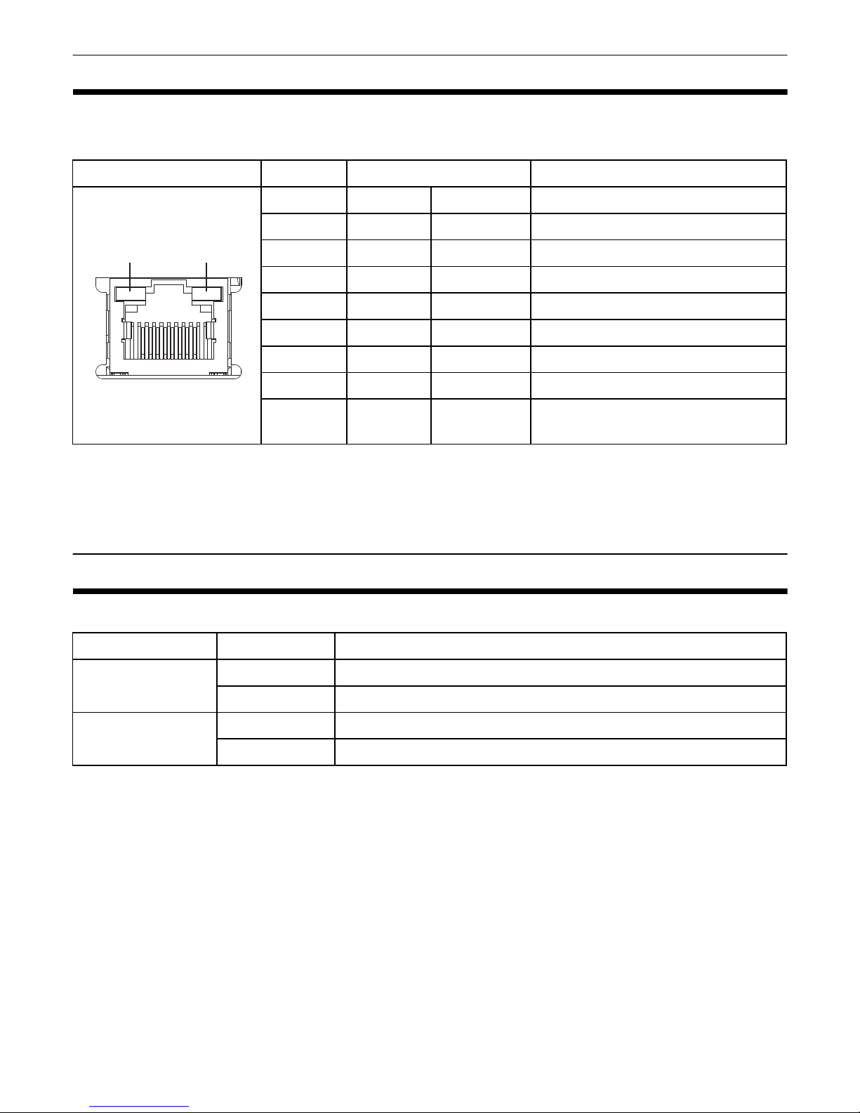
Interface
Ethernet Interface
NOTE:
• The SG (signal ground) and FG (functional ground) terminals are connected internally in this
product.
• Use an STP Ethernet cable and appropriately handle the shield wire.
Status LED
For the location of LEDs, refer to the figure in the "Interface" section.
Pin Arrangement Pin # Signal Name Meaning
1 TX+ Output Send Data (+)
2 TX- Output Send Data (-)
3 RX+ Input Receive Data (+)
4 NC - No connection
5 NC - No connection
6 RX- Input Receive Data (-)
7 NC - No connection
8 NC - No connection
Shell FG - Functional Ground (common with
SG)
Color Indicator Description
Green (Active) Flashing Data transmission is occurring.
OFF No data transmission
Green (Link) ON Data transmission is available in 10BASE-T/100BASE-TX.
OFF No connection or error
LinkActive
18
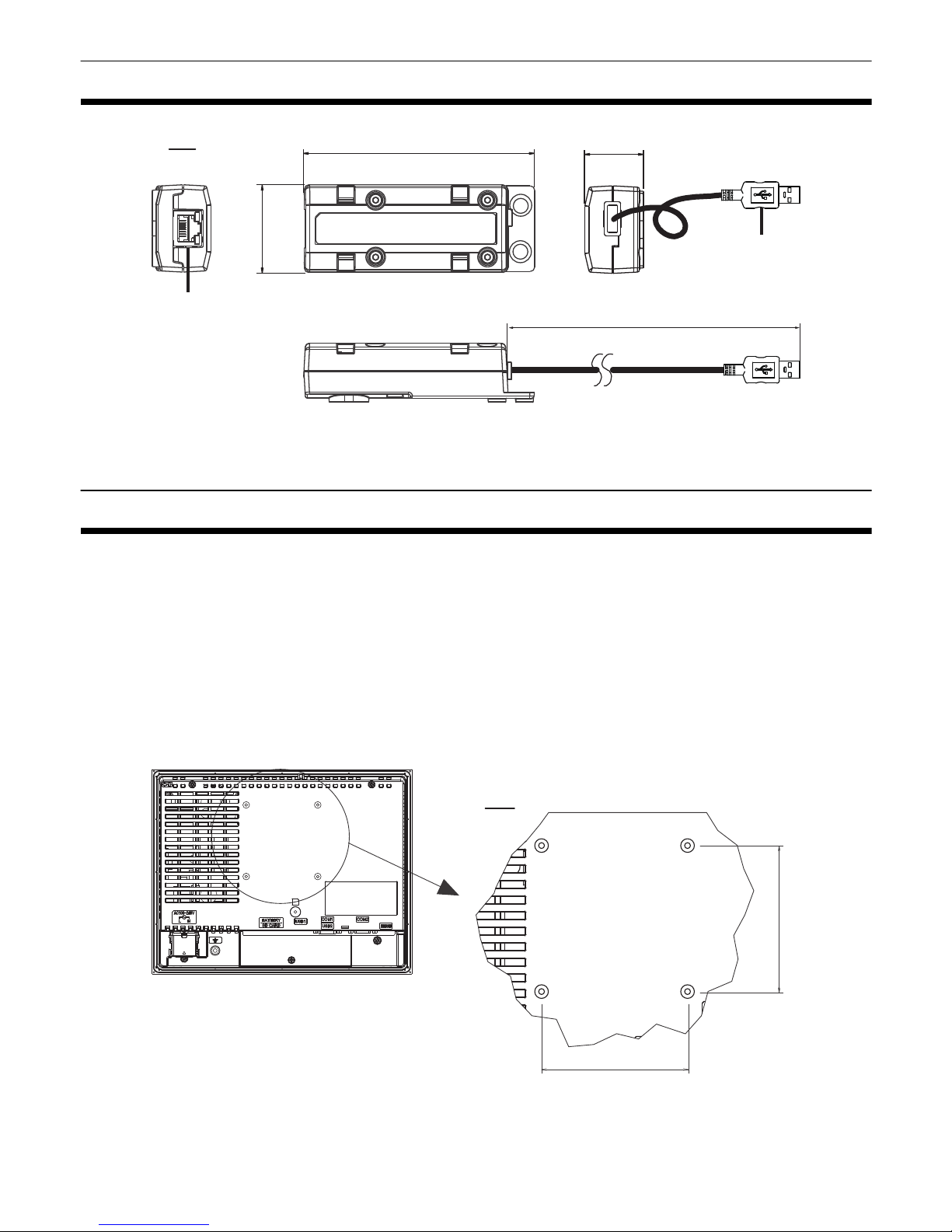
4
Dimensions
1 Ethernet Interface (Device/PLC side)
2 USB Connector (display unit side)
Attachment Method
NOTE: Attach this product to the panel when the display unit does not have screw holes on its rear
side as shown in the image below.
Attaching directly to the Display Unit
When attaching this product on the rear side of the display unit, among the 4 screws shown in the
diagram below, use 2 horizontally positioned or 2 vertically positioned screws to attach this product.
If the display unit already has an attachment, it may restrict the direction in which you can place this
product.
105
4.13
mm
in 27
1.06
500
19.68
40
1.57
1
2
75
2.95
75
2.95
mm
in
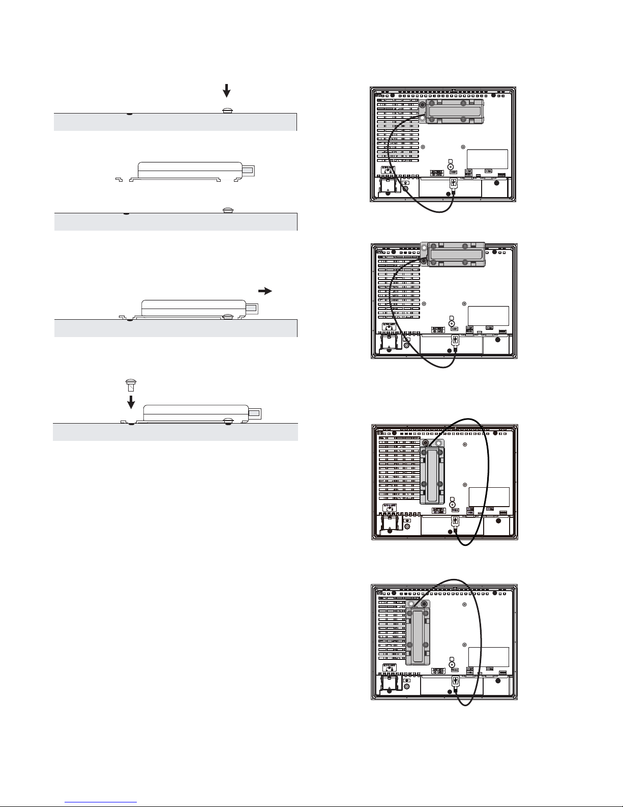
5
1) Using a Phillips screwdriver, attach one screw
(M3) to the display unit’s rear side. Use a torque
of 0.5 N•m (4.4 lb-in).
2) Attach this product to the display unit.
3) Slide this product in the direction of the arrow
so it is hooked by the screw from step 1.
4) Fix this product in place with another screw.
Use a torque of 0.5 N•m (4.4 lb-in).
NOTE:
• When attaching this product to the display
unit, be careful with the attachment position.
• Attach this product to a stable surface. Do not
leave it hanging by its cord.
• Be careful with wire placement. If this
product's cable overlaps with other cables,
excessive noise could cause a malfunction.
• Install this product in an enclosure with
mechanical rigidity.
• This product is not designed for outdoor use.
UL certification obtained is for indoor use
only.
• Make sure this product is placed inside the
edges of the display unit.
Correct
Incorrect
• Do not place this product over the slits.
Correct
Incorrect
Rear face of Display
Rear face of Display
Rear face of Display
Rear face of Display
Table of contents
Other Pro-face Adapter manuals


