PRO SIGNAL PSG04173 User manual

Professional Weather Station
Model: PSG04173

3
1. Introduction
Thank you for your purchase of the Solar Powered Wireless WiFi
Weather Station. The following user guide provides step by step
instructions for installation, operation and troubleshooting.
2. Warnings and Cautions
Warning: Any metal object may attract a lightning strike, including
your weather station mounting pole. Never install the weather station
in a storm.
Warning: Installing your weather station in a high location may
result in injury or death. Perform as much of the initial check and
operation on the ground and inside a building or home. Only install the
weather station on a clear, dry day.
3. Quick Start Guide
Although the manual is comprehensive, much of the information
contained may be intuitive. In addition, the manual does not flow
properly because the sections are organized by components.
The following Quick Start Guide provides only the necessary steps to
install, operate the weather station, and upload to the internet, along
with references to the pertinent sections.
Required
Step
Description
Section
1
Assemble and power up the Y shape sensor
5.2.1–5.2.3
2
Power up the display console and synchronize
with Y shape sensor
5.4
5
Mount the sensor array
5.2.4
3
Set date and time on console
6.4.5
4
Calibrate the relative pressure to sea-level
conditions (local airport) on console
6.4.3
6
Reset the rain to zero on console
6.4.8
Optional
7
Configure WiFi
8.1
8
Register and upload to Weather Server
9

4
4. Pre-Installation Checkout and Site Survey
4.1 Pre Installation Checkout
Before installing your weather station in the permanent location, we
recommend operating the weather station for one week in a temporary
location with easy access. This will allow you to check out all of the
functions, insure proper operation, and familiarize you with the weather
station and calibration procedures. This will also allow you to test the
wireless range of the weather station.
4.2 Site Survey
Perform a site survey before installing the weather station. Consider the
following:
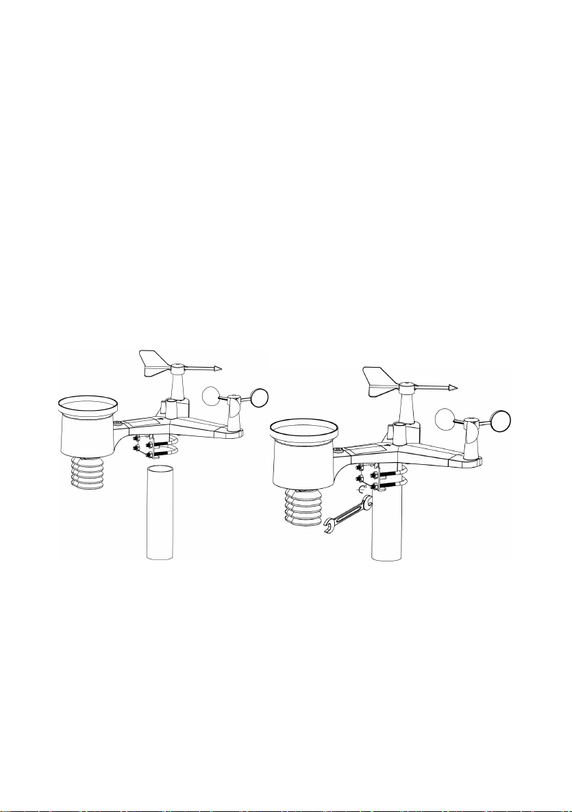
1. You must clean the rain gauge every few months and change
the batteries every 2-3 years. Provide easy access to the
weather station.
2. Avoid radiant heat transfer from buildings and structures. In
general, install the sensor array at least 5’ from any building,
structure, ground, or roof top.
3. Avoid wind and rain obstructions. The rule of thumb is to install
the sensor array at least four times the distance of the height of
the tallest obstruction. For example, if the building is 20’ tall, and
the mounting pole is 6’ tall, install 4 x (20 – 6)’ = 56’ away.
4. Wireless Range. The radio communication between receiver
and transmitter in an open field can reach a distance of up to
100 meters, providing there are no interfering obstacles such as
buildings, trees, vehicles, high voltage lines. Wireless signals
will not penetrate metal buildings. Under most conditions, the
maximum wireless range is 100’.
5. Radio interference such as PCs, radios or TV sets can, in the
worst case, entirely cut off radio communication. Please take
this into consideration when choosing console or mounting
locations. Make sure your display console is at least five feet
away from any electronic device to avoid interference.

5
5. Setting Started
5.1 Contents
QTY
Item
1
Display Console
1
Yshape outdoor sensor (Thermo-hygrometer / Rain
Gauge / Wind Speed Sensor /Transmitter)
1
Wind Vane
1
5V DC Adapter
1
U-bolt with mounting clamps
1
User manual
1
Zip bag for 1pc 10mm single-head wrench
5.2 Sensor Set Up
1. Wind Vane
2. Wind Speed Sensor
3. UV sensor/ Light sensor
4. Thermo-hygro sensor
5. Rain collector
6. Bubble level
7. Solar panel
8. U-Bolt
9. Battery compartment
10. Reset button
11. LED Indicator: light on for 4s if the unit power up. Then the LED will
flash once every 16 seconds (the sensor transmission update period).

6
5.2.1 Install U-bolts and mounting pole
Installation of the U-bolts, which are in turn used to mount the sensor
package on a pole, requires installation of an included metal plate to
receive the U-bolt ends. The metal plate, visible in Figure 1, has four
holes through which the ends of the two U-Bolts will fit. The plate itself is
inserted in a groove on the bottom of the unit (opposite side of solar
panel). Note that one side of the plate has a straight edge (which goes
into the groove), the other side is bent at a 90-degree angle and has a
curved profile (which will end up “hugging” the mounting pole). Once the
metal plate is inserted, remove nuts from the U-Bolts and insert both
U-bolts through the respective holes of the metal plate as shown in
Figure 8.
Figure 1
Loosely screw on the nuts on the ends of the U-bolts. You will tighten
these later during final mounting. Final assembly is shown in Figure 9.
Figure 2
The plate and U-Bolts are not yet needed at this stage but doing this
now may help avoid damaging wind vane and wind speed cups later on.

7
5.2.2 Install wind vane
Push the wind vane onto the shaft on the top of the sensor, until it stop
moving further, as shown in figure 3.
Tighten the set screw, with a Philips screw driver(size PH0), until the
wind van cannot be removed from the axle, as shown in figure 4. Make
sure the wind vane spin freely. The wind vane’s movement has a small
amount of friction, which is helpful in providing steady wind direction
measurements.
Figure 3 Figure 4
There are four alphabet letter of “N”, ”E”, ”S”and “W” around the wind
direction, representing for the direction of North, East, South and West.
Wind direction sensor has to be adjusted so that the directions on the
sensor are matching with your real location. Permanent wind direction
error will be installation. when the wind direction sensor is not positioned
correctly during installation.
5.2.3 Install wind speed
Push the wind speed into the shaft as shown in figure 5.
Tighten the set screw with as shown in figure 5. Make sure the wind
speed can spin freely.
Figure 5 Figure 6

8
5.2.4 Install Rain Gauge
Keep the Indication mark in straight line. As show below photo.
5.2.5 Install Batteries
Insert 2XAA batteries in the battery compartment. The LED indicator on
the back of the transmitter will turn on for four seconds and normally
flash once every 16 seconds (the sensor transmission update period).
Figure 7 Figure 8
Note: If no LED light up or is permanently on, make sure the batteries
are inserted the correct way or a proper reset has happened. Do not
install the batteries backwards. You can permanently damage the
outdoor sensor
Note: We recommend 1.5V lithium batteries for cold weather
climates, but alkaline batteries are enough for most climates. We do
not recommend rechargeable batteries. They have lower voltages, they
do not operate well at wide temperature ranges, and do not last as
long, resulting in poorer reception.

9
5.2.6 Mount assembled outdoor sensor package
5.2.6.1 Before you mount
Before proceeding with the outdoor mounting detailed in this section,
you may want to skip to setup instructions in section 6.2 and onwards
first, while you keep the assembled outdoor sensor package nearby
(although preferably not closer than 5 ft. from the console). This will
make any troubleshooting and adjustments easier and avoids any
distance or interference related issues from the setup.
After setup is complete and everything is working, return here for
outdoor mounting. If issues show up after outdoor mounting they are
almost certainly related to distance, obstacles etc.
5.2.6.2 Mounting
You can attach a pipe to a permanent structure and then attach the
sensor package to it (see Figure 9). The U-Bolts will accommodate a
pipe diameter of 1-2 inches (pipe not included).
Figure 9 Figure 10
Finally,place the sensor package on top of the prepared mounting pipe
.The U-Bolts should be loose enough to allow this but loosen the nuts
as necessary.Once placed, hand tightens all four nuts, taking care to
do so evenly.
Now you will need to align the whole package in the proper direction by
rotating it on top ofthe mounting pipe as needed.Locate the arrow
labeled “North” that you will find on top of the sensor package right next
to the light sensor. Youmust rotate the whole sensor package until this
arrow points due north.

10
To achieve proper alignment, it is helpful to use a compass (many cell
phones have a compass application).
Once rotated in the correct orientation, lightly tighten the bolts a little
more (use a wrench) to prevent further rotation.
Note: Use the bubble level nextto the rain sensor to make sure sensor
array iscompletely level. Ifthe sensor isnot level, the rain gauge, UV
and solar radiation sensors will not measure properly.
5.2.7 Reset Button and Transmitter LED
In the event that the sensor array isnot transmitting, reset the sensor
array.
With an open ended paperclip, press and hold the RESET BUTTON
for three seconds to completely discharge the voltage.
Take out the batteries and wait one minute, while covering the solar
panel to drain the voltage.
Put batteries back in and resynchronize with console by powering
down and up the console with the sensor array about 3 meter away.
Figure 11

11
5.3 Best Practices for Wireless Communication
Note: To insure proper communication, mount the remote sensor(s)
upright on a vertical surface, such as a wall. Do not lay the sensor flat.
Wireless communication is susceptible to interference, distance, walls
and metal barriers. We recommend the following best practices for
trouble free wireless communication.
Electro-Magnetic Interference (EMI). Keep the console several feet
away from computer monitors and TVs.
Radio Frequency Interference (RFI). If you have other 433 MHz
devices and communication is intermittent, try turning off these other
devices for troubleshooting purposes. You may need to relocate the
transmitters or receivers to avoid intermittent communication.
1. Line of Sight Rating. This device is rated at 300 feet line of
sight (no interference, barriers or walls) but typically you will get
100 feet maximum under most real-world installations, which
include passing through barriers or walls.
2. Metal Barriers. Radio frequency will not pass through metal
barriers such as aluminum siding. If you have metal siding, align
the remote and console through a window to get a clear line of
sight.
The following is a table of reception loss vs. the transmission
medium. Each “wall” or obstruction decreases the transmission
range by the factor shown below.
Medium RF Signal Strength Reduction
Glass (untreated) 5-15%
Plastics 10-15%
Wood 10-40%
Brick 10-40%
Concrete 40-80%
Metal 90-100%

12
5.4 Display console
1. Insert the 5V AC adaptor into the back of the display console
Note: Place the outdoor sensor array about 5 to 10 feet from the
display console and wait several minutes for the remote sensors to
synchronize with the display console.
2. Insert 3 AAA batteries into the display console。Please insert the
battery as blew figure 12:
Figure 12
Note: The batteries are intended for back-up power only. The
backlight will remain on for 5 seconds when on back up battery
power only. Only when you use power adapter it will the back-light
be continuously on.
3. Keep both sensor and the display console together for 15 minutes
to lock in the sensor signals.
4. Spin the wind cups to simulate wind speed. Take the sensor to the
sink and slowly drip water into the rain bucket to simulate rain.
5. After 15miuntes, follow the mounting instructions for proper
placement of sensors.

13
Figure 13
Note: Your display console should have readings in all sections. Wind
and Rain will show 0’s (connected) until wind or rain occur or are
simulated.
Note: If you only use battery to power up display console, you must
press LIGHT/SNOOZE key to light up the LCD before press any other
key.

14
5.4.1 Vertical Desk Stand
The console is best viewed above from a 20 to 30 degree angle.
In addition to the fold out desk stand on the back of the display, console,
the console also includes a vertical desk stand to improve the viewing
able on a desk, as shown in Figure 14.
Figure 14

15
6. Display Console Operation
6.1 Screen Display
1.Time 10. Rain fall
2.Moon phase 11. Outdoor temperature
3. Barometric Pressure 12. Outdoor humidity
4. Weather forecast 13. RF icon
5. UV index 14. Indoor humidity
6. Light 15. Indoor temperature
7. Wind speed 16. Date
8. Wind direction 17. WIFI icon
9. MAX/MIN Daily 18. DST

16
6.2 Initial Display Console Set Up
Connect the power adapter to power up the display console.
The unit will show software version number 2 seconds after power
reset.
The unit will turn on all segments of the LCD for 3 seconds after power
reset, the unit will start to register the outdoor channel for 3 minutes.

17
6.3 Key function
The console has eight keys for easy operation
Key
Description
SET
Press this key to view MAC address.
Hold this key to enter setting mode
TEMP.
Press this key to view wind Chill, Heat Index, Dew Point
Temperature
RAIN
Press this key to view Rain Rate, event, Rain Day, Rain
Week, Rain Month, and Rain total
Press the RAIN key 2s to reset current display rain
WIND +
Press this key to view wind/gust and wind direction
PRESSURE
Press this key to view Absolute Pressure average of
12hr, 24hr, 48hr and 72hr
Press and hold 2s this key to view the absolute and
relative pressure
ALARM
Press this key to view the alarm value of Temperature /
Humidity/rain rate/rain day/wind
MAX/MIN
Press this key to view the MAX/MIN value of
Temperature / Humidity/rain rate/rain
day/wind/UVI/LIGHT/Absolute Pressure
LIGHT
/SNOOZE
Press this key to adjust LCD backlight brightness:
HI/MID/OFF
Hold this key to register new transmitter
Note:
1) When power on, press WIND/+ and PRESSURE /- key to reset the
weather station and clear all records memory, and clears all user
settings to default.
2) When power on, press TEMP. key to skip receive RF signal.
3) In Setting mode,pressing WIND/+ or PRESSURE/-key select the
unit or scrolls the value; keeping press and holding WIND/+ or
PRESSURE/-key for 2 second will increase/decrease digits in
great steps.
4) The setting procedure can be exited at any time by either pressing
the LIGHT /SNOOZE key or waiting for the 30-second time-out to
take effect.

18
6.4 Setting mode
Pressing the SET key for 2 seconds to enter setting model,the basic
settings can now be performed in the following order:
6.4.1 BEEP:
-Press the SET key for 2 seconds to select the beep section, ON/OFF
section digits will start flashing, press the WIND/+ or PRESSURE/-
key to select ON or OFF.
“BEEP ON” will make the Beep sound on every key press. If you do not
want the beep sound to be heard, select “BEEP OFF”
6.4.2 MAX/MIN Daily:
-Press the SET key twice to select the MAX/MIN Daily section,
ON/OFF section digits will start flashing, press the WIND/+ or
PRESSURE/-key to select ON or OFF . (Default is ON,ON: clear at
0:00 every day).
6.4.3 Time / Date
- Press the SET key third time to select the 12/24 hour format section
(default: 24hr).
-Press the SET key forth time to select the hour section.
-Press the SET key fifth time to select the minutes section.
-Press the SET key sixth time to select DD-MM or MM-DD format.
(Default DD-MM format)
-Press the SET key seventh time to select year.
-Press the SET key eighth time to select month.
-Press the SET key ninth time to select day.

19
Note: Press the WIND/+ or PRESSURE/-key to set the value.
Note: If user to change minute value, second will auto clear to 0.
Note: WIFI firmware version 1.4.4 and above support Global Time
synchronization. Time zone, DST and date will automatic updated from
internet when base station is connected to WIFI internet.
6.4.4 Pressure
-Press the SET key tenth to select the ABS pressure unit, pressure
value and hPa digits will start flashing, press the WIND/+ or
PRESSURE/-key to select unit (hPa, inhg,mmhg)
-Press the SET key eleventh to select the REL pressure unit, pressure
value and hPa digits will start flashing, press the WIND/+ or
PRESSURE/-key to select unit (hPa, inhg,mmhg)
1) Viewing Absolute vs. Relative Pressure
To switch between absolute and relative pressure, press and hold the
[PRESSURE -] button for two seconds.
Absolute pressure is the measured atmospheric pressure, and is a
function of altitude, and to a lesser extent, changes in weather
conditions.
Absolute pressure is not corrected to sea-level conditions.
Relative pressure is corrected to sea-level conditions.
2) Rate of Change of Pressure Graph
The rate of change of pressure graphic is shown to the left of the
barometric pressure and signifies the difference between the daily
average pressure and the 30 day average (in hPa).

20
3) Viewing Pressure History
Press the [PRESSURE -] button to view the 12 hour, 24 hour, 48 hour
and 72 hour pressure average.
4) Relative Pressure Calibration Discussion
To compare pressure conditions from one location to another,
meteorologists correct pressure to sea-level conditions. Because the air
pressure decreases as you rise in altitude, the sea-level corrected
pressure (the pressure your location would be at if located at sea-level)
is generally higher than your measured pressure.
Thus, your absolute pressure may read 28.62 inHg (969 mb) at an
altitude of 1000 feet (305 m), but the relative pressure is 30.00 inHg
(1016 mb).
The standard sea-level pressure is 29.92 inHg (1013 mb). This is the
average sea-level pressure around the world. Relative pressure
measurements greater than 29.92 inHg (1013 mb) are considered high
pressure and relative pressure measurements less than 29.92 inHg are
considered low pressure.
To determine the relative pressure for your location, locate an official
reporting station near you (the internet is the best source for real time
barometer conditions, such as Weather.com or Wunderground.com),
and set your weather station to match the official reporting station.

21
6.4.5 Light
-Press the SET key 12th time to select light unit (lux, fc, w/m2;default:
w/m2).
6.4.6 Temperature
-Press the SET key 13th time to select in/outdoor temperature unit,
degree C digits will start flashing, press the WIND/+ or PRESSURE/-
key to select unit (C or F; default: C).
-In normal mode, press the T E M P. key to view wind Chill, Heat Index,
Dew Point Temperature. Press the T E M P. key for 5 second, will register
new transmitter.
Note: every 60 second the unit will measure indoor temperature, indoor
humidity and pressure. If temperature is to lower than minimum range,
will display --.-, if it is higher than highest range, will display --.-.
6.4.7 Wind speed
-Press the SET key 14th to select wind speed unit ( km/h, mph, knots,
m/s, bft;default: km/h ).
-In normal mode,press and release the WIND/+ key to view the wind,
gust and wind direction.
6.4.8 Rain
-Press the SET key 15th to select rainfall unit ( inch or mm) the default
mode is mm).
Table of contents
Other PRO SIGNAL Weather Station manuals
Popular Weather Station manuals by other brands

La Crosse Technology
La Crosse Technology 308-1417BLV2 instruction manual

Oregon Scientific
Oregon Scientific RGR126N user manual

FuehlerSysteme eNET International
FuehlerSysteme eNET International Compact FS6003 Instructions for use

La Crosse Technology
La Crosse Technology WS-8610 instruction manual

Ambient Weather
Ambient Weather WS-1171A user manual

TFA
TFA 35.1121 IT Square Plus instruction manual