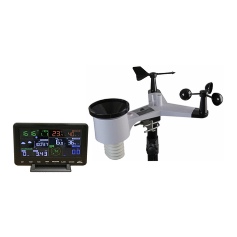
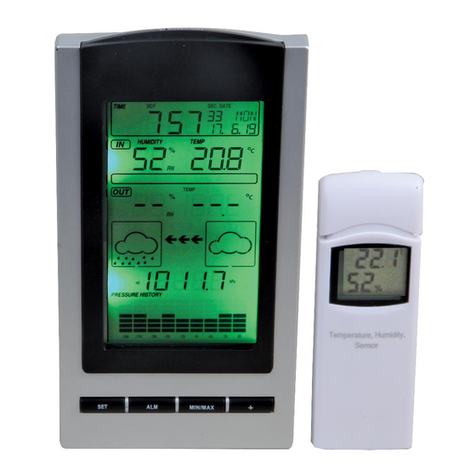
PRO SIGNAL PSG04174 User manual

yDo not expose the main unit to rain or moisture
yUse only recommended batteries
yRemove the batteries if the weather station is not to be used for a
long time. Old batteries can begin to leak and damage the product.
yRemember to insert the batteries according to the markings in the
battery compartment. The wrong polarity (+/-) can damage the
weather station.
yDamage that has occurred by careless handling is not covered by
the warranty.
Production Description.
yDisplay of indoor and outdoor temperature, wind speed, wind
direction, humidity, rainfall amounts, time and date
yAlarm function for certain weather conditions as well as records of
1
Wireless Weather Station
Model: PSG04174
Safety

all minimum and maximum values along with time and date of their
recordings
yRadio control time and date (DCF/WWVB/MSF version optional
but only one)
ySave the data when batteries is changed
yOperates on 5x LR6/AA alkaline batteries (not included)
Contents
yMain unit (Display unit)
yOutdoor unit
LCD Display
The following illustration shows the full segments of the LCD for
description purpose only and will not appear like this during normal
operation and use.
2

1. Time alarm on icon
2. DST icon (only available on
WWVB version)
3. RCC tower icon for time reception
4. Date of the week/time zone
5. Date
6. Wind direction alarm
7. General Max record
8. Wind direction
9. General Min. record
10. Rainfall high alarm
11. Indoor temperature high alarm
and low alarm
12. Temperature unit
13. Indoor temperature
14. Indoor humidity high alarm and
low alarm
15. Indoor humidity
16. Rainfall unit
17. Outdoor temperature high
alarm and low alarm
18. Outdoor temperature
19. Outdoor reception signal
20. Outdoor Humidity
21. Outdoor transmitter low
battery indicator
22. Outdoor humidity high alarm
and low alarm
23. Rainfall
24. Rainfall 1h,24h, week,
month or total display
25. Wind speed
26. Wind speed unit
27. Wind speed high alarm
28. Time
Note: The presence of the "Alarm-On icon" in the section means that
the particular alarm has been enabled.
3

Set up Guide
Figure 1
Figure 2
1. Wind Speed Sensor
2. Wind Vane
3. Thermo-hygro sensor
4. Rain collector
5. Bubble level
6. Solar panel
7. Antenna
8. U-Bolt
9. Battery compartment
10. Reset button
11. LED Indicator: lights for 4 seconds when the unit powers up.
Then the LED will flash once every 48 seconds (the sensor
transmission update period).
4
6
8
910
11
7

1. Install U-bolts and metal plate
Installation of the U-bolts, which are used to mount the sensor
package on a pole, requires installation of an included metal plate
to receive the U-bolt ends. The metal plate, visible in Figure 3 has
four holes through which the ends of the two U-Bolts will fit. The
plate itself is inserted in a groove on the bottom of the unit . Note
that one side of the plate has a straight edge (which goes into the
groove), the other side is bent at a 90-degree angle and has a
curved profile (which will end up “hugging” the mounting pole).
Once the metal plate is inserted, insert both U-bolts through the
respective holes of the metal plate as shown in Figure 3.
Figure 3: U-Bolt installation
Loosely screw on the nuts on the ends of the U-bolts. You will
tighten these later during final mounting. Final assembly is shown in
Figure 4.
Figure 4: U-Bolts and nuts installed
The plate and U-Bolts are not yet needed at this stage but doing
this now may help avoid damaging wind vane and wind speed cups
later on. Handling of the sensor package with wind vane and speed
5

cups installed to install these bolts is more difficult and more likely
to lead to damage.
2. Install wind speed cups
Push the wind speed cup assembly onto the shaft on the top side of
the sensor package, as shown in Figure 5 on the left side. Tighten
the set screw, with a Philips screwdriver (size PH0), as shown on
the right side. Make sure the cup assembly can rotate freely. There
should be no noticeable friction when it is turning.
Figure 5: Wind speed cup installation diagram
3. Install wind vane
Push the wind vane onto the shaft on the opposite side of the wind
cups, until it goes no further, as shown on the left side in Figure 6.
Next, tighten the set screw, with a Philips screwdriver (size PH0), as
shown on the right side, until the wind vane cannot be removed
from the axle. Make sure the wind vane can rotate freely. The wind
vane’s movement has a small amount of friction, which is helpful in
providing steady wind direction measurements.
6

Figure 6: Wind vane installation diagram
4. Install Batteries
Open the battery compartment with a screwdriver and insert 2 AA
batteries in the battery compartment. The LED indicator on the back
of the sensor package will turn on for four seconds and then flash
once every 48 seconds indicating sensor data transmission
(the sensor transmission update period).
Figure 7: Battery installation diagram
7

Note: If LED does not light up or is on permanently, make sure the
battery is inserted the correct way and inserted fully, starting over
if necessary. Do not install the batteries with incorrect polarity
as it may permanently damage the outdoor sensor.
Note: We recommend Lithium batteries for cold weather
climates, but alkaline batteries are sufficient for most climates.
Rechargeable batteries have lower voltages and should never be
used.
5. Mount outdoor sensor
Before you mount
Before proceeding with the outdoor mounting detailed in this section,
you may want to skip to the setup instructions first, while you keep the
assembled outdoor sensor package nearby (although preferably not
closer than 5 ft. from the console). This will make any troubleshooting
and adjustments easier and avoids any distance or interference related
issues from affecting the setup.
After setup is complete and everything is working, continue with
the outdoor mounting. If issues show up after outdoor mounting
they are almost certainly related to distance, obstacles etc.
Reference Figure 8, the mounting assembly includes two U-Bolts and a
bracket that tightens around a 1 to 2” diameter pole (not included) using
the four U-Bolt nuts.
Figure 8: Sensor package mounting diagram
8

Note
Beside the antenna, there is an arrow icon with an ident labelled
”WEST” (Figure 9) representing the direction of west.The sensor
body has to be adjusted so that the “WEST” indication is facing to real
west direction for your location. A compass device is recommended to
help adjust direction. Permanent wind direction error will be
introduced when the outdoor sensor is not installed in right direction.
Figure 9
Now look at the bubble level. The bubble should be fully inside the
red circle. If it is not, wind direction, speed, and rain readings may
not operate correctly or accurately. Adjust the mounting pipe as
necessary. If the bubble is close, but not quite inside the circle, and
you cannot adjust the mounting pipe, you may have to experiment
with small wooden or heavy cardboard shims between the sensor
package and the top of the mounting pole to achieve the desired
result (this will require loosening the bolts and some
experimentation).
Make sure you check, and correct if necessary,the
westerly orientation as the final installation step, and now
tighten the bolts with a wrench.
6. Reset Button and Transmitter LED
Using a bent-open paperclip, press and hold the RESET BUTTON
(see Figure 10) to affect a reset: the LED turns on while the
RESET button is depressed, and you can now let go. The LED
should then resume as normal, flashing approximately once every
48 seconds.
9

RESET button
LED light
Figure 10
7. Best Practices for Wireless Communication
Note: To insure proper communication, mount the remote sensor(s)
upright on a vertical surface, such as a wall. Do not lay the sensor flat.
Wireless communication is susceptible to interference, distance, walls
and metal barriers. We recommend the following best practices for
trouble free wireless communication.
1. Electro-Magnetic Interference (EMI). Keep the console
several feet away from computer monitors and TVs.
2. Radio Frequency Interference (RFI). If you have other
433/868/915 MHz devices and communication is intermittent, try
turning off these other devices for troubleshooting purposes.
You may need to relocate the transmitters or receivers to avoid
intermittent communication.
3. Line of Sight Rating. This device is rated at 300 feet line of
sight (no interference, barriers or walls) but typically you will get
100 feet maximum under most real-world installations, which
include passing through barriers or walls.
4. Metal Barriers. Radio frequency will not pass through metal
barriers such as aluminum cladding.If you have metal cladding,
align the remote and console through a window to get a clear
line of sight.
10

The following is a table of reception loss vs. the transmission
medium. Each “wall” or obstruction decreases the transmission
range by the factor shown below.
Medium RF Signal Strength Reduction
Glass (untreated) 5-15%
Plastics 10-15%
Wood 10-40%
Brick 10-40%
Concrete 40-80%
Metal 90-100%
Receiver /Indoor unit
After inserting the batteries into the Weather Station, all LCD segments
will be turned on for a few seconds, all possible display segments are
turned on for checking.
After this, the weather station will make initial measurement and start to
register the transmitter (the radio reception icon will be turned on). Do
not press any key before outdoor sensor data received, otherwise the
outdoor sensor learning mode will be terminated. When outdoor
transmitter has been registered, the base station will automatically
switch to the normal display mode from which all further settings can be
performed by the user.
If no RCC signal is detected in the initial setup, the transmitter will try
once every two hours to get an RCC signal until a signal is received.
Once the transmitter receives the RCC signal it will transmit the signal
to the monitor. On the monitor the RCC tower icon will be displayed, if
the monitor doesn’t receive the RCC signal or loses the signal
continuously for 12 hours the RCC icon will not be display.
11

Note for RCC signal:
The best condition for reception is at night, between midnight and
6:00am – when there is less atmospheric interference.
Note:
If a battery change on the transmitter alone is made, the receiver will
be resynchronized to the transmitter again within the next 3 hours. If
you want to shorten the receiving data time, the base station also has
to re-install the battery so that it can have the new security code learnt
right way, but the previous weather data and alarm value settings in
receiver will be lost.
Note:
Commonly the radio communication between receiver and transmitter
in the open field can reach a distance of up to 330 feet providing that
there are no interfering obstacles such as buildings, trees, vehicles,
high voltage lines, etc.
Radio interferences such as PC screens, radios or TV sets can, in
bad cases, entirely cut off radio communication. Please take this into
consideration when choosing standing or mounting locations.
Program Mode
The base station has five keys for easy operation: SET key,+key,
HISTORY key,ALARM key,MIN/MAX key
Note:
When setting certain units in the manual setting mode, hold the +or
MIN/MAX key for 2s will increase/decrease digits in greater steps.
The setting procedure can be exited at any time by either pressing the
HISTORY key or waiting for the 30-second time-out to take effect.
12

Quick Display Mode
-While in normal display, Press the SET key to enter the Quick Display
Mode as follow:
yWind speed / Gust speed (press the +key or MIN/MAX key shifts
the display between the wind speed and gust speed)
y1 hour / 24 hour / week / month / total rainfall quantity (press the +
key or MIN/MAX key shifts the display between the selectable
rainfall quantities), while display the rainfall total quantity, pressing
the SET key for 2 seconds will reset the rainfall total value to zero.
yOutdoor Temperature / Wind chill / Dew point (press the +key or
MIN/MAX key shifts the display between outdoor temperature,
wind chill and dew point)
Press the SET key to accept the change and advance to the next
display mode. Continue to press the SET key to toggle through the
display mode until return to the normal Mode
Setting Mode
-Press the SET key for 2 second while in normal mode to enter the
Setting mode, LCD contrast digits will start flashing. You can skip over
any setting by press the SET key.Press +key orMIN/MAX key to
select the units or scrolls the value. Holding the +key or MIN/MAX key
for 2 second will increase/decrease digits in great steps. To exit the
Setting mode at any time, press the HISTORY key.
yTime Zone Setting (-12Æ12)
Note: At Europe, 0 for GMT+1 time zone, 1 for GMT+2 time zone,
-1 for GMT time zone. At America, -4 for Atlantic Time zone, -5 for
Eastern Time zone, -6 for Central Time zone, -7 for Mountain Time
zone, -8 for Pacific time zone, -9 for Alaska time zone, -10 for
Hawaii time zone.
y12/24h time display select.
yManual time setting (hours/minutes)
ySelect DD-MM or MM-DD format.
yCalendar setting(year /month/ date)
yWind speed and gust display units in km/h, m/s, bft, mph, knots
yWind direction
yRainfall display units in mm or inch
13
·Temperature display unit degree Celsius or Fahrenheit
y

Calibration Mode
- Press the HISTORY key for 8 second while in normal mode to enter
the Calibration Mode, and the wind factor digits will start flashing.
You can skip over any setting by press the SET key. Press +key or
MIN/MAX key to select the units or scrolls the value. Holding the +
key or MIN/MAX key for 2 second will increase/decrease digits in
great steps. To exit the Calibration mode at any time, press the
HISTORY key.
yWind Speed Calibration (default is 1.0, adjustment range0.75 to
1.25)
yRainfall data Calibration (default is 1.0, adjustment range0.75 to
1.25)
yHistory rainfall Calibration
yOutdoor humidity Calibration
yOutdoor temperature Calibration
yIndoor humidity Calibration
yIndoor temperature Calibration
Wind Speed Calibration
Wind speed is the most sensitive to installation constraints. The
weather station should not be located close to buildings, trees or other
obstructions.
Many installations are not perfect and installing the weather station on
a roof can be difficult. Thus, you can calibrate for this error with a wind
speed multiplier.
In addition to the installation challenges, wind cup bearings (moving
parts) wear over time.
Without a calibrated source, wind speed can be difficult to measure.
We recommend using a calibrated wind meter and a constant speed,
high speed fan.
14

Temperature Calibration
Temperature errors can occur when a sensor is placed too close to a
heat source (such as a building structure, the ground and when placed
in direct sunlight without proper shielding in hot weather environments).
To calibrate temperature, we recommend a mercury or red spirit (fluid)
thermometer. Bi-metal (dial) and other digital thermometers are not a
good source and have their own margin of error. Using a local weather
station in your area is also a poor source due to changes in location,
timing (airport weather stations are only updated once per hour) and
possible calibration errors (many official weather stations are not
properly installed and calibrated).
Place the sensor in a shaded, controlled environment next to the fluid
thermometer, and allow the sensor to stabilize for 48 hours. Compare
this temperature to the fluid thermometer and adjust the console to
match the fluid thermometer.
Humidity Calibration
Humidity is a difficult parameter to measure accurately and drifts over
time. Humidity errors can occur when placed too close to the ground,
near grass or other sources of humidity.
The hygrometer sensor utilizes a capacitor, which varies as a function
of humidity. Due to manufacturing tolerances, the accuracy of the
sensor is ± 5%. To improve on this accuracy, the indoor and outdoor
humidity readings can be adjusted or calibrated from the display
console.
To calibrate humidity, you will need an accurate source, such as a
sling psychrometer or Humidipaks One Step Calibration kit.
Rainfall calibration
The Rain Collector is calibrated at the factory so the bucket tips (and
records rainfall) for each 0.01" (or 0.3 mm) of rain. To calibrate rainfall,
we recommend a tube type rain gauge. Use a rain gauge with an
aperture of at least 4 inches. Any smaller and the readings obtained
15

may not be accurate. Place the tube type rain gauge directly next to
the rain collector. Compare the totals on three storms. Based on this,
develop an average for how far off the readings are.
Do not compare rainfall readings to reading obtained from television,
radio, newspapers, or neighbors’ readings. Such readings are not
located in your specific environment and therefore are not an accurate
measurement of the weather readings taking place in your
surroundings. The rain collector is carefully tested at the factory to
conform to the specifications listed in the back of this manual.
The history rainfall calibration factor is applied to the running total, not
individual tips. All of the rainfall figures are calculated from the total
number of tips recorded by the station since it was reset. The total is
multiplied by 0.3 to get a total in mm. This is then converted to inches if
necessary by multiplying by 0.0393700787. The calibration multiplier is
then applied to this, and this is the figure that remembers and
compares each time a new total is read from the station.
History Modes
- While in Normal Mode, press the HISTORY key to enter the History
Mode.
-In the history mode, press SET key will trigger the history clear
procedure: the word of “CLEAR” will be flashing, hold the SET key
for 2 seconds will clear all the history records.
-In the history mode, press the MIN/MAX key to select the record
over the past 24hours at increments of -3 hours, -6 hours, -9 hours,
-12 hours, -15 hours, -18 hours, -21 hours, -24 hours.
Press the HISTORY key or wait for 30 secondsto return to Normal
Mode
Alarm Modes
- While in Normal Mode press the ALARM key to enter the High
Alarm Mode, Press the ALARM key again to enter Low Alarm mode,
press the ALARM key the third time to return the Normal Mode.
16

Remark: after the initial pressing of ALARM key, the display will be
refreshed to show current high, low alarm values. Normal alarm value
will be displayed only for those already activated, all other not activated
values will be displayed with “- - -“or “- -“instead.
-In the High Alarm Mode press the SET key to select the following alarm
modes:
1. Time alarm
2. Wind speed high alarm (0-50m/s)
3. Gust speed high alarm (0-50m/s)
4. Wind direction alarm
5. 1Hour rain high alarm (0-999.9mm)
6. 24 hour rain high alarm (0-999.9mm)
7. Outdoor humidity high alarm (1%-99%)
8. Outdoor temperature high alarm (-40˚C--60˚C)
9. Wind chill high alarm (-40˚C--60˚C)
10. Dew point high alarm (-40˚C--60˚C)
11. Indoor humidity high alarm (1%-99%)
12. Indoor temperature high alarm (-9.9˚C--60˚C)
-In the Low Alarm Mode press the SET key to select the following alarm
modes:
1. Time alarm
2. Outdoor humidity low alarm (1%-99%)
3. Outdoor temperature low alarm (-40˚C--60˚C)
4. Wind chill low alarm (-40˚C--60˚C)
5. Dew point low alarm (-40˚C--60˚C)
6. Indoor humidity low alarm (1%-99%)
7. Indoor temperature low alarm (-9.9˚C--60˚C)
-In the alarm modes, press +key or MIN/MAX key to change or scroll
the alarm value.
Hold the +key or MIN/MAX key for 2 second will increase/decrease
digits in great steps. Press the ALARM key to select the alarm on or off
17

(if alarm is enabled, the speaker icon on the LCD will be turned on
indicating the alarm function has been enabled).
- Press the SET key to toggle through each alarm mode until it returns
to the normal display mode.
-Press HISTORY key or key idle 30 second at any time, the alarm
mode will return to Normal Mode
Canceling the Temperature Alarm While Sounding
a. When a set weather alarm condition has been triggered, that
particular alarm will sound for 120 second and flash until the weather
condition doesn’t meet the user set level. Press any key to mute the
alarm. When weather alarm condition was activated again within 3
hours, alarm will not sound but will continue to flash until weather
conditions have become more steady. This feature is useful to avoid
repeated triggering for the same alarm value.
b. The alarm will reactivate automatically once the value has fallen
below the set value.
Min/Max Mode
- While in Normal Mode, press the MIN/MAX key to enter the maximum
mode
-Press MIN/MAX key again to enter the minimum mode
-Press MIN/MAX key again to return the Normal Mode.
-In the maximum reading Mode, press the +key to display the
following maximum values together with the time and date stamp when
these values were recorded, if hold the SET key for 3s in the following
individual maximum value will be reset to current reading together with
the current time and date.
18

1. Wind speed maximum
2. Gust speed maximum1Hour rain maximum
3. 24 hour rain maximum
4. Week rainfall maximum
5. Month rainfall maximum
6. Outdoor humidity maximum
7. Outdoor temperature maximum
8. Wind chill temperature maximum
9. Dew point temperature maximum
10. Indoor humidity maximum
11. Indoor temperature maximum
- In the minimum reading Mode, press the +key to display the following
minimum values together with the time and date at which these values
were recorded, if hold the SET key for 3s in the following individual
minimum value will be reset to current reading together with the current
time and date.
1. Outdoor humidity minimum
2. Outdoor temperature minimum
3. Wind chill temperature minimum
4. Dew point temperature minimum
5. Indoor humidity minimum
6. Indoor temperature minimum
-Press the HISTORY key or wait 30 seconds, the MIN/MAX mode will
return to Normal Mode
Reset To Factory Default Settings
While in normal display, press and hold the +key for 20 seconds
to reset all settings to the manufacturer default setting.
19

Specifications
Outdoor data
Transmission distance in open field : 100m(300 feet)
Frequency
Temperature range
Accuracy
Resolution
Measuring range rel. humidity
Accuracy
Rain volume display : 0 – 9999mm (show --- if outside range)
Accuracy : + / - 10%
Resolution : 0.3mm (if rain volume < 1000mm)
: 1mm (if rain volume > 1000mm)
Wind speed : 0-180km/h (0~110mph) (show --- if outside range)
Accuracy: : +/- 1m/s (wind speed< 10m/s)
: +/-10% (wind speed > 10m/s)
Measuring interval thermo-hygro sensor
Water proof level
Indoor data
Measuring interval temperature/humidity
Indoor temperature range
--- if outside range)
Resolution
Measuring range rel. humidity
Resolution
Alarm duration
: 30 seconds
: 0˚C--50˚C (14℉to + 140℉)
: 0.1˚C
:10%~99%
:1%
:120 sec
Power consumption
Base station
Remote sensor
:3 x AA 1.5V LR6 Alkaline batteries (not included)
: 2 x AA 1.5V LR6 Alkaline batteries (not included)
20
: 48 seconds
: IPX3
: 868Mhz
: -40˚C—60˚C (-40 to +149℉℉)
: + / - 1 °C
: 0.1˚C
: 10%~99%
: +/- 5%
Table of contents
Other PRO SIGNAL Weather Station manuals
Popular Weather Station manuals by other brands

Levenhuk
Levenhuk Wezzer PLUS LP60 user manual

La Crosse Technology
La Crosse Technology T83653v2 manual

Oregon Scientific
Oregon Scientific BA812E user manual

Technoline
Technoline WS9767 instruction manual

Technoline
Technoline WS 9172 instruction manual

La Crosse Technology
La Crosse Technology WEATHER DIRECT WD-3103U owner's manual

La Crosse Technology
La Crosse Technology CA84688 Faqs

TFA
TFA ERGO 30.3014 instruction manual

HoMedics
HoMedics EnviraStation DWS-170 Instruction manual and warranty

La Crosse Technology
La Crosse Technology 308A-146 user manual

Oregon Scientific
Oregon Scientific RAR502X user manual

LEGRAND
LEGRAND Netatmo user manual