Pro-Star 1K User manual

HIGH FREQUENCY ONLINE UPS
USER MANUAL
1KVA/2KVA/3KVA/6KVA/10KVA
PF 1.0


Table of Contents
CHAPTER 1 SAFETY INSTRUCTIONS ..........................................................................................................................1
1.1 About This Manual .......................................................................................................................................... 1
1.2 Transportation ..................................................................................................................................................1
1.3 Preparation ....................................................................................................................................................... 1
1.4 Installation ........................................................................................................................................................1
1.5 Operation .......................................................................................................................................................... 2
1.6 Maintenance ..................................................................................................................................................... 2
1.7 Deenergizing Safety ........................................................................................................................................3
1.8 Standards ..........................................................................................................................................................3
CHAPTER 2 SYMBOLS DESCRIPTION ......................................................................................................................... 4
2.1 General Introduction ....................................................................................................................................... 4
2.2 Symbols Information .......................................................................................................................................4
CHAPTER 3 INSTALLATION AND SETUP .................................................................................................................... 5
3.1 Unpacking and Inspection ..............................................................................................................................5
3.2 Product Rear View ........................................................................................................................................... 5
3.3 Rack Mount UPS Installation ....................................................................................................................... 12
3.4 Setup the UPS ................................................................................................................................................ 12
CHAPTER 4 OPERATION ..............................................................................................................................................17
4.1 Button Operation ........................................................................................................................................... 17
4.2 LCD Display Icons ..........................................................................................................................................18
4.3 LED Indicators ................................................................................................................................................19
4.3 Audio Alarm .................................................................................................................................................... 20
4.4 UPS Working Status ...................................................................................................................................... 20
4.5 LCD Display Information .............................................................................................................................. 20
4.6 UPS Operation ................................................................................................................................................22
4.7 UPS Setting ..................................................................................................................................................... 25
4.8 Operation Mode Description ........................................................................................................................ 29
4.9 Fault and Alarm Information ........................................................................................................................30
4.10 UPS Parallel.................................................................................................................................................. 31
CHAPTER 5 TROUBLESHOOTING .............................................................................................................................. 33
CHAPTER 6 STORAGE AND MAINTENANCE ............................................................................................................ 35
6.1 Prior to Installation ........................................................................................................................................35
6.2 After Usage .....................................................................................................................................................35
CHAPTER 7 SPECIFICATIONS .................................................................................................................................... 36
7.1 Specification of Tower Type UPS 1KVA - 3KVA ......................................................................................... 36
7.2 Specification of Tower Type UPS 6KVA - 10KVA .......................................................................................37
7.3 Specification of Rack Mount UPS 1KVA - 3KVA.........................................................................................39
7.4 Specification of Rack Mount UPS 6KVA - 10KVA ...................................................................................... 40
7.5 Specification of Rack Mount Battery Pack ................................................................................................. 41

1
CHAPTER 1 SAFETY INSTRUCTIONS
1.1 About This Manual
Purpose
Please comply with all warnings and operating instructions in this manual strictly. Save this manual
properly and read carefully the following instructions before installing the unit.
Scope
This manual provides safety and installation guidelines as well as information on wiring.
1.2 Transportation
Transport the unit only in suitable packaging to protect it from jolts and shocks. The UPS must be kept
upright at all times and handled with care.
1.3 Preparation
Condensation may occur if the UPS system is moved directly from cold to warm environment. The UPS
system must be absolutely dry before being installed. Please allow at least two hours for the UPS
system to acclimate the environment.
Do not install the UPS system near water or in moist environments.
Do not install the UPS system where it would be exposed to direct sunlight or near heater.
Do not block ventilation holes in the UPS housing.
1.4 Installation
Do not connect appliances or devices which would overload the UPS system (e.g. laser printers) to
the UPS output sockets or terminals.
Place cables in such a way that no one can step on or trip over them.
Do not connect domestic appliances such as hair dryers to UPS output sockets.
The UPS can be operated by any individuals with no previous experience.
Connect the UPS system only to an earthed shockproof outlet which must be easily accessible and
close to the UPS system.
When installing the equipment, it should ensure that the sum of the leakage current of the UPS
and the connected devices does not exceed 3.5mA.

2
1.5 Operation
Do not disconnect the mains cable on the UPS system or the building wiring outlet (shockproof
socket outlet) during operations since this would cancel the protective earthing of the UPS system
and of all connected loads.
The UPS system features its own, internal current source (batteries). The UPS output sockets or
output terminals block may be electrically live even if the UPS system is not connected to the
building wiring outlet.
In order to fully disconnect the UPS system, first press the button to disconnect the
mains.
Prevent no fluids or other foreign objects from inside of the UPS system.
1.6 Maintenance
The UPS system operates with hazardous voltages. Repairs may be carried out only by qualified
maintenance personnel.
CAUTION - risk of electric shock.
Even after the unit is disconnected from the mains (building wiring outlet), components
inside the UPS system are still connected to the battery and electrically live and
dangerous.
Before carrying out any kind of service and/or maintenance, disconnect the batteries and verify that no
current is present and no hazardous voltage exists in the terminals of high capability capacitor such as
BUS-capacitors.
Only persons are adequately familiar with batteries and with the required precautionary measures may
replace batteries and supervise operations. Unauthorized persons must be kept well away from the
batteries.
CAUTION - risk of electric shock.
The battery circuit is not isolated from the input voltage. Hazardous voltages may occur
between the battery terminals and the ground. Before touching, please verify that no
voltage is present!

3
Batteries may cause electric shock and have a high short-circuit current. Please take the precautionary
measures specified below and any other measures necessary when working with batteries:
remove wristwatches, rings and other metal objects.
use only tools with insulated grips and handles.
When changing batteries, install the same number and same type of batteries.
Do not attempt to dispose of batteries by burning them. This could cause battery explosion.
Do not open or destroy batteries. Escaping electrolyte can cause injury to the skin and eyes. It may be
toxic.
1.7 Deenergizing Safety
The UPS contains internal batteries and may present a shock hazard even when disconnected from
branch circuit(mains). Before installing or servicing the equipment check that the:
Input circuit breaker in the OFF position.
Internal UPS batteries are removed.
1.8 Standards
* Safety
IEC/EN 62040-1
* EMI
Conducted Emission................................... :IEC/EN 62040-2
Category C3
Radiated Emission....................................... :IEC/EN 62040-2
Category C3
*EMS
ESD...................................................................:IEC/EN 61000-4-2
Level 4
RS.......................................................................:IEC/EN 61000-4-3
Level 3
EFT.................................................................... :IEC/EN 61000-4-4
Level 4
SURGE............................................................. :IEC/EN 61000-4-5
Level 4
CS.......................................................................:IEC/EN 61000-4-6
Level 3
Power-frequency Magnetic field.................:IEC/EN 61000-4-8
Level 4
Low Frequency Signals................................ :IEC/EN 61000-2-2
Warning: This is a product for commercial and industrial application in the second
environment-installation restrictions or additional measures may be needed to prevent disturbances.

4
CHAPTER 2 SYMBOLS DESCRIPTION
2.1 General Introduction
This series UPS, available in 1kVA, 2 kVA, 3 kVA, 6 kVA and 10 kVA, is an advanced online and
double-conversion UPS providing reliable and consistent pure sine-wave quality power to your
equipment. It supports personal computers, networks, servers, telecommunication equipment and a
variety of other facilities. It provides protection for electronic equipment from utility power blackouts,
brownouts, sags, surges, small utility power fluctuations and large disturbances. It also provides
battery backup power for connected equipment until utility power returns to acceptable levels or the
batteries are fully discharged.
Each model has internal batteries and can connect to the external battery pack (optional). The unit
provides output power factor up to 1.0, produces greater smoothly at all times.
2.2 Symbols Information
ICON
Information
ICON
Information
Pay attention
Ground
High voltage danger
Alarm cut off
Turn on UPS
Overload
Turn off UPS
Battery inspection
Function button
Repeat cycle
Page UP / Down
Do not place it with the sundries
Alternating current
Battery
Direct current

5
CHAPTER 3 INSTALLATION AND SETUP
There are two different types of online UPS: short-backup and long-run models. Please refer to the
following model table.
Model
Type
Model
Type
1K
Long-run Online UPS
1KB
Short-backup Online UPS
2K
2KB
3K
3KB
6K
6KB
10K
10KB
3.1 Unpacking and Inspection
Unpack the package and check the package contents. The shipping package contains:
●One UPS
●One user manual
●One battery cable (only for long-run models)
During UPS transportation, some unpredictable situations might occur. It is recommended that you
inspect the UPS’s exterior packaging. If you notice any damage, please immediately contact the dealer
from whom you purchased the unit.
NOTE: Before installation, please inspect the unit. Be sure that nothing inside the
package is damaged. Please keep the original package in a safe place for future use.
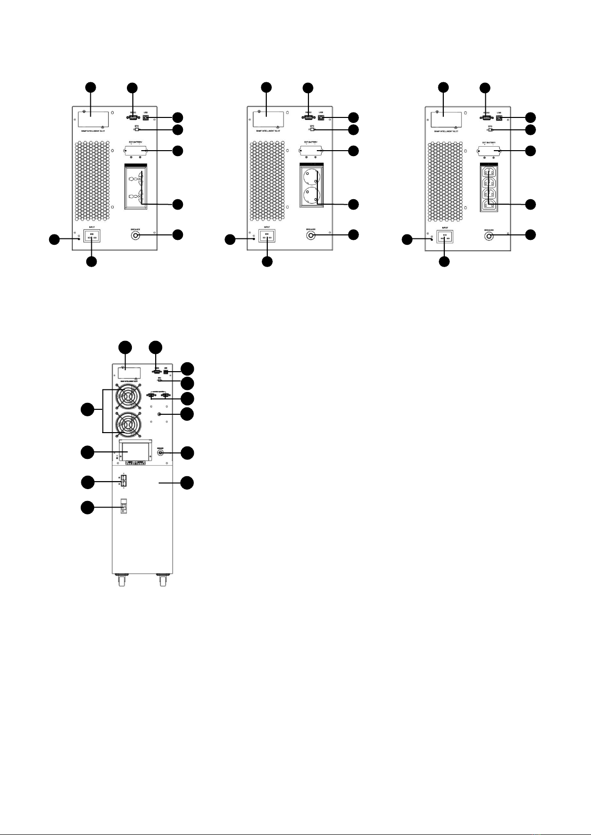
3.2 Product Rear View
3.2.1 Rear for Tower Type

6
1K
2K
3K
1
2
3
5
6
7
8
9
4
Universal Type
1
2
3
5
6
7
8
9
4
IEC Type
1
2
3
5
6
7
8
9
4
Schuko Type
Schuko Type
1
2
3
5
6
7
8
9
4
1
2
3
5
6
7
8
9
4
IEC Type
1
2
3
5
6
7
8
9
4
Universal Type
Schuko Type
1
2
3
5
6
7
8
9
4
Universal Type
1
2
3
5
6
7
8
9
4
IEC Type
1
2
3
5
6
7
8
9
4

7
6K-10K
1KB
2KB
1
2
3
5
6
7
8
9
4
Universal Type
1
2
3
5
6
7
8
9
4
IEC Type
1
2
3
5
6
7
8
9
4
Schuko Type
1
2
7
5
8
10
11
4
12
13
18
Universal Type
1
2
3
5
6
7
8
9
4
Schuko Type
1
2
3
5
6
7
8
9
4
IEC Type
1
2
3
5
6
7
8
9
4
8
3KB
6KB-10KB
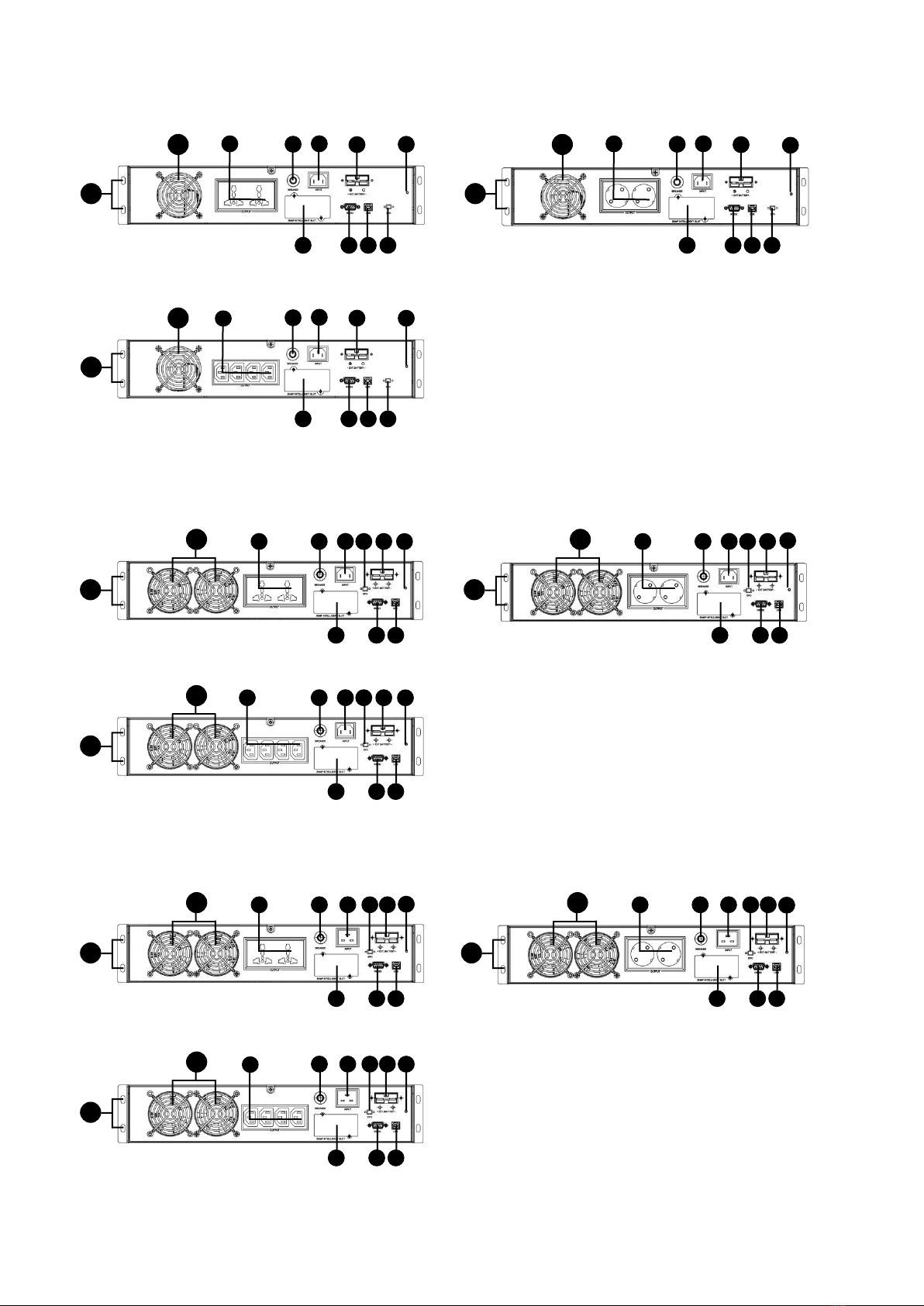
3.2.2 Rear for Rack Mount
Universal Type
3
5
6
7
8
1
2
9
4
Schuko Type
3
5
6
7
8
1
2
9
4
3
5
6
7
8
1
2
9
4
IEC Type
1
2
5
11
14
15
7
8
10
6
16
18
9
1K
2K
3K
1
2
6
7
3
5
8
9
11
17
Schuko Type
Universal Type
1
2
6
7
3
5
8
9
11
17
1
2
6
7
3
5
8
9
11
17
IEC Type
4
4
4
17
3
5
8
9
11
6
1
2
7
Schuko Type
17
3
5
8
9
11
6
1
2
7
Universal Type
17
3
5
8
9
11
6
1
2
7
IEC Type
4
4
4
17
3
5
8
9
11
6
1
2
7
Schuko Type
17
3
5
8
9
11
6
1
2
7
Universal Type
17
3
5
8
9
11
6
1
2
7
IEC Type
4
4
4

10
6K-10K
1KB
2KB
17
11
5
8
6
1
2
7
12
4
13
18
4
1
2
6
7
3
5
8
9
11
17
Schuko Type
1
2
6
7
3
5
8
9
11
17
Universal Type
1
2
6
7
3
5
8
9
11
17
IEC Type
4
4
4
17
3
5
8
9
11
6
1
2
7
Schuko Type
17
3
5
8
9
11
6
1
2
7
Universal Type
17
3
5
8
9
11
6
1
2
7
IEC Type
4
4
4

11
3KB
3.2.3 Rack Mount Battery Pack
17
5
15
2U Battery Pack
17
5
15
3U Battery Pack
1. Smart slot
2. RS-232 port
3. Output receptacles
4. Ground terminal
5. External battery connector (only for
long-run models, short backup models are
option)
6. Emergency power off connector (option)
7. USB port
8. Input circuit breaker
9. AC Input socket
10. Maintenance bypass switch (option)
11. Cooling fan
12. AC Input terminal
13. AC Output terminal
14. AC Input/Output terminal
15. Battery pack output circuit breaker
16. Battery bank
17. Rack mount hole
18. Parallel operation port (option)
17
3
5
8
9
11
6
1
2
7
Schuko Type
17
3
5
8
9
11
6
1
2
7
Universal Type
17
3
5
8
9
11
6
1
2
7
IEC Type
4
4
4
12
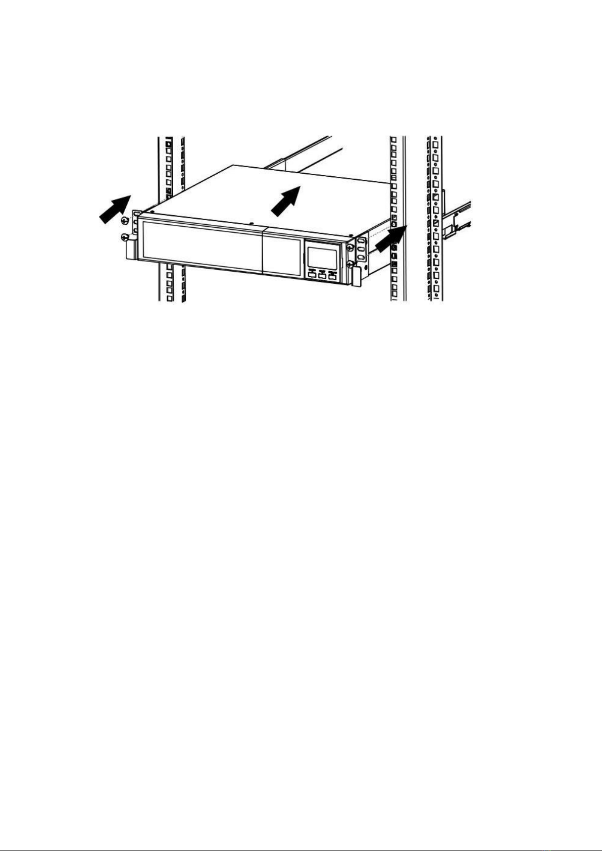
3.3 Rack Mount UPS Installation
This UPS can be mounted in the 19”rack chassis. Please follow below steps to position this UPS.
3.4 Setup the UPS
Before installing the UPS, please read below to select proper location to install UPS.
UPS should be placed on the flat and clean surface. Place it in an area away from vibration, dust,
humidity, high temperature, flammable liquids, gases, corrosive and conductive contaminants.
Install the UPS indoors in a clean environment, where it is away from window and door. Maintain
minimum clearance of 100mm in the bottom of the UPS to avoid dust and high temperature.
Maintain an ambient temperature range of 0ºC to 40ºC for UPS optimal operation. For every 5ºC
above 40ºC, the UPS will derate 10% of nominal capacity at full load.
It’s required to maintain maximum altitude of 1000m to keep UPS normal operation at full load UPS.
If it’s used in high altitude area, please reduce connected load.
It’s equipped with fan for cooling. Therefore, place the UPS in a well-ventilated area. It’s required
to maintain minimum clearance of 100mmin the front of the UPS and 300mm in the back and two
sides of the UPS for heat dissipation and easy-maintenance.
When connecting external battery bank or packs, please be sure to connect polarity correctly.
Connect positive pole of battery bank or pack to positive pole of external battery connector in UPS
and negative pole of battery bank or pack to negative pole of external battery connector in UPS.
Polarity misconnection will cause UPS internal fault. It’s recommended to add one breaker between
positive pole of battery pack and positive pole of external battery connector in UPS to prevent
damage to battery bank or packs from internal fault.
13
Prepare wires based on the following table:
Model
Wiring spec (AWG)
Input
Output
Battery
Ground
6KB
10
10
-
12
10KB
8
8
-
8
6K
10
10
10
12
10K
8
8
8
8
* NOTE 1: It is recommended to use suitable wire in above table or thicker for safety and efficiency.
* NOTE 2: The selections for color of wires should be followed by the local electrical laws and
regulations.
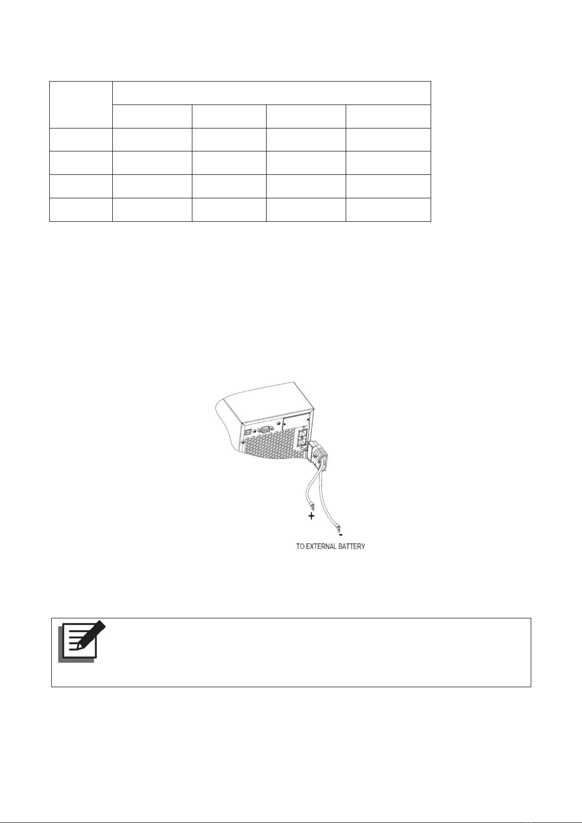
STEP 1: EXTERNAL BATTERY CONNECTION
If UPS is long-run model, please connect external batteries as below chart.
Tower type UPS external battery connection
Rack mount UPS external battery pack connection
Note:
Before connecting the external battery pack (optional) to the UPS, check whether the
rating voltage of the battery pack is suitable for the UPS.
(1) Set the battery pack’s DC breaker to the OFF position.
(2) Remove the cover of the external battery pack connector located on the rear side of the UPS.

14
(3) Connect the battery cable attached to the external battery pack (optional) to the UPS’s battery
pack connector.
(4) Set the battery pack’s circuit breaker to the ON position.
STEP 2: UPS INPUT CONNECTION
For Socket - Plug the UPS into a two-pole, three-wire and grounded receptacle only. Avoid using
extension cords.
For terminal connection - Remove the terminal block cover on the rear panel of UPS. Then connect
the wires according to the following terminal block diagrams: (Connect the earth wire first when
making wire connection.)
Input Line
Input Neutral
Ground

15
STEP 3: UPS OUTPUT CONNECTION
For socket-type outputs, simply connect devices to the outlets.
For terminal-type input or outputs, connection as below:
STEP 4: COMMUNICATION CONNECTION
Communication port:
USB Port
After connect UPS and computer by USB cable,you can use computer monitor UPS status by remote
control.
RS-232 Port
RS-232 interface is for the monitoring software and firmware update. UPS connect to monitor device
with RS-232 cable.
One end of RS-232 cable connects to computer RS-232 port.
One end of RS-232 cable connects to UPS RS-232 port.
Intelligent Slot
The UPS is equipped with intelligent slot perfect for either SNMP or AS400 card. It allows the UPS
communicate in a variety networking environment and with different types of devices. Before
installation, UPS must be turned off.
EPO (Emergency Power OFF)
It is option for 1KVA/2KVA/3KVA, and standard for 6KVA/10KVA. It is a green connector lays on the
UPS rear panel, we can shutdown UPS via remove EPO connector in the event of emergency. The EPO
wire connect diagram see below.
Ground
Output Neutral
Output Line
Intelligent slot
RS-232 port
USB port

16
STEP 5: TURN ON UPS
Press button on the front panel for two seconds to power on the UPS.
Note: The battery charges fully during the first five hours of normal operation. Do not
expect full battery run capability during this initial charge period.
STEP 6: INSTALL SOFTWARE
For optimal computer system protection, install UPS monitoring software to fully configure UPS
shutdown. You may insert provided CD into CD-ROM to install the monitoring software. If not, please
contact your local service to offer the software.
Pin 1 closed to pin 2, UPS shutdown
immediately. Pin 3 and pin 4 float.
1
Pin 1 and pin 2 are always connected.
When pin 3 and pin 4 disconnected, UPS
shutdown immediately.
2

17
CHAPTER 4 OPERATION
4.1 Button Operation
Button
Function
Turn on the UPS:
Press this combined button for at least 2 seconds to turn on the UPS.
Turn off the UPS:
Press this combined button at least 2 seconds to turn off the UPS.
This combined button has two functions. Please refer to the following for detailed
information.
1. Battery test:
Press this button at least 2 seconds to execute battery test in online mode.
2. Buzzer ON/OFF:
When the buzzer is on in battery mode/fault mode/battery test mode, press the
button for 1 second to turn off the buzzer. When the buzzer is off, press the button
for 1 second to turn on the buzzer.
This button has two functions. Please refer to the following for detailed
information.
1. Function setting:
Press this button at least 2 seconds to enter the function setting page, after
confirming the setting, press the button again for 2 seconds to back the main
page.
2. Confirm:
In setup mode, press the button for 0.1 second above to enter the item that you
want to set up or confirm your parameter setup.
Page up/down:
Press the button for 0.2 seconds to go to the previous/next display or to
increase/decrease number.
This manual suits for next models
13
Table of contents


