Pro-Weld ARC 1850 User manual
OPERATION/MAINTENANCE
MANUAL


ARC 1850
PRO WELD
PAGE
1.0
INTRODUCTION.......................................................
1
2.0
WARRANTY............................
...................................
1
3.0
UNPACKING YOUR UNIT.......................................
1
4.0
SUGGESTED SAFETY PREC
AUTIONS.......….......
1
4.1
PERSONAL SAFETY PRECAUTIONS…………….
1
4.2
POWER SUPPLY SAFETY PRECAUTIONS……..
2
5.0
GENERAL DESCRIPTI
ON..........................…...........
2
6.0
ELECTRICAL INPUT REQUIREMENT.......…........
2
7.0
CONTROL PANEL DESCRIPTION.....
........…........
4
8.0
WELD GUN SETUP.........................................…........
5
8.1
PLUNGE LENGTH....................
.................................
5
8.2
CHECKING GUN LIFT....................................….......
6
9.0
PARTS LIST..........
..........................................…........
7thru13
10.0
TROUBLE SHOOTING...................................….......
15
LIST OF FIGURES
1
JUMPER LINK ARRANGEMENT...................…......
3
2
CONTROL PANEL FRONT.........................…........
..
4
3
STANDARD GUN SET
-
UP..........................…............
5
4
FUSE BLOCK.................................................
..............
6
5
CONTROL UNIT
-
FRONT.........................................
7
6
CONTROL UNIT
-
REAR..........................
.................
8
7
CONTROL UNIT
-
SIDE VIEW................................
9
8
RECTIFIER, WELD BRIDGE ASSY................…...
...
10
9
PRINTED CIRCUIT BOARD ENCLOSURE.…......
11
10
GUN TIMER CONTROL PCB...................................
12
11
MONITOR PCB..
.........................................................
13
12
CURRENT CONTROL PCB..............................….....
14
TABLE OF CONTENTS
ARC 1850
PRO WELD
ARC 1850
PRO WELD
ARC 1850
PRO WELD

ARC 1850
PRO WELD

ARC 1850
PRO WELD
PAGE 1
1
.0 INTRODUCTION
Your new stud welding equipment has been carefully co
n-
structed using the finest components and material available.
Used properly, this equipment will give you many years of
profitabl
e, efficient service.
The system incorporates the latest in engineering advances
for complete, reliable end welding of mild ste
el, stainless
steel and aluminum fasteners.
A careful study of this manual will enable you to understand
how the welder operate
s to insure proper performance under
all conditions.
2.0 WARRANTY
The electrical and mechanical components of the stud
welder are thoroughly performance inspected prior to asse
m-
bly in the welder. The assembled welder is completely pe
r-
formance checked. The welder is delivered to you in fun
c-
tional electro
-mechanical condition.
All parts used in the assembly of the welder and its
accessories are fully warranted for
a period of 1 YEAR from
the date of delivery. In addition, the welding capacitors are
warranted for a period of 1 YEAR from the
date of delivery.
The printed circuit boards used in all proweld equipment are
warranted for a period of 3 years.
Under the wa
rranty, the manufacturer reserves the
right to repair or replace, at their option, defective parts
which fail during the guarant
ee period. Notice of any claim
for warranty repair or replacement must be furnished to the
manufacturer by the purchaser within
ten (10) days after the
defect is first discovered. The manufacturer does not assume
any liability for paying shipping cost or any labor or mater
i-
als furnished where such cost are not expressly authorized in
writing.
The manufacturer does not warrant any parts or acce
s-
sories against failures resulting from misuse, abuse, improper
installation, maladjustment, or use not in accordance with the
op
erating instructions furnished by the manufacturer. The
warranty is valid only when studs are purchased from sources
approved by the manufacturer or are of identical specific
a-
tions to the manufacturer’s
3.0 UNPACKING YOUR UNIT
Upon receipt of your unit, place it as close as possible to the
point of installation before unpacking it. Once the unit is u
n-
packed, it is recommended that you inspect it for any phys
i-
cal damage that may have occurred in shipping.
Y
our unit has been completely assembled and inspected at
the factory. Upon receipt, the unit must be hooked up to the
recommended
incoming power before welding.
Place the unit in a large enough area to provide adequate
ve
n
tilation. Do not restrict the air flow around the front lou-
vers or from the fan at the rear of the unit. Do not allow w
a-
ter to enter the unit in any way.
4.0 SUGGESTED SAFETY PRECAUTIONS
In any welding operation, it is the responsibility of the
welder
to observe all safety rules to insure his or her personal safety
and to protect those working in the area.
Reference is directed without endorsement or recommend
a-
tion to ANSI Z49.1, Safety in Welding and Cutting, and to
AWG Publication A6,1
-
66, Recommended Safe Practices for
Gas
-
Shielded A
rc Welding.
4.1 Personal Safety Precautions
1. Always treat electricity with respect. Under open circuit
conditions, the welding machines output voltage may be da
n-
gerous.
2. Don’t work on live circuits or conductors. Disconnect the
main power before checking the machine or performing any
maintenance or repair operations.
3. Be sure the welding machine cabinet is properly grounded
to a good electrical ground. Con
sult local electrical codes.
4. Never operate a welder in the rain, or operate a welder
while standing in water. Avoid wearing
wet or sweaty clothes
when welding.
5. Don’t operate with worn or poorly connected cables, and
don’t operate the weld gun with loose cable connections. I
n-
spect all cables frequently for insulation failures, exposed
wires, loose connections and repair as needed.
6. Don’t overload w
elding cables or continue to operate with
over heated cables.
7. Don’t weld near flammable materials or liquids in or near
the
area, or on ducts or pipes carrying explosive gases.
8. Don’t weld on containers which have held combustible or
flammable materials, or on materials which give off flamm
a-
ble or toxic vapors when heated.

ARC 1850
PRO WELD
PAGE 2
9
. Be sure to provide proper ventilation when welding in a co
n-
fined area.
10. Never look at the electric arc without wearing protective
eye shields.
11. Always use the proper protective cl
othing, gloves, etc.
12. Never strike an arc when near a bystander who is unaware
of the dangers of ultraviolet light to their
eyes.
4.2 Power Supply Safety Precautions
1.
Always connect the frame to the power supply to ground in
accordance with the National Electric Code and the manufa
c-
turer’s recommendation.
2.
Installation, servicing or trouble shooting should be done by
qualified personnel trained to work on
this type of equipment.
3.
Before servicing this piece of equipment, turn off the disco
n-
nect switch at the fuse box.
4.
When in operation, all the covers must be on the equipment.
5.0 GENERAL DESCRIPTION
THE
PROCESS
Stud welding is a time saving tool which semi
-
automatically
arc welds the FULL CROSS
-
SECTION of a weld stud to the
base
material in a fraction of a second and develops superior
strength over normal arc welding procedures.
Since the ARC
-
1850 stud
welding system provides the proper
arc length and allows you to select the proper arc time and
wel
d
ing current, the variables that affect weld quality are min
i-
mized.
THE UNIT
The ARC
-
1850 is a fully regulated stud welding power supply
that is available in a single or dual gun version
. Both versions
have the constant output feature that allows the unit to be used
as a power source that can operate external stud welding co
n-
trol units. An added feature in the ARC
-
1850 is the ability to
dial in the desired weld time and weld current before even
ma
k
ing a weld. By selecting the setup mode, the weld time and
current can be adjusted and displayed on the front panel’s dig
i-
tal meters.
.
A
specially designed electronic gun control circuit has been
incorporated in this system. If a fault condition occurs due to a
shorted gun solenoid or a faulty control cable, the circuit will
prevent gun triggering and eliminate damage to printed circuit
boards. The ARC
-
1850 system is capable of welding studs
from 12ga. to 3/4” diameter with precision and repeatability.
6.0 ELEC
TRICAL INPUT REQUIREMENT
This welding power source is designed to be operated from
three
-
phase, 60 Hertz, AC power supply which has a line vol
t-
age rating that corresponds with one of the electrical input vol
t-
age shown on the nameplate or input data label. Consult the
local electric utility if there is any question about the type of
electrical system available at the installation site or how proper
connections to the welding power source are to be made.
The
ARC
-
1850
should be operated from a separate fused or
circuit breaker protected circuit. Install three primary leads plus
one gr
ound wire (see tables for proper wire and fuse sizes)
through the inlet hole in the rear of the unit, using proper strain
relief
. The primary cables connect to the terminals L or line.
The fourth lead (ground connection) should be fastened to the
welder fr
om the ground bolt. The other end of the ground lead
or cable should be attached to a suitable ground such as a water
pipe, gro
und rod, etc.
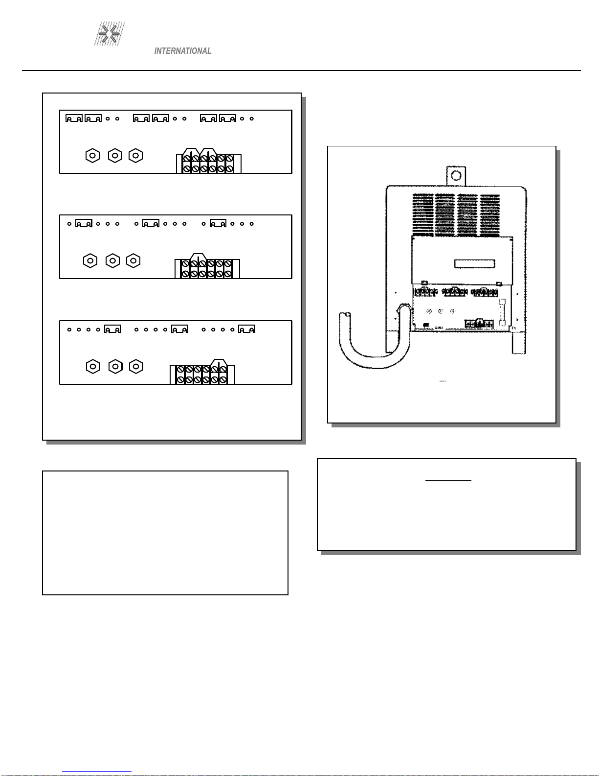
This unit is equipped with input voltage jumper links either
installed or in a bag on the jumper link board to allow oper
a-
tion from different line voltages. If installed, the jumper links
are positioned for the highest voltage stated on the nameplate
or on the input data label. In either case the jumper links should
always be checked to see if they are properly positioned for
the
voltage being used.
Open the access door located on the lower portion of the rear
panel to expose the jumper link board. I
f necessary, reposition
the jumper links to match the line voltage being used. (see Fi
g-
ure 6.1)
ARC 1850
PRO WELD
PRIMARY WIRE
DELAY TYPE FUSE
SIZE
-
AWG
GND
SIZE IN AMPS
230V
NO.1(2)
NO.2
200
460V
NO.4(6)
NO.6
100
575V
NO.4(6)
NO.6
9
0
Figure 1
Jumper Link Arrangement
230V
L3L2L1
654321
1 654321 65432654321
L3L2L1
654321
1 654321 65432654321
L3L2L1
654321
1 654321 65432654321
460V
575V
Jumper Link connections
CAUTION
The stud labeled GND is connected to the unit chassis and
is for grounding purposes only. Do not connect a wire
from th
e terminal labeled GND to one of the three
-
phase
line terminals as this may result in “hot” power unit cha
s-
PAGE 3
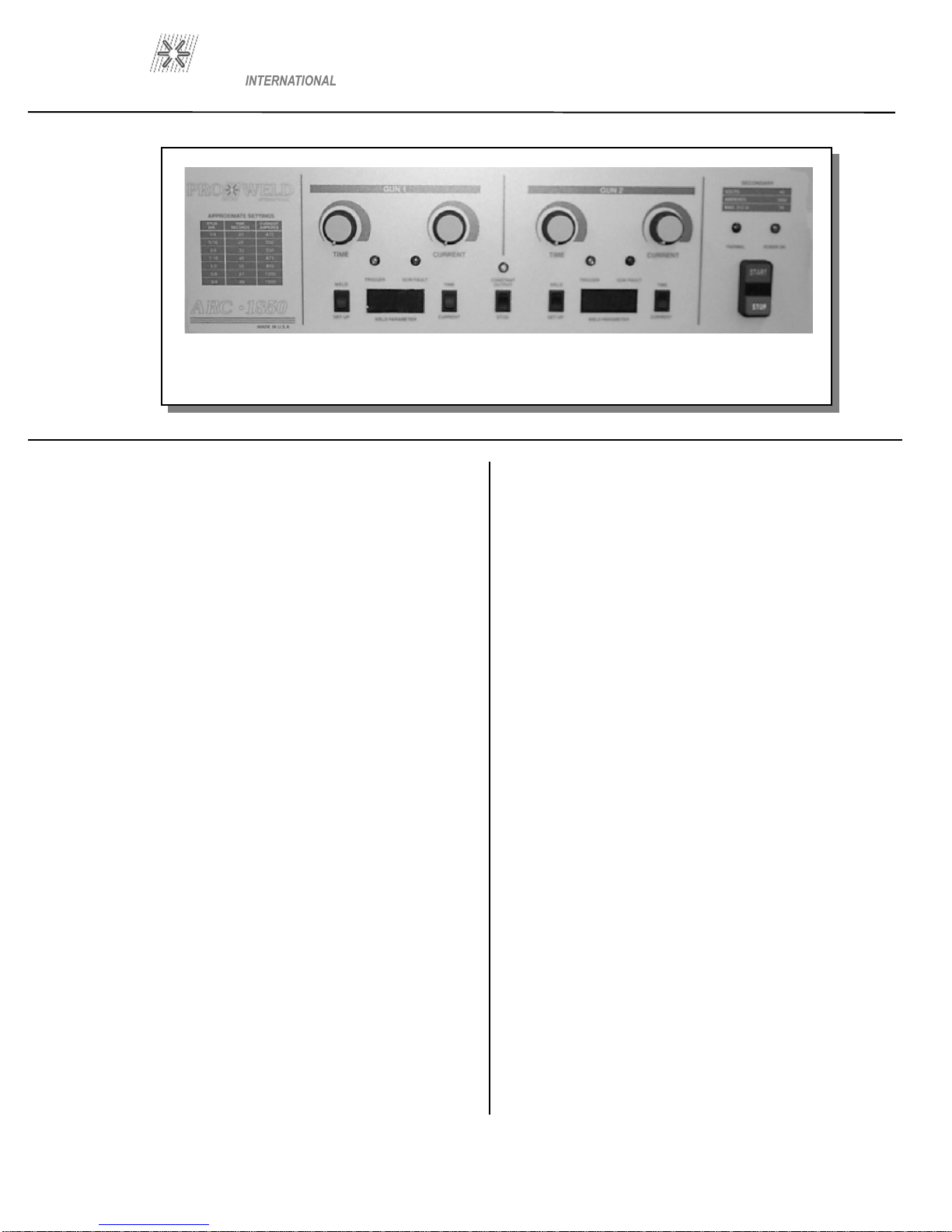
ARC 1850
PRO WELD
Figure 2 CONTROL PANEL FRONT
(DUAL GUN SYSTEM)
7
.0 CONTROL PANEL DESCRIPTION
START/STOP PUSH BUTTON
Momentarily depressing the START button will energize the
main contactor inside the unit allowing all circuits to be act
i-
vated and the the cooling fan to run. Momentarily depressing
the STOP button will deactivate the entire machine.
STUD/CONSTANT
OUTPUT SWITCH
When this switch is in the stud position, the unit is a ded
i-
cated stud welding power supply with built in time and cu
r-
rent controls. When in the constant output position the unit
becomes a welding power supply that can operate an external
control
box.
WELD/SETUP SWITCH
This switch directs the digital panel meter to display either
the setup parameters or the actual weld p
arameters. This
switch
must be in the weld position for the unit to weld.
TIME/CURRENT SWITCH
This switch selects either the
weld time or weld current that
is to be displayed on the digital meter.
WELD TIME ADJUSTMENT
Select: SETUP, TIME and adjust th
e time control knob until
the digital meter displays the desired time. Return setup
switch to WELD before attempting to weld. Th
e weld time is
adjustable from .1 to 1.6 seconds.
W
ELD/CURRENT ADJUSTMENT
Select: SETUP, CURRENT and adjust the current control
knob until the digital meter displays the desired current. R
e-
turn setup switch to WELD, before attempting to weld. Weld
current is adjustable from 100 to 1900 amps.
DIGITAL PANEL METERS
D
isplays weld time or weld current.
After a stud weld, the digital meter will automatically display
the actual weld parameters. The meter will automatically r
e-
set and display the time or current for each weld.
TRIGGER LED INDICATOR
The trigger LED “on” indicates a complete circuit to
the unit
through the gun control cables and gun switch. This LED
will turn “on” when the gun trigger is pressed.
GUN FAULT LED INDICATOR
The gun fault LED “on” indicates a shorted gun solenoid or a
shorted control cable. The LED will stay “on” and lock
out
the gun from triggering.
THERMAL LED INDICATOR
The thermal LED “on” indicates the internal temperature has
reached the max
imum rated temperature in either the weld
bridge or the main transformer. LED “on” will prevent the
gun from being triggered.
PAGE 4
ARC 1850
PRO WELD
8
.0 WELD GUN SET
-
UP
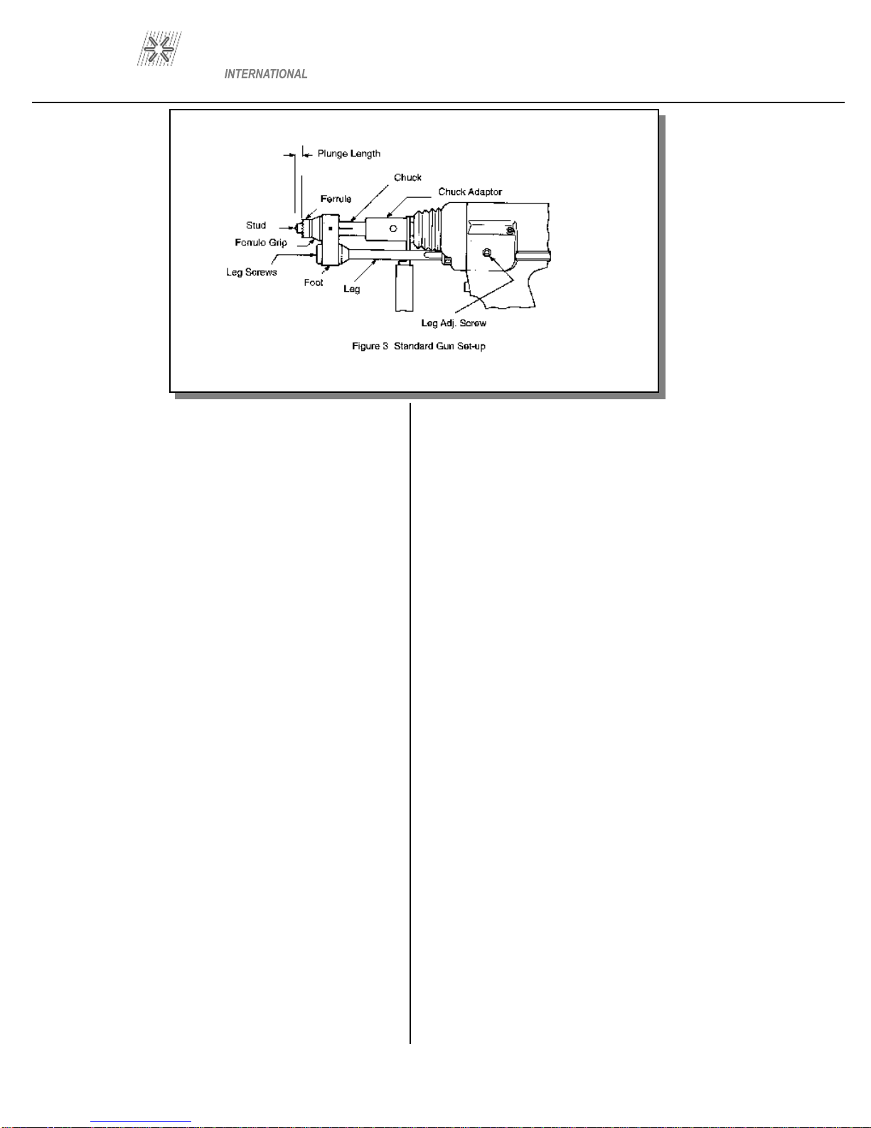
8.1 Plunge Length
1. A different and correctly sized chuck and ferrule grip are
needed for each different
stud diameter and style that will be
welded (see PRO WELD Accessories catalog for help in this
area). The appropriate chuck, or
stud holder, is inserted into
the tapered chuck adapter and tapped lightly to insure a tight
fit. The ferrule grip is inserted in the hole in the foot and s
e-
cured with the locking screws to hold it in place.
2. Studs must NOT bind or hang up on the foot, ferrule grip,
or ferrule duri
ng the entire stud welding process. To assure
this, the foot/ferrule arrangement must be centered in relation
to the stud to be
welded. To assure centering, loosen the leg
screws that hold the foot to the legs. Place a stud in the
chuck and a ferrule in th
e ferrule grip. With the leg screws
loosened, the foot will move freely in all directions. Adjust
the foot so that the stud is centered in the ferrule and no co
n-
tact occurs between the stud and the ferrule during retraction
or forward plunge of the stud.
3. The “plunge length” is the amount of the stud exposed b
e-
yond the ferrule during initial set
-
up. Set the plunge by loo
s-
ening the leg adjusting screws and moving the foot until the
stud extends 1/8” to 3/16” past the end of the ferrule. Tighten
the
leg adjusting screws after setting the plunge and recheck
centering to be sure the stud is aligned properly in the fe
r-
rule.
4. The lift height, which determines the arc length, has been
preset at the factory and will automatically lift and plung
e the
stud during the welding process. “Lift”, is the distance the
gun will raise the stud above the welding surface during the
weld. This distance governs the voltage and the arc. I
m-
proper lift will cause unsatisfactory welds. Refer to par
a-
graph 8
-
1 if it becomes necessary to a
d-
5
. Make sure that the cables are connected to the power
source (standard set
-
up is straight polarity
-
Negative to co
n-
troller (or gun) and Positive (ground cable) to the work su
r-
face).
6. Turn on the power supply and adjust the current and time
for the weld base diameter of the fastener to be welded.
7.
Place the gun, loaded with the stud and ferrule, squarely
against the grounded work surface. The main spring in the
gun will ta
ke up the “plunge length” and the ferrule will seat
against the base plate.
DO NOT MOVE THE GUN DURING THE WELD
CYCLE
8. Pull
the trigger holding the gun completely still as above.
The gun will lift the stud from the base plate and draw an
arc. The end
of the stud and the adjacent material of the base
plate, will be melted by the weld arc.
The gun will then
plunge the stud into the molten pool, exti
n-
guishing the arc, to end the controlled portion of the weld
cycle.
9. After the controlled weld cycle, allow the molten metal to
solidify briefly with the work surface to assure completion
of the cycle (about an extra second holding "still" after the
weld
is usually sufficient).
10. Remove the gun from the work by lifting straight away
from the welded stud (this will assure better
life to the gun's
expendable accessories). The ferrule may now be removed
by breaking it away from the welded stud to allow ins
pect
-
tion of the weld results. After inspection of sample welds the
gun can be adjusted, as per the step in this procedure,
for
optimum results.
PAGE 5

ARC 1850
PRO WELD
Figure 4
FUSE BLOCK
(Dual gun version shown)
F12
F11
F10
F9
F8
F7
F6
F5
F4
F3
F2
25 AMP
SLO BLO
5 AMP
CERAMIC
1 AMP
1 AMP
1 AMP
1 AMP
1 AMP
25 AMP
SLO BLO
25 AMP
SLO BLO
1 AMP
1 AMP
8
.2 Checking Gun Lift
To measure lift, turn the stud welding unit on and set the timer to
maximum time. (On certain units there
may be a Lift
Check switch available, and in these cases this switch can be used
to check lift.) Trigger the gun in the air, or
on a
non-
grounded or insulated surface, to observe the lift cycle. Mea
s-
ur
ing the distance the stud or gun mechanism
moves equals lift
-
usually this can be easily done by visual obse
r-
vation or simple measurement against a static ref-
erence point (i.e. the ferrule properly seated in the ferrule grip).
Recommen
ded Lift Settings.
Stud Base Dia.
Lift Setting
Less than 1/2”
1/16”
1/2” through 3/4”
3/32”
Greater than 3/4”
7/64”
When it does become necessary to adjust lift, you do so by r
e-
moving the rear cap from the gun. This will expose the
rear coil yoke assembly, the set screw and the lift adjusting screw
(Loos
en the set screw to avoid damaging the threads
of the lift adjusting screw).
To increase lift: turn the lift adjusting screw out (counter cloc
k-
wise).
To decrease lift: turn the lift adjusting screw in (clockwise).
Once the lift has been set, tighten the set screw and r
eplace the rear
cap.
PAGE 6

ARC 1850
PRO WELD
1
Figure 5 Control Unit (Front View)
9.0 PARTS LIST
ITEM
DESCRIPTION
PART NUMBER
1
Switch
104
-
0014
2
On/Off Operator
104
-
0016
2
N.O. Contact
104
-
0017
2
N.C.
Contact
104
-
0018
3
Power Light (Green Neon)
102-
0087
4
Knob
102
-
0060
4
20k Potentiometer
111
-
0012
5
Red LED
108
-
0028
6
Pan
el Meter
103
-
0004
7
Green LED
108
-
0029
8
Amber LED
108
-
0030
9
Positive Output Terminal
102
-
0058
10
4 Pole Panel Mounted Conn
ector
107
-
0001
9
10
11
1 6 7 5 2 3
4 8
PAGE 7
ARC 1850
PRO WELD
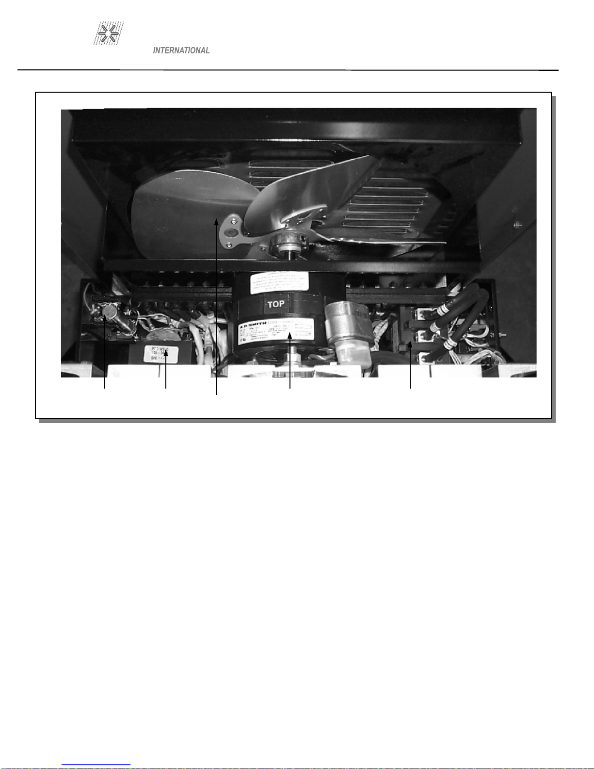
Figure 6 Control Unit
Rear
12
13
14
15
16
9.0 PARTS LIST
ITEM
DESCRIPTION
PART NUMBER
12
Fuse 6 amp 600 volt
102
-
0007
13
Control Transformer
105
-
0015
14
Fan Blade
14”
102
-
0083
15
Fan Motor
102
-
0085
16
Start Contactor
113
-
0017
PAGE 8

ARC 1850
PRO WELD
Figure 7 Control Unit
Side View
18
17
FRONT OF UNIT
9.0 PARTS LIST
ITEM
DESCRIPTION
PART NUMBER
17
Main Transformer
105
-
0023
18
Shunt
102
-
0107
PAGE 9
ARC 1850
PRO WELD
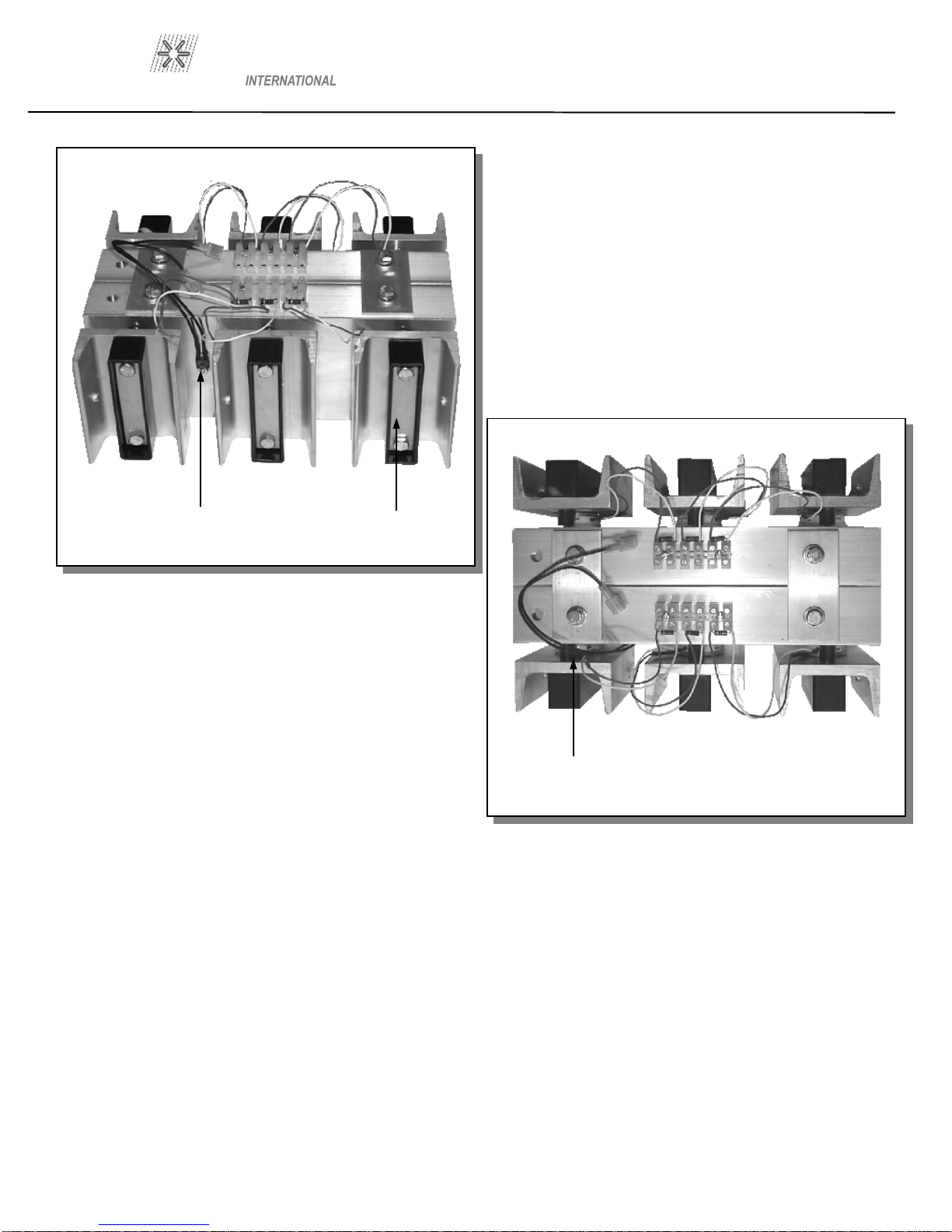
Figure 8
RECTIFIER, SCR ASSEMBLY
SIDE AND TOP VIEW
9.0 PARTS LIST
ITEM
DESCRIPTION
PART NUMBER
19
Weld SCR Thermostat
102
-
0032
20
Weld SCR Clamp
102
-
0109
21
Weld SCR
108
-
0058
19
20
21
PAGE 10

ARC 1850
PRO WELD
9.0 PARTS LIST
ITEM
DESCRIPTION
PART NUMBER
22
Choke Coil
105
-
0004
23
Time Control P.C.Board
600
-
0010
24
Current Control
P.C.Board
600
-
0012
25
Monitor Control P.C.Board
600
-
0011
26
Time Control P.C.Board
600
-
0010
27
Fuse Block
104
-
0015
28
Sustai
ning arc SCR
108
-
0042
29
Gun Discharge Capacitor
106
-
0024
Front of Unit
Figure 9
Printed Circuit Board Enclosure
Top and Side View
22
23
24
25
26
27
28
29
PAGE 11
ARC 1850
PRO WELD
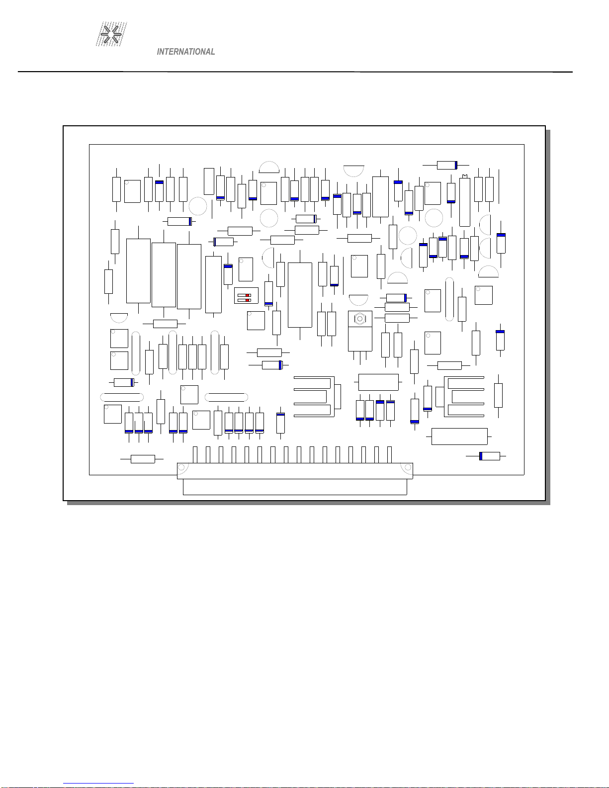
PAGE 12
Figure 10
GUN TIME CONTROL P.C. BOARD
P/N 600
-
0010
21
ON
OFF
IC104
V112
C104
+
+
R122
IC103
R121
D122
R123
R124
C106
C107
D118
R130
R128
D125
V106
D126
R144
R131
R132
D119
D116
R145
D103
R114
C102 +
D117
ZD102
R119
IC102
D114
R118
R112
R125
C105
V109
V110
D113
R117
D115
R116
D112
D104
V108
R115
+
R141
R142
OP101
V103
D102
R103
R155
V111
D111
D139
OP104
R126
R127
R153
D124
ZD105
D127
C108
+
R139
R138
C110 +
R104
C109 +
R129 R120
V105
R137
OP
109
OP
105
C111
R149
R143
C103
R136
R135
R150
R134
C112
D140
OP
102
R102
R101
R110
R109
R108
R140
C101
+
D101
D133
D132
D135
D134
D138
R151
Q101
D107
D108
D106
D105
ZD103
ZD104
V102
R107
D121
R113
R105
IC101
R146
D109
VR101
R111
R154
OP
103
OP110
C115
R147
D110
C114
OP
106
C113
OP
107
OP
108
R133
D131
D130
D129
D136
D137
R152
D120
V104
V107
ZD101
R148

ARC 1850
PRO WELD
Figure 11
MONITOR P.C. BOARD
P/N 600
-
0011
PAGE 13
IC201
R231
V201
R226
R202
C202
R203
D201
C201 +
R206
OP203
C209
+
IC203 R211
R212
R213
R210
IC202
R207
R208
R209
R204
OP201
OP202
C204
C203
R215
OP205
OP207
OP213 OP209
C205
OP204
C206
+
D204
V202
R217
R216
D202
D203
R218
D207
OP208
R221
R220
V204
V203
R219
R234
OP210
ZD202
D209
OP206
R223
D205
D206
R225
V205
R224
D207
C208
+
R227
V206
V207
OP212
OP211
C207
R222
R235
D210
ZD203
D208
R228
R229
R230
VR201
ZD201
R232
R233
R201
R205
R214
Table of contents
Other Pro-Weld Welding System manuals


Popular Welding System manuals by other brands

Telwin
Telwin 954374 instruction manual

Campbell Hausfeld
Campbell Hausfeld WF2010 Operating instructions & parts manual

Kemppi
Kemppi A5 MIG Rail System 2500 operating manual

Telwin
Telwin 954426 instruction manual

Magmaweld
Magmaweld Monotig 160ip user manual

MEGAPOWER
MEGAPOWER MP-13030HWG Operator's manual

GYS
GYS EASYMIG 110 manual

ESAB
ESAB Aristo Mig C3000i instruction manual

Lincoln Electric
Lincoln Electric AC-225 Technical specifications

Praxair
Praxair PROSTAR manual

Lincoln Electric
Lincoln Electric LINC FEED 37 Operator's manual

Chicago Electric
Chicago Electric 55167 Assembly and operating instructions


