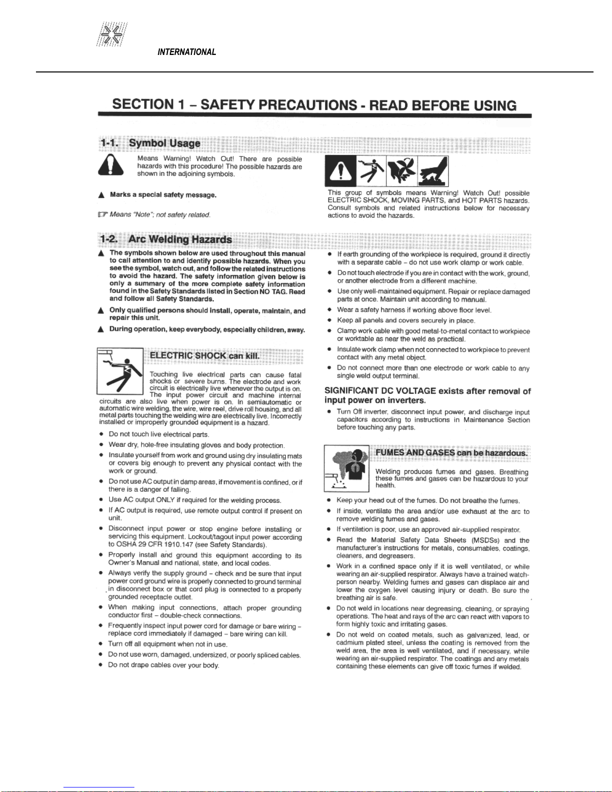
Pro-Weld AG-805 User manual

OPERATION/MAINTENANCE
MANUAL


300-0805
PRO WELD
TABLE OF CONTENTS
1.0 INTRODUCTION........................................................................................ 1
2.0 WARRANTY..........................................................................................…... 1
3.0
SUGGESTED SAFETY
PRECAUTION...................................................
1
4.0 GENERAL DESCRIPTION........................................................................ 2
5.0
UNPACKING................................................................................................
2
6.0
GUN SET
-UP................................................................................................. 3
7.0
WELD TEST AND INSPECTION.............................................................
5
7.1
WELD TEST.................................................................................................
5
7.2 WELD INSPECTION.................................................................................. 5
7.3
CAUSES OF POOR OR ERRATIC WELDS...............…...............…….
5
7.4
TROUBLE SHOOTING POOR WELDS..................................................
7
8.0
MAINTENANCE..........................................................................................
7
8.1
DISASSEMBLY..........................................................……………………..
7
8.2
RE
-
ASSEMBLY…………………………..............................................…..
7
8.3 WELD CABLE REPLACEMENT..……………....................................... 8
8.4 CONTROL CABLE REPLACEMENT..................................................… 8
8.5 GUN MAINTENANCE................................................................................. 8
PARTS LIST GUN ASSEMB
LY ARC STD. LD................…......………. 9,10
9.0 TROUBLE SHOOTING GUIDE............................................................... 11
PRO WELD 300-0805

300-0805
PRO WELD
PRO WELD 300-0805

300-0805
PRO WELD

PRO WELD 300-0805
1
.0 INTRODUCTION
Your new stud welding equipment is constructed
of the finest components and material available.
Used properly
, this equipment will give you years
of profitable, efficient service.
The system incorporates the latest in engineering
advanc
es, for complete reliable welding of mild
steel, stainless steel, and aluminum.
2.0 WARRANTY
The electrical and mechanical co
mponents of the
stud welder are thoroughly performance inspected prior
to assembly in the welder. The assembled welder is
completely performance checked. The welder is d
e
li
v-
ered to you in functional electro
-
mechanical cond
i
tion.
All parts used in the assembly of the welder and
its accessories are fully warranted for a period of 1
YEAR from the date of delivery. In addition, the wel
d-
ing capacitors are warranted for a period of 1 YEAR
from the date of delivery. The printed circuit boards
used in all proweld equipment are warranted for a p
e-
riod of 3 years.
Under the warranty, the manufacturer reserves
the right to repair or replace, at their option, defective
part
s which fail during the guarantee period. Notice of
any claim for warranty repair or replacement must be
furnished to the manufa
cturer by the purchaser within
ten (10) days after the defect is first discovered. The
manufacturer does not assume any liabilit
y for paying
shipping cost or any labor or materials furnished where
such cost are not expressly authorized in writing.
The ma
nufacturer does not warrant any parts or
accessories against failures resulting from misuse,
abuse, improper installation, malad
justment, or use not
in accordance with the operating instructions furnished
by the manufacturer. The warranty is valid only whe
n
studs are purchased from sources approved by the
manufacturer or are of identical specifications to the
manufacturer’s
3
.0 SUGGESTED SAFETY PRECAUTIONS
In any welding operation, it is the responsibility of the
welder to observe all safety rules to insure his or her pe
r-
sonal safety and to protect those working in the area.
Reference is directed, without endorsement or recomme
n-
dation, to ANSI Z49.1, Safety in Welding and Cutting, and
to AWG Publication A6
-
66, Recommended Safe Practices
for Gas
-Shielded
Arc Welding.
1. Always treat electricity with respect. Under open ci
r-
cuit conditions, the welding machines output voltage may
be dangerous.
2. Don’t work on live circuits or conductors. Disconne
ct
the main power before checking the machine or perfor
m-
ing any maintenance.
3. Be sure the welding machine cabinet is properly
grounded to a good electrical ground. Consult local ele
c-
tr
i
cal codes.
4. Never operate a welder in the rain, or operate a welder
while standing in water. Avoid wearing wet or sweaty
clothes when welding.
5. Don’t operate with worn or poorly connected cables,
and don’t operate the weld gun with loose cable conne
c-
tions. Inspect all cables frequently for insulation failures,
exposed wires, loose connections and repair as needed.
6. Don’t
overload welding cables or continue to operate
with over heated cables.
7. Don’t weld near flammable materials or liquids in
or
near the area, or on ducts or pipes carrying explosive
gases.
PAGE 1

300-0805
PRO WELD
8
. Don’t weld on containers which have held
combustible or flammable materials, or on m
a-
terials which give off flammable or toxic v
a-
pors when heated.
9. Be sure to provide for proper ventilation
when welding in a confined area.
10. Never look at the electr
ic arc without
wea
r
ing protective eye shields.
11. Always use the proper protective clothing,
gloves, etc.
12. Never strike an arc when near a
bystander
who is unaware of the danger of ultraviolet
light to their eyes.
4
.0 GENERAL DESCRIPTION
AG
-
805 LIGHT DUTY ARC GUN W/DAMPER
(Part No. 300
-
0805)
A shaped to the hand, semi automatic stud welding
tool. Welds any length stud with a diameter range of
12 gauge through 5/8 inches. Refer to figure 4
-
1 for
weight and size s
pecifications.
5.0 UNPACKING
There is very little to do when unpacking your ARC
Stud Welding gun. Your Stud Welder comes co
m-
plete with all the accessories and tool required for
set
-
up, adjustment, and maintenance. Aside from the
correct chuck, ferrule grip, and any special access
o-
ries required for your application your ARC weld
gun is ready for hook
-
up to a Pro Weld power
source.
PAGE 2
Typical working weight gun plus
4 feet of unsupported 1/0 cables ..7 pounds
Shipping weight of gun plus
approximately 8 fee
t of
1/0 cable and connectors....... 11 pounds
Note: Chuck and ferrule grip are not standard
and must be ordered separately.
Figure 4
-
1 Standard AG
-
805 M.D. ARC Gun
1.0
10
6.1
6.6

PRO WELD 300-0805
6
.0 GUN SET
-
UP
The standard gun set
-
up is used for welding the m
a-
jority of applications. It consists of the standard a
d-
justable face plate, two legs, a foot, chuck adapter,
chuck, and spring for your specific stud size.
The following is a step by
step explanation of the
co
r
rect way to set up the gun. (Refer to Figure 6
-
1)
1. A different, and correctly sized, chuck and ferrule
grip are needed for e
ach different stud diameter and
style that will be welded. The appropriate chuck, or
stud holder, is inserted into the tapered
chuck adapter
and tapped lightly to insure a tight fit. The ferrule
grip is inserted in the hole in the foot and secured
with the locking screws to hold it in place.
2. Studs must NOT bind or hang up on the foot, fe
r-
rule grip, or ferrule during the entire stud welding
process. To assure this, the foot/ferrule arrangement
must be centered in
relation to the stud to be welded.
To assure centering, loosen the locking screws that
hold the foot to the legs. Place a stud
in the chuck
and a ferrule in the grip. With the locking screw
loosened, the foot will move freely in all directions.
Adjust the foot so that the stud is centered in the fe
r-
rule and no contact occurs between the stud and the
ferrule during retraction or forward plunge of the stud.
Tighten the lockin
g screws after centering the stud.
3. The “Plunge Length” is the amount of stud exposed
beyond the ferrule during initial set
-
up. Set the plunge
by loosening the leg adjusting screws and moving the
foot until the stud extends 1/8” to 3/16” past the end
of
the ferrule. Tighten the leg adjusting screws after se
t-
ting the plunge and re
-
check centering to be sure the
stud is aligned properly in the ferrule.
4. The lift height, which deter
mines the arc length,
has been pre
-
set at the factory and will automatically
lift and plunge the stud during the welding process.
“Lift” is the distance the gun will raise the stud above
the welding surface during the weld. This distance
governs the volta
ge and the arc. Improper lift will
cause unsatisfactory welds.
To measure the lift, turn the stud welding unit on and
set the
timer to maximum time. (On certain units there
may be a Lift Check switch available, and in these
cases this switch can be used
to check lift.) Trigger
the gun in the air or on a non-
grounded or insulated
surface, to observe the lift cycle. Measuring the di
s-
tance the stud or gun mechanism moves equals lift.
Usually this can be easily done by visual observation
or simple measurement
against a static reference point
(i.e. the ferrule properly seated in the ferrule grip).
PAGE 3
Chuck Adaptor
Chuck
Locking Screws
Ferrule
Plunge Length
Stud
Ferrule Grip
(2) Foot
Screws
Foot
Leg
Leg Adj. Screw
Figure 6
-
1 GUN SET
-
UP
300-0805
PRO WELD
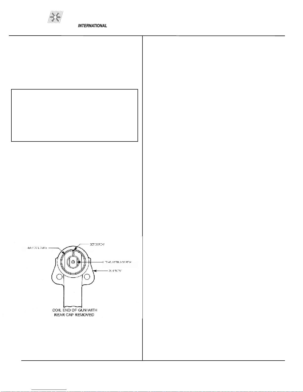
W
hen it does become necessary to adjust the lift,
you do so by removing the rear cap from the gun.
This will expose the rear coi
l choke assembly, the
set screw, and the lift adjusting screw (Refer to Fi
g-
ure 6
-
2).
Loosen the set screw.
To increase lift: turn the adjusting screw out
(counter clockwise).
To decrease lift: turn the lift adjusting screw in
(clockwise).
Once the lift has been set, tighten the set screw and
replace the rear cap.
Figure 6
-
2 LIFT ADJUSTMENT
RECOMMENDED LIFT SETTINGS
Stud Base Dia.
Lift Setting
Less than 1/2”
1/16”
1/2” through 3/4”
3/32”
Greater than 3/4”
7/64”
PAGE 4
5
. Make sure that the cables are connected to the
power source (standard set
-
up is straight polarity
–
Negative to controller, or gun, and Positive, ground c
a-
ble, to work surface).
6. Turn on the power supply and adjust the current and
time for the weld base diameter of the fastener
to be
welded.
7. Place the gun, loaded with the stud and ferrule,
squarely against the ground work surface. The main
spring i
n the gun will take up the “plunge length” and
the ferrule will seat against the base plate.
8. Pull the trigger holding the g
un completely still as
above. The gun will lift the stud from the base plate
and draw an arc. The end of the stud and the adja
cent
metal of the base plate will be melted by the weld arc.
The gun will then plunge the stud into the molten pool,
extinguish
ing the arc, to end the controlled portion of
the weld cycle
.DO NOT MOVE THE GUN DURING THE WELD
CYCLE.
9. After the contro
lled weld cycle, allow the molten
metal to solidify briefly with the work surface to assure
completion of the cycle (about an ex
tra second holding
“still” after the weld is usually sufficient).
10. Remove the gun from the work by lifting straight
away fr
om the welded stud (this will assure better life
to the gun’s expendable accessories). The ferrule may
now be removed by breaki
ng it away from the welded
stud to allow inspection of the weld results. After i
n-
spection of sample welds the gun can be adjusted, as
per the steps in this procedure, for optimum results

PRO WELD 300-0805
7
.0 WELD TEST AND INSPECTIONS
Testing of weld quality beyond visual inspection
varies with stud characteristics. Refer to AWS
(American Welding Society) Structure Welding
Code AWS D.1
-
Rev. 1
-
76. Welding procedures
are covered in Sections 4.28 and 4.29
. Weld test
and inspection is covered in Section 4.30, par
a-
graphs 1 through 4. (American Welding Society,
Inc., 2501 N.W. 7th, Street, Miami, Fla. 33125).
7.1 Weld Test
A. Bend Test
A bend test may be used to test weld results if the
stud may be destroyed. This is usually done with a
bending tool (a hollow
pipe with an inside diameter
just large enough to fit over the diameter of the
studs). The bend tool is placed over the stud, d
own
to the base material. The stud is then be repeatedly
bent away from its axis until failure occurs.
B. Torque Test
–
Threa
ded Studs
A torque test may be used on threaded studs. The
stud is twisted to the point of failure. A twisting
tensile load i
s applied by using a collar, washer and
nut. A bend test can be used on threaded studs as
well.
C. Test Results
In an accept
able weld, failure will occur in the stud
material or tear out of a thin base plate. Failure in
the weld requires adjustment of
procedure, weld
time and current setting.
7
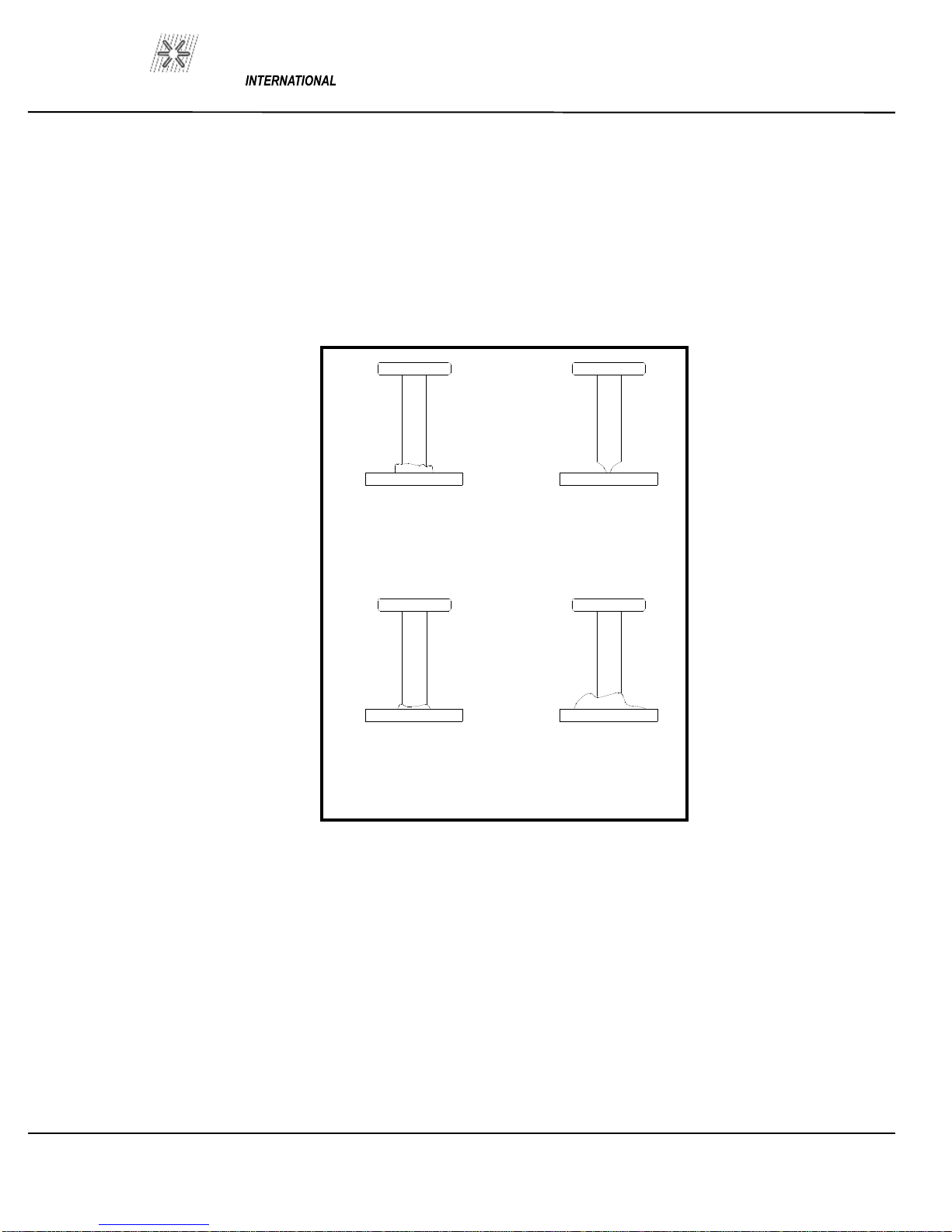
.2 Weld Inspection
Weld quality can be visually inspected. Refer to Fi
g-
ure 7
-
1 as a reference to the quality of the weld.
7.3 Causes Of Poor Or Erratic Welds
1. Loose chuck. Does not grip stud t
ightly.
(replace) Not enough engagement of stud to
chuck. (Adjust stop)
3. Poor surface condition of base mat
erial, excessive
oil, grease, rust, etc. (Clean)
4. Weld current or weld time setting too low or too
high. (Adjust to dia
meter of studs)
5. Broken or loose cables. (Repair)
6. Dirt in gun. (Clean)
7. Incorrect polarity. (Cables hooked
-up wro
ng)
8. Cables too closely coiled.
9. Arc blow is evidenced by “one side” welds. In
severe cases there will be no melt
ing under one
edge of flange while the opposite side is gouged
out or appears excessively hot. The principle
cause of arc bl
ow is a magnetic field induced by
the current flow during the weld. It occurs most
often on long, narrow strips of metal or n
ear
edges of sheets or plates. In some cases, a
change in grounding positions, or two ground on
the work piece, one at each
end or edge of work,
will correct the problem
PAGE 5
300-0805
PRO WELD
Figure 7
-
1 WELD INSPECTION
GOOD STUD WELD
A good full fillet
STUD HANG UP
Adjust foot to
insure the stud is
centered in the
ferrule
COLD WELD
Increase weld
current and/or
weld time
HOT WELD
Reduce weld
current and/or
weld time
PAGE 6

PRO WELD 300-0805
F
or assistance in sever cases, contact your local
sales representative.
10. Incorrect plunge setting. (Adjust to proper
settin
g)
11. Incorrect lift setting. (adjust to proper se
t-
ting)
12. Poor stud quality.
13. Arc shield so far off center from weld end
of stud that stud catches on edge of arc shield
and is not driven back into pool of molten
metal.
7.4 Trouble Shooting Poor Welds
1. Weld Too Hot
A) Decrease weld t
ime.
B) Decrease weld current.
C) Increase stud protrusion.
2.
Weld too Cold
A) Increase weld time.
B) Increase weld curre
nt.
C) Decrease stud protrusion
3. Arc Blow
A) Use double grounds.
B) Ground too close or not spaced evenly.
4. Hang
-
Up
A) Re
-align arc shield
8
.0 MAINTENANCE
(Refer to LD ARC GUN EXPLODED VIEW in Section 10
of this manual for location for “()” numbers noted in this
text.)
8.1 Disassembly of Gun
1. Loosen leg set screws (28), remove foot and leg asse
m-
bly. Unscrew chuck adaptor and remove bellows (2).
2. Unscrew end cap nuts (3) and remove front cover(4)
3. Disconnect weld ca
ble (31) from lifting rod assm (6) by
removing screw (8). Remove lifting rod assembly (6) and
main spring (7).
4. Slide out lift stop housing (10), lifting ring (11), mov
e-
able core (12), and core spring (13).
5. It is only necessary to remove rear cap (20) for adjusting
lift. It is not necessary t
o remove cap for normal cleaning of
gun.
6. To replace damper (33), unscrew plunge damper assemly
from front cap (4). The dampe
r will unscrew from the
damper cover (32).
8.2 Reassembly of Gun
1. Assemble lifting ring (11) with moveable core (12) and
core spring (13) into lift stop housing (10). Install into gun
body (14).
2. Install lifting rod assm (6) and main spring (7).
3. Connect weld cable (31) to lifting rod assembly (6) with
screw (8).
PAGE 7

300-0805
PRO WELD
3. Connect the
black
wire on the new cable (30) to
one terminal on the switch assembly (25).
4. Connect the
white wire to the ot
her terminal.
5. Connect
green
control cable wire to one of the
gun coil leads using wire nut.
6. Connect
red
control cable wi
re to the other gun
coil lead using a wire nut.
7. Re
-
install switch assembly and handle cover.
8.5 Gun Maintenance
If the g
un motion becomes sluggish or erratic the
gun should be disassembled, cleaned, and lubr
i-
cated.
A. Disassemble the gun as described. Blow or
wipe the gun body and parts clean.
B. The inside diameters of adjustabl
e core screw,
the lifting ring and mating diameters on the lifting
rod should be carefully examined for wear or rust.
Although the lubrication should prevent any oxid
a-
tion on these surfaces, if they reveal signs of dirt
or a dull reddish brown stain, clean and polish with
a fine abrasive paper,
grip #0 or finer.
C. Lubricate lifting rod surface with a thin coat of
high temperature bearing grease, Lubricate M
-24-
M or e
quivalent.
PAGE 8
4. Install front cap (4) end cap nuts (3), bellow (2),
and chuck adaptor (1). Make sure chuck adaptor is
securely tightened.
5.
Guns with plunge damper, replacement damper
(33) has to be screwed all the way into the damper
cover (32). Screw damper assembl
y into front cap
(4)
6. Install foot and leg assembly. Adjust the plunge
and lift.
7. Replace rear cap (20) and secure with sc
rew
(21).
8.3 Weld Cable Replacement
1. Disassemble gun as indicated in disassembly of
gun through step 4.
2. Remove handle
cover screws (26) lift off handle
cover (27).
3. Pull weld cable (31) out of gun body (14).
4. Place new weld cable into gun b
ody handle and
through cable hole in gun body.
5. Secure weld cable with screw (8) to lifting rod
assembly (6). Tighten securel
y.
6. Install handle cover and reassemble gun.
8.4 Control Cable Replacement
1. Remove handle cover screws (26) lift off hand
le
cover (27).
2. Remove wire nuts from the two wires going to
the gun coil (16). Disconnect the two wires from
the switch asse
mbly (25) and remove control cable
(30).

PRO WELD 300-0805
PAGE 9
ITEM
DESCRIPTION
PART NO.
1
CHUCK ADAPTOR
033
-
505
2
CONNECTOR STUD
033
-
506
3
BELLOWS
302
-
0018
4
SHAFT EXT.
302
-
0036
5
FRONT CAP
302
-
0003
6
NYLON BEARING.
033
-
491
7
LIFTING ROD
302
-
0012
8
SPRING
,MAIN
302
-
0017
9
DAMPER COVER
302
-
0011
10
DA
MPER
302
-
0007
11
NUT, END CAP
033
-
481
12
DAMPER STOP
302
-
0021
13
SCREW, #8
-
32 X 3/8 FSCS
115
-
0011
14
LIFT HOUSING
301
-
00
19
15
LIFTING RING
301
-
0014
16
MOVEABLE CORE
301
-
0013
17
SPRING
, CORE
301
-
0012
18
GUN BODY
302
-
0001
19
COIL YOKE BEARIN
G
301
-
0009
ITEM
DESCRIPTION
PART NO.
21
WAVE WASHER
102
-
0117
22
REAR COIL YOKE
301
-
0016
23
SCREW, #8
-
32 X 1/4 SET
115
-
0010
24
LIFT ADJ
. SCREW
301
-
0008
25
REAR CAP
033
-
493
26
SCREW, #8
-
32 X 3/4 PAN HD.
037
-
521
27
HANDLE COVER
302
-
0009HD
28
SCREW, #10
-
32 X 1/2
OVAL HD
115
-
0009
29
SCREW, 5/16
-
18 X 3/8 SET
037
-
557
30
SPRING, TRIGGER
302
-
0016
31
SNAP RING
302
-
0023
32
TRIGGER BUTTON
30
2-
0013
33
TRIGGER SWITCH ASSY
302
-
0010
34
CABLE GUIDE ASSY
302
-
0024
34A
SCREW, #10
-
32 X .625 SHCS
115
-
0012
34B
CLAMP, CABLE
GUIDE
302
-
0024
-2
34C
SUPPORT, CABLE GUIDE
302
-
0024
-1
35
CONTROL CABLE ASSY
302
-
0028
36
WELD CABLE ASSY
036
-
904
WELD CABLE B
OOT
036
-
904
-1
37
CONTROL CABLE BOOT
036
-
897

300-0805
PRO WELD
S
ection 9.0
TROUBLE SHOOTING GUIDE
CAUTION:
Turn off the power when trouble shooting the control. Welding voltage can cause el
ectric shock and
burns.
Trouble shooting should be done by qualified personnel trained to work on this type of equi
p-
ment.
PROBLEM
POSSIBLE CAUSE
REMEDY
Control unit cycles but gun
Broken or loose control cable
Check all wires for conti
nuity
does not lift.
wires.
and repair.
Dirt in gun.
Disassembly and clean.
Misalignment of accessories
Re
-
align fastener in center of
i.e. legs, foot piece, grip)
by loosening the screws
holding the foot and the legs.
Lift incorrectly
set.
Adjust lift to recommend
settings (See section “Set
-up
of Weld Gun” for suggested
settings.)
Weld quality
appears
Faulty or loose ground
Clean area for grounding.
inconsistent from one
connection.
Repair or tighten clamp.
weld to
the next.
Poor surface condition,
Clean area at each weld.
excessive oil, grease,
rust etc.
Incorrect plunge setting.
Be sure plunge is adequate
for fastener being welded.
(See section “Set
-up
of Weld Gun” for suggested
setting
s.)
PAGE 10

PRO WELD 300-0805
TROUBLE SHOOTING GUIDE (continued)
CAUTION:
Turn off the power when trouble shooting the control. Welding voltage can cause e
lectric shock and
burns.
Trouble shooting should be done by qualified personnel trained to work on this type of equi
p-
ment.
PROBLEM
POSSIBLE CAUSE
REMEDY
Weld quality (continued)
Poor quality fasteners.
Loose chuck
Rep
lace chuck.
Gun lifts but fastener
Loose chuck.
Replace chuck.
Does not pull away from
The work plate.
Accessory misali
gnment.
See previous problem for
re
-
alignment suggestions.
PAGE 11

300-0805
PRO WELD

WELD
PRO
MANUFACTURED BY
MADE IN THE U.S.A.
Table of contents
Other Pro-Weld Welding System manuals


Popular Welding System manuals by other brands


ESAB
ESAB Aristotig 255 LTN 255 instruction manual

Kemppi
Kemppi FASTMIG MS 200 operating manual

Saf-Fro
Saf-Fro DIGIWAVE III Series Instruction for operation and maintenance

Sealey
Sealey POWERMIG2500 instructions

Lincoln Electric
Lincoln Electric SF7000 Operator's manual

Expondo
Expondo MSW S-SPOTTER 4000 user manual