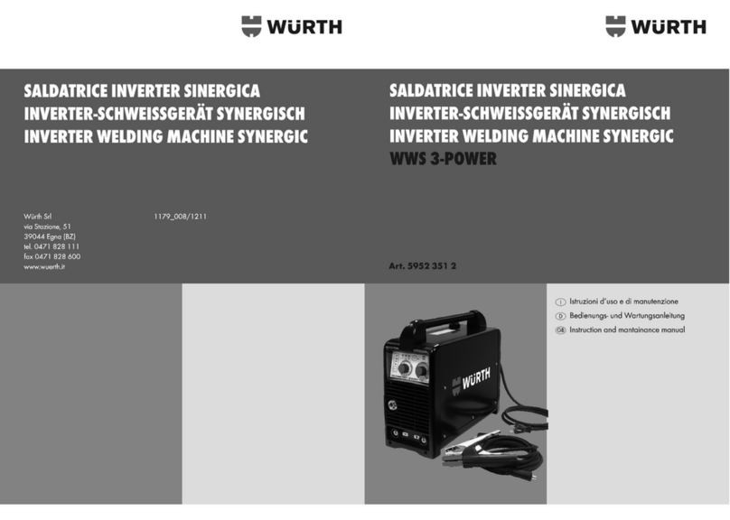
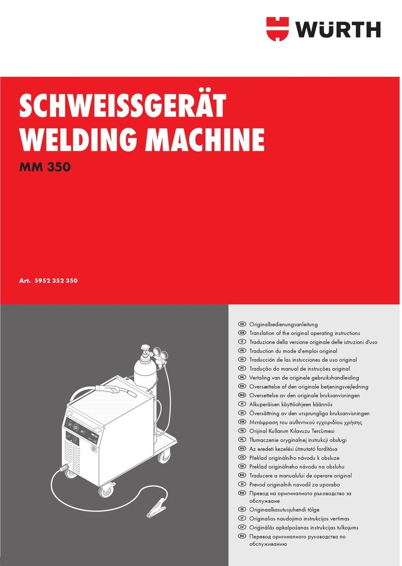
wurth MM 230 User manual

SCHWEISSGERÄT
WELDING MACHINE
MM 230
Art. 0702 352 0
Originalbetriebsanleitung
Translation of the original operating instructions
Traduzione delle istruzioni di funzionamento originali
Traduction des instructions de service d’origine
Traducción del manual de instrucciones de servicio
original
Tradução do original do manual de funcionamento
Vertaling van de originele gebruiksaanwijzing
Oversættelse af den originale betjeningsvejledning
Original driftsinstruks i oversettelse
Alkuperäiskäyttöohjeen käännös
Översättning av bruksanvisningens original
Μετάφραση της γνήσιας οδηγίας λειτουργίας
Orijinal işletim kılavuzunun çevirisi
Tłumaczenie oryginalnej instrukcji eksploatacji
Az eredeti üzemeltetési útmutató fordítása
Překlad originálního návodu k obsluze
Preklad originálneho návodu na obsluhu
Traducerea instrucţiunilor de exploatare originale
Prevod originalnega Navodila za uporabo
Превод на оригиналното ръководство за
експлоатация
Originaalkasutusjuhendi koopia
Originalo naudojimosi instrukcijos vertimas
Ekspluatācijas instrukcijas oriģināla kopija
Перевод оригинала руководства по эксплуатации
5
3
4
1
2
1
2
5
4
t
0
2
46
8
10
3
Ø18 Ø18 Ø18
Originalbedienungsanleitung
Translation of the original operating instructions
Traduzione della versione originale delle istruzioni d'uso
Traduction du mode d'emploi original
Traducción de las instucciones de uso original
Tradução do manual de instruções original
Vertaling van de originele gebruikshandleiding
Оversættelse af den originale betjeningsvejledning
Oversettelse av den originale bruksanvisningen
Alkuperäisen käyttöohjeen käännös
Översättning av den ursprungliga bruksanvisningen
Μετάφραση του αυθεντικού εγχειριδίου χρήσης
Orijinal Kullanım Kılavuzu Tercümesi
Tłumaczenie oryginalnej instrukcji obsługi
Az eredeti kezelési útmutató fordítása
Překlad originálního návodu k obsluze
Preklad originálneho návodu na obsluhu
Traducere a manualului de operare original
Prevod originalnih navodil za uporabo
Превод на оригиналното ръководство за
обслужване
Originaalkasutusjuhendi tõlge
Originalios naudojimo instrukcijos vertimas
Oriģinālās apkalpošanas instrukcijas tulkojums
Перевод оригиналного руководства по
обслуживанию

2
DE ........................ 5 – 10
GB ........................ 11 – 16
IT ........................ 17 – 22
FR ........................ 23 – 28
ES ........................ 29 – 34
PT ........................ 35 – 40
NL ........................ 41 – 46
DK ........................ 47 – 52
NO ........................ 53 – 58
FI ........................ 59 – 64
SE ........................ 65 – 70
GR ........................ 71 – 76
TR ........................ 77 – 82
PL ........................ 83 – 88
HU ........................ 89 – 94
CZ ........................ 95 – 100
SK ........................ 101 – 106
RO ........................ 107– 112
SI ........................ 113– 118
BG ........................ 119– 124
EE ........................ 125– 130
LT ........................ 131– 136
LV ........................ 137– 142
RU ........................ 143– 148

I
10
10
11
17
4
3
18
1 2
19
5
9
8
7
6
121314
15
16
3

45
3
1
2
II
IV
V VI
1
2
0
5
6
3
4
7
1
p p p
richtig An-
pressdruck
zu hoch
falsche
Drahtvor-
schubrolle
III
26
2729
22
13
20
243313 30 31 32
36 3837 39
0
1
40 41
34
35
MV
2
3
4
5
6
2
3
4
5
6
10
10
Schweißdraht:SG-2 Ø 1,0m m
Stufe
1-1
1-2
1-3
1-4
1-5
1-6
1-7
1-8
1-9
1-10
1-11
1-12
2-1
2-2
2-3
2-4
2-5
2-6
2-7
2-8
2-10
2-11
2-12
MM350
SchweißstromMat.stärke
2-9
26
28
21
23
25
24
4

5
Hinweis
Es ist verboten, Veränderungen am
Gerät durchzuführen. Solche Änderun-
gen können zu Personenschäden und
Fehlfunktionen führen.
■Reparaturen am Gerät dürfen nur von hierzu
beauftragten und geschulten Personen durch-
geführt werden. Hierbei stets die Originaler-
satzteile der Adolf Würth GmbH & Co. KG
verwenden. Damit wird sichergestellt, dass die
Sicherheit des Gerätes erhalten bleibt.
■Vor Schweißbeginn Lösungsmittel, Entfettungs-
mittel und andere brennbare Materialien aus
dem Arbeitsbereich entfernen. Nicht bewegliche
brennbare Materialien abdecken.
Schweißen Sie nur, wenn die Umgebungsluft
keine hohen Konzentrationen von Staub,
Säuredämpfen, Gasen oder entzündlichen
Substanzen enthält. Besondere Vorsicht ist
geboten bei Reparaturarbeiten an Rohrsystemen
und Behältern, die brennbare Flüssigkeiten oder
Gase beinhalten oder beinhaltet haben.
■Gerät nicht dem Regen aussetzen, nicht ab-
spritzen und nicht dampfstrahlen.
■Schweißen Sie nie ohne Schweißschild. Warnen
Sie Personen in ihrer Umgebung vor den Lichtbo-
genstrahlen.
■Geeignete Absaugvorrichtung für Gase und
Schneiddämpfe verwenden. Verwenden Sie ein
Atemgerät, falls die Gefahr besteht, Schweiß-
oder Schneiddämpfe einzuatmen.
■Wird bei der Arbeit das Netzkabel beschädigt
oder durchtrennt, Kabel nicht berühren sondern
sofort den Netzstecker ziehen. Gerät niemals
mit beschädigtem Kabel benutzen.
■Plazieren Sie einen Feuerlöscher in ihrer Reichweite.
■Führen Sie nach Beendigung der Schweißar-
beiten eine Brandkontrolle durch (siehe UVV).
■Versuchen Sie niemals, den Druckminderer zu
zerlegen. Defekten Druckminderer ersetzen.
■Auf guten und direkten Kontakt der Werkstück-
leitung in unmittelbarer Nähe der Schweißstelle
achten. Den Schweißstrom nicht über Ketten,
Kugellager, Stahlseile, Schutzleiter etc. führen,
da diese dabei durchschmelzen können.
■Sichern Sie sich und das Gerät bei Arbeiten an
hochgelegenen bzw. geneigten Arbeitsächen.
■Das Gerät darf nur an ein ordnungsgemäß
geerdetes Stromnetz angeschlossen werden.
(Dreiphasen- Vier-Draht-System mit geerdetem
Neutralleiter oder Einphasen-Drei-Draht-System
mit geerdetem Neutralleiter). Steckdose und Ver-
längerungskabel müssen einen funktionsfähigen
Schutzleiter besitzen.
■Schutzkleidung, Lederhandschuhe und Leder-
schürze tragen.
■Tauen Sie keine eingefrorenen Rohre oder Lei-
tungen mit Hilfe eines Schweißgerätes auf.
■In geschlossenen Behältern, unter beengten Ein-
satzbedingungen und bei erhöhter elektrischer
Gefährdung dürfen nur Geräte mit
S
-Zeichen
verwendet werden.
■Schalten Sie das Gerät in Arbeitspausen aus
und schließen Sie das Flaschenventil.
■Sichern Sie die Gasasche mit der Sicherungs-
kette gegen umfallen.
■Zum Transport die Gasasche abnehmen.
■Ziehen Sie den Netzstecker aus der Steckdose,
bevor Sie den Aufstellungsort ändern oder
Arbeiten am Gerät vornehmen.
■Zur Kennzeichnung des Gerätes nicht in das
Gehäuse bohren oder Nieten anbringen.
Verwenden Sie Klebeschilder.
■Nur Original Würth Zubehör und
Ersatzteile verwenden.
Zu Ihrer Sicherheit
DE
Lesen Sie vor der ersten Benutzung
Ihres Gerätes diese Betriebsanleitung
und handeln Sie danach.
Bewahren Sie diese Betriebsanlei-
tung für späteren Gebrauch oder für
Nachbesitzer auf.
WARNUNG - Vor erster Inbetrieb-
nahme Sicherheitshinweise
unbedingt lesen!
Bei Nichtbeachtung der Betriebsanlei-
tung und der Sicherheitshinweise können Schäden
am Gerät und Gefahren für den Bediener und
andere Personen entstehen.
Bei Transportschaden sofort Händler informieren.
Sicherheitshinweise

6
Bestimmungsgemäße
Verwendung
Das Gerät ist bestimmt zum Schweißen von Stahl,
Aluminium und Legierungen, sowohl bei gewerbli-
chen als auch industriellen Einsatzbedingungen.
Für Schäden bei nicht bestimmungsgemä-
ßer Verwendung haftet der Benutzer.
Geräteschutz
Das Gerät ist elektronisch vor Überlastung geschützt.
Den Stufenschalter jedoch nicht unter Last betätigen.
Schließen Sie die Seitendeckel vor dem Schweißen.
Werkstück vor dem Schweißen mittels der Werk-
stückleitung mit dem Gerät verbinden.
Schweißspritzer von der Innenwand der Gasdüse
mit einer geeigneten Spezialzange entfernen.
Sprühen Sie die Innenwand der Gasdüse mit einem
Trennmittel ein oder verwenden Sie hierzu Düsen-
schutzpaste. Dies verhindert das Festbrennen von
Schweißspritzern. Sprühen Sie schräg, um ein Zuset-
zen der Schutzgasaustrittsbohrungen zu vermeiden.
Bei Verladung das Gerät nur an den dafür vorge-
sehenen Handgri anheben. Heben Sie das Gerät
nicht mittels eines Gabelstaplers oder ähnlichem am
Gehäuse an.
Geräteelemente
Schweissgerät (Abb. I)
1 Brenner
2 Sicherungskette
3 Schutzgasasche*
4 Gasaschenventil*
5 Inhaltsmanometer
6 Durchussmesser
7 Druckminderer
8 Schutzgasschlauch
9 Einstellschraube
10 Transportrollen
11 Seitenteil
12 Massezange
13 Zentralbuchse
14 Zentralstecker
15 Werkstückleitung
16 Masseanschluss
17 Bedienelemente
18 Handgri
19 Ablageäche
*nicht im Lieferumfang enthalten
4-Rollen-Vorschub (Abb. II)
20 Schwenkarm
21 Drahteinlauftaster
22 Kipphebel
23 Einlaufdüse
24 Drahtvorschubrolle
25 Regulierschraube
Drahtablaufdorn (Abb. II)
26 Mitnehmerdorn
27 Ablaufdorn
28 Drahtbremse
29 Haltemutter
Umrüstung der Drahtelektrode (Abb. IV)
30 Haltenippel (=Klemmteil) der PTFE- bzw. Kunst-
stoseele für 4,0 mm und 4,7 mm Außendurch-
messer
31 O-Ring 3,5 x 1,5 mm um den Gasaustritt zu
verhindern
32 Überwurfmutter
33 PTFE- und Kunststoseele
34 Stützrohr für PTFE- und Kunststoseele mit 4 mm
Außendurchmesser ersetzt das Kapillar-Rohr aus
Stahl im Zentralanschluss. Bei 4,7 mm Außen-
durchmesser entfällt das Rohr.
Bedienelemente (Abb. V/VI)
35 Temperaturkontrollanzeige
36 Netzkontrollanzeige
37 Drehregler für die Punktschweissdauer
38 Drehregler für den Drahtvorschub
39 Betriebswahlschalter
40 Hauptschalter
41 Stufenschalter
BGV-Prüfung
Der Betreiber von gewerblich genutzten Schweißan-
lagen ist dazu verpichtet, einsatzbedingt regelmä-
ßig eine Sicherheitsüberprüfung der Anlagen nach
EN 60974-4 durchführen zu lassen. Würth emp-
ehlt eine Prürist von 12 Monaten.
Auch nach Änderung oder Instandsetzung der
Anlage muss eine Sicherheitsüberprüfung durch-
geführt werden. Unsachgemäß durchgeführte
BGV-Prüfungen können zur Zerstörung der Anlage
führen. Nähere Informationen über BGV-Prüfungen
an Schweißanlagen erhalten Sie bei autorisierten
Würth Service-Stützpunkten.

7
Geräuschemission
Der Geräuschpegel des Geräts ist kleiner
als 70 dB(A), gemessen bei Normlast nach
EN 60974-1 im maximalen Arbeitspunkt.
Elektromagnetische
Verträglichkeit (EMV)
Dieses Produkt entspricht den derzeit geltenden
EMV-Normen.
Beachten Sie folgendes:
■Schweißgeräte können auf Grund ihrer hohen
Stromaufnahme Störungen im öentlichen
Stromnetz verursachen. Daher unterliegt der
Netzanschluss Anforderungen in Bezug auf die
maximal zulässige Netzimpedanz. Die maximal
zulässige Netzimpedanz (Zmax) der Schnittstelle
zum Stromnetz (Netzanschluss) wird in den
technischen Daten angegeben. Halten Sie ggf.
Rücksprache mit dem Netzbetreiber.
■Das Gerät ist bestimmt zum Schweißen bei
gewerblichen als auch industriellen Einsatzbe-
dingungen (CISPR 11 class A). Bei Einsatz in
anderen Umgebungen (z. B. Wohngebieten)
können andere elektrische Geräte gestört
werden.
■Elektromagnetische Probleme bei der Inbetrieb-
nahme können entstehen in:
• Netzzuleitungen, Steuerleitungen, Signal- und
Telekommunikationsleitungen in der Nähe der
Schweiß- bzw. Schneideinrichtung
• Fernseh- und Rundfunksender und -empfänger
• Computer und anderen Steuereinrichtungen
• Schutzvorrichtungen in gewerblichen Einrich-
tungen (z. B. Alarmanlagen)
• Herzschrittmachern und Hörhilfen
• Einrichtungen zum Kalibrieren oder Messen
• in Geräten mit zu geringer Störfestigkeit
Falls andere Einrichtungen in der Umgebung gestört
werden, können zusätzliche Abschirmungen notwen-
dig werden.
■Die zu betrachtende Umgebung kann sich bis
über die Grundstücksgrenze erstrecken. Dies ist
von der Bauart des Gebäudes und anderen dort
stattndenden Tätigkeiten abhängig.
Betreiben Sie das Gerät nach den Angaben und
Anweisungen des Herstellers. Der Betreiber des
Geräts ist für die Installation und den Betrieb des
Geräts verantwortlich. Treten elektromagnetische
Störungen auf, ist der Betreiber (evtl. mit techni-
scher Hilfe des Herstellers) für deren Beseitigung
verantwortlich.
Technische Daten
Art. 0702 352 0
Schweißbereich 30 - 230 A/
15,5 - 25,5 V
Leerlaufspannung 16,8 - 32,6 V
Spannungseinstellung 7 Stufen
ED 100 %, 40 °C 115 A
ED 20 %, 40 °C 230 A
schweißbare Drähte, Stahl 0,6 - 1,0 mm Ø
schweißbare Drähte, Alu 1,0 - 1,2 mm Ø
Drahtfördergeschwindigkeit 1 - 23 m/min
Netzspannung 400 V/3~
Netzfrequenz 50/60 Hz
Netzabsicherung 16 A tr/C
max. Netzstromaufnahme 9,8 A
max. Aufnahmeleistung 6,8 kVA
Leistungsfaktor 0,89 cos φ
Kühlart F
Isolierstoklasse F
Schutzart (IEC 529) IP 23
Brennertyp ML 2500
Maße (L x B x H) 830 x 390 x 690 mm
Gewicht 66 kg
Schutzklasse / I

8
Vor der Inbetriebnahme (Abb. I)
Brenneranschluss
1. Schließen Sie den Zentralstecker [14] des Bren-
ners [1] an den Zentralbuchse [13] an.
Anschließen der Werkstückleitung
1. Schließen Sie die Werkstückleitung [15] an den
Masseanschluss [16] an.
2. Sichern Sie die Werkstückleitung [15] einer
Rechtsdrehung.
3. Befestigen Sie die Massezange [12] am
Schweißtisch bzw. Werkstück gut leitend.
Befestigen der Massezange
■Befestigen Sie die Massezange [12] in unmit-
telbarer Nähe der Schweißstelle. Achten Sie auf
eine feste, gut leitende Verbindung zwischen
Massezange und Werkstück.
Legen Sie die Massezange nicht auf
die Schweißanlage bzw. Gasasche,
da sonst der Schweißstrom über die
Schutzleiterverbindungen geführt wird
und diese zerstören kann.
Anschließen ans Stromnetz
Stecken Sie den Stecker in eine
geeignete Steckdose. Die Absicherung
muss den technischen Daten entspre-
chen.
Einlegen der Schweißdrahtspule (Abb. II)
1. Nehmen Sie das Seitenteil [11] ab und lösen Sie
die Haltemutter [29] am Ablaufdorn [27].
2. Stecken Sie die Schweißdrahtspule auf den
Ablaufdorn [27]. Achten Sie darauf, dass der
Mitnehmerdorn [26] einrastet. Verwenden Sie
für kleine Schweißdrahtspulen einen Adapter.
3. Stellen Sie die Drahtbremse [28] so ein, dass
beim Loslassen der Brennertaste die Schweiß-
drahtspule nicht mehr nachläuft.
Einfädeln der Drahtelektrode (Abb. II)
1. Schrauben Sie die Stromdüse des Brenners [1]
heraus.
2. Önen Sie das Seitenteil [11].
3. Klappen Sie die Kipphebel [22] zur Seite und
den Schwenkarm nach oben
1
2
.
4. Fädeln Sie die Drahtelektrode durch die Einlaufdü-
se [23] und die Zentralbuchse [13]
3
.
5. Klappen Sie den Schwenkarm [20] zurück und
arretieren Sie mit den Kipphebeln [22]
4
.
6. Schalten Sie das Gerät am Hauptschalter [40] ein.
7. Strecken Sie den Brennerschlauch.
8. Drücken Sie den Drahteinlauftaster [21].
9. Stellen Sie den Anpressdruck mit den Regulier-
schrauben [25] so ein, dass die Drahtvorschubrol-
len [24] beim Festhalten der Schweißdrahtspule
gerade noch durchdrehen.
Der Draht darf nicht geklemmt oder
verformt werden.
10. Drücken Sie den Drahteinlauf-
taster [21] solange, bis der Draht am Brenner-
hals ca. 20 mm herausragt.
11. Schrauben Sie die zur Drahtdicke passende
Stromdüse in den Brenner [1] und schneiden Sie
das überstehende Drahtende ab.
Anschließen der Schutzgasflasche
1. Stellen Sie die Schutzgasasche [3] auf die
Abstellplatte und sichern Sie diese mit der Siche-
rungskette [2].
2. Önen Sie das Gasaschenventil [4] mehrmals
kurz, um eventuell vorhandene Schmutzpartikel
herauszublasen.
3. Schließen Sie den Druckminderer [7] an die
Schutzgasasche [3] an.
4. Schrauben Sie den Schutzgasschlauch [8] am
Druckminderer [7] an.
5. Önen Sie das Gasaschenventil [4].
3Stellen Sie die Gasmenge bei gedrückter
Brennertaste an der Einstellschraube [9] des
Druckminderers [7] ein. Die Gasmenge wird am
Durchussmesser [6] angezeigt.
Gasmenge=Drahtdurchmesser x 10 l/min.
3Der Flascheninhalt wird am Inhaltsmanome-
ter [5] angezeigt.

9
Umrüsten der Anlage zum Schweißen
mit Aludraht (Abb. IV)
1. Wechseln Sie die Drahtvorschubrolle [24] gegen
eine passende Aluminium-Drahtvorschubrolle.
2. Tauschen Sie den Stahlbrenner gegen einen Alu-
Brenner, bzw. wechseln Sie die Stahlinnenspirale
gegen eine Kunststoseele [33].
3. Entfernen Sie das Stützrohr [34] in der Zentral-
buchse [13].
4. Kürzen Sie die überstehende Kunststosee-
le [33] so, dass sie ganz dicht an die Drahtvor-
schubrolle reicht und schieben Sie das entspre-
chend gekürzte Messingrohr zur Stabilisierung
über die überstehende Kunststoseele [33].
5. Ziehen Sie den Brenner fest und fädeln Sie die
Drahtelektrode ein. Die Bestellnummern der
Austauschteile sind vom eingesetzten Brennertyp
und Drahtdurchmesser abhängig und aus den
Brennerersatzteillisten ersichtlich.
Inbetriebnahme (Abb. VI / VII)
Die Bedienung der MM230 ist sehr einfach
konzipiert:
Der Drahtvorschub richtet sich automatisch nach der
eingestellten Schweißstufe.
Der Drahtvorschub kann manuell korrigiert werden.
■Schalten Sie das Gerät am Hauptschalter [40]
ein.
3Die grüne Netzkontrolanzeige [36] leuchtet.
Der Stufenschalter [41] dient zur genauen Abstim-
mung der Schweißleistung auf die Elektrode und das
Material. Nie während des Schweißens
umschalten!
Verringern Sie die Schweißspannung
mit dem Stufenschalter [41], wenn Einbrandkerben
sichtbar sind. Erhöhen Sie die Schweißspannung
mit dem Stufenschalter [41], wenn eine zu große
Nahtüberhöhung sichtbar ist.
Betriebsartenwahlschalter
Wählen Sie die gewünschte Schweißfunktion am
Betriebsartenwahlschalter [39]:
Schweißen 2-Takt
1. Halten Sie die Brennertaste gedrückt.
3Das Gasventil wird geönet. Die Drahtvorschub-
geschwindigkeit wird automatisch gesteuert, der
Lichtbogen wird gezündet.
2. Lassen Sie die Brennertaste los.
3Der Drahtvorschub wird gestoppt, die auto-
matisch gesteuerte Freibrennzeit läuft ab. Der
Draht brennt zurück, damit er nicht im Werkstück
stecken bleibt. Der Lichtbogen erlischt.
Schweißen 4-Takt
1. Drücken Sie die Brennertaste kurz.
3Das Gasventil wird geönet. Die Drahtvorschub-
geschwindigkeit wird automatisch gesteuert, der
Lichtbogen wird gezündet.
2. Drücken Sie die Brennertaste erneut kurz.
3Der Drahtvorschub wird gestoppt, die auto-
matisch gesteuerte Freibrennzeit läuft ab. Der
Draht brennt zurück, damit er nicht im Werkstück
stecken bleibt. Der Lichtbogen erlischt.
Punktschweißen
1. Drücken Sie die Brennertaste.
3Der Lichtbogen steht für die Zeit der eingestell-
ten Punktschweißdauer und erlischt dann.
2. Lassen Sie nach dem Erlöschen des Lichtbogens
die Brennertaste los.
Drehregler für den Drahtvorschub
Am Drehregler [38] kann eine Feinkorrektur des
Drahtvorschubs vorgenommen werden. Der Draht-
vorschub wird in Abhängigkeit der Schweißstufe
automatisch gesteuert.
1. Stellen Sie den Drehregler [38] bei den Schweiß-
stufen 1-5 mindestens auf Mittelstellung um einen
ausreichenden Drahtvorschub zu gewährleisten.
2. Verringern Sie den Drahtvorschub bei stoßendem
Draht.
3. Erhöhen Sie den Drahtvorschub bei zu heißem
Lichtbogen.
Drehregler für die Punktschweißdauer
■Stellen Sie mit Hilfe des Drehreglers [37] die
Brenndauer des Lichtbogens ein.
Überlastanzeige
Wenn beim Betätigen der Brennertaste die Tempe-
raturkontrollanzeige [35] leuchtet, ist das Gerät
überlastet. Das Gerät im Leerlauf abkühlen lassen.

10
Wartung / Pege
Achtung!
Reinigung des Gerätes nur bei gezoge-
nem Netzstecker.
Gerät und Lüftungsschlitze stets sauber
halten.
Sollte das Gerät trotz sorgfältiger Herstell- und
Prüfverfahren einmal ausfallen, ist die Reparatur von
einer autorisierten Kundendienststelle für Würth-
Werkzeuge ausführen zu lassen.
Bei allen Rückfragen und Ersatzteilbestellungen bitte
unbedingt die Artikelnummer laut Typenschild des
Gerätes angeben.
Umwelthinweise
Werfen Sie das Gerät keinesfalls in
den normalen Hausmüll. Entsorgen
Sie das Gerät über einen zugelasse-
nen Entsorgungsbetrieb oder über
Ihre kommunale Entsorgungseinrich-
tung. Beachten Sie die aktuell
geltenden Vorschriften. Setzen Sie
sich im Zweifelsfall mit Ihrer Entsorgungseinrichtung
in Verbindung. Führen Sie alle Verpackungsmateria-
lien einer umweltgerechten Entsorgung zu.
Gewährleistung
Für dieses Würth Gerät bieten wir eine Gewährleis-
tung gemäß den gesetzlichen/länderspezischen
Bestimmungen ab Kaufdatum (Nachweis durch
Rechnung oder Lieferschein).
Entstandene Schäden werden durch Ersatzlieferung
oder Reparatur beseitigt. Schäden, die auf unsach-
gemäße Behandlung zurückzuführen sind, sind von
der Gewährleistung ausgeschlossen.
Beanstandungen können nur anerkannt werden,
wenn das Gerät unzerlegt einer Würth Niederlas-
sung, Ihrem Würth Außendienstmitarbeiter oder
einer Würth autorisierten Kundendienststelle überge-
ben wird.
Technische Änderungen vorbehalten.
Für Druckfehler übernehmen wir keine Haftung.
Ersatzteile
Sollte das Gerät trotz sorgfältiger Herstell- und
Prüfverfahren einmal ausfallen, ist die Reparatur von
einem Würth masterService ausführen zu lassen.
In Deutschland erreichen Sie den Würth masterSer-
vice kostenlos unter Tel. 0800-WMASTER (0800-9
62 78 37).
In Österreich unter der Tel. 0800-20 30 13.
Bei allen Rückfragen und Ersatzteilbestellungen bitte
unbedingt die Artikelnummer laut Typenschild des
Gerätes angeben.
Die aktuelle Ersatzteilliste dieses Gerätes kann im
Internet unter „http://www.wuerth.com/partsma-
nager“ aufgerufen oder von der nächstgelegenen
Würth Niederlassung angefordert werden.
Konformitätserklärung
Wir erklären in alleiniger Verantwortung, dass
dieses Produkt mit den folgenden Normen oder
normativen Dokumenten übereinstimmt:
Normen
• EN 60974-1:2007,
• EN 60974-10:2007
gemäß den Bestimmungen der Richtlinien:
EG-Richtlinie
• 2004/108/EG
• 2006/95/EG
EU-Richtlinie
• 2011/65/EU
Technische Unterlagen bei:
Adolf Würth GmbH & Co. KG, Abt. PCM
Reinhold-Würth-Straße 12 – 17,
74653 Künzelsau, Germany
M. Strobel Dr.-Ing. S. Beichter
Leiter Produktmanagement
Prokurist - Leiter Qualität
Künzelsau: 01.12.2014

11
Note
It is not allowed to modify the appli-
ance. Modications can cause injuries
and malfunctions.
■Only authorised and trained personnel are al-
lowed to repair the appliance. Only use genuine
spare parts from Adolf Würth GmbH & Co. KG.
This is to ensure and maintain safe operation of
the device.
■Before starting welding, remove all solvents, thin-
ners, degreasing agents and other ammable
materials from the work site. Cover all stationary
ammable materials. Welding work may only
be performed when the ambient air does
not contain high concentrations of dust, acid
vapours, gases or ammable substances. Extra
care is required when performing repair work
on pipe systems and containers which contain or
contained ammable liquids or gases.
■Protect the appliance from rain. Do not hose it
down or clean it with a steam or water jet.
■Never perform welding work without using a
welding shield. Warn all persons in the vicinity
about the electric arc rays.
■Use suitable extraction equipment for gases
and cutting vapours. Use breathing equipment if
there is the danger of inhaling welding or cutting
vapours.
■If the power cord becomes damaged while
working, do not touch the cable but pull the
mains plug instantly. Never use the appliance
when the power cord is damaged.
■Always have a re extinguisher within reach.
■Perform a re-check after completing welding
work (see applicable accident prevention
regulations).
■Never try to dismantle the pressure reducer.
Replace the pressure reducer if it is defective.
■Ensure good and direct contact of the
workpiece line in the immediate vicinity to the
welding spot. Never direct the welding current
through chains, ball bearings, steel cables,
protective conductors etc. as they may melt.
■Protect yourself and the appliance when
working on raised or tilted work surfaces.
■The appliance may only be connected to
a properly grounded mains supply. (Three-
phase four-wire system with grounded neutral
conductor or one-phase three-wire system with
grounded neutral conductor). The protective
conductor for the socket and the extension cable
must be in working order.
■Wear protective clothing, leather gloves and
leather apron.
■Never use the welding machine to thaw frozen
pipes or lines.
■For work in closed containers or in conned
spaces or when there is an increased electrical
hazard, only devices with the
S
sign may be
used.
■During breaks the appliance should be switched
o and the valve of the gas cylinder should be
closed.
■Use the safety chain to secure the gas cylinder
against falling over.
■Remove the gas cylinder before transport.
■Pull the mains plug before moving the appliance
or performing work on the appliance.
■To mark the appliance, do not drill holes
into the casing and do not attach rivets. Use
stickers.
■Only use genuine Würth accessories
and spare parts.
For your safety
GB
Please read this instruction manual
before using the device for the rst
time and comply with it.
Keep this instruction manual for future
reference or for subsequent posses-
sors.
WARNING - Prior to the rst
start-up, it is denitely necessary to
read the Safety instructions!
Disregarding this instruction manual and the safety
instructions may result in damage to the device and
may cause dangerous situations for the operator
and other people. In case of transport damage
inform your vendor immediately.
Safety instructions

12
Proper use
The appliance is designed to weld steel, aluminium
and alloys both in commercial and industrial
environments.
The user is liable for damage resulting
from improper use.
Appliance protection
The appliance is electronically protected against
overload. However, the step switch should not be
actuated when under load. Before welding, close
the side covers and connect the workpiece to the
appliance using the workpiece line.
Remove weld spatter from the inside wall of the gas
nozzle using suitable special pliers. Spray the inside
wall of the gas nozzle with a parting agent or use
nozzle protection paste. This prevents welding spat-
ter from burning-in. Spray at an angle so as to avoid
clogging of the shielding gas outlet holes.
When loading the appliance it must be lifted using
the handle provided. Do not use the casing to lift the
appliance with a forklift or similar equipment.
Components
Welding machine (g. I)
1 Welding torch
2 Safety chain
3 Shielding gas cylinder*
4 Gas container valve*
5 Pressure gauge
6 Flow meter
7 Pressure reducer
8 Shielding gas hose
9 Setting screw
10 Castor roller
11 Side cover
12 Ground clamp
13 Central socket
14 Central plug
15 Workpiece line
16 Ground connection
17 Controls
18 Handle
19 Tray
* not included in the scope of delivery
4-wheel feed (g. II)
20 Pivot arm
21 Wirefeed button
22 Lever
23 Feed nozzle
24 Wirefeed roll
25 Adjustment screw
Wire spool (g. II)
26 Wire pick-up
27 Spool
28 Wire brake
29 Nut
Wire electrode conversion (Abb. IV)
30 Nipple (= clamping part) for the PTFE or
plastic feeding core with an outer diameter of
4.0 mm / 4.7 mm
31 O ring 3.5 x 1.5 mm to prevent escape of gas
32 Union nut
33 PTFE and plastic feeding core
34 Supporting pipe for PTFE and plastic feeding
core with an outer diameter of 4 mm replaces
the capillary steel pipe in the central connector.
When the outer diameter is 4.7 mm, the pipe is
not used.
Controls (g. V/VI)
35 Temperature control indicator
36 Power supply indicator
37 Rotary controller for spot welding time
38 Rotary controller for wirefeed
39 Mode switch
40 Main switch
41 Step switch
BGV Check
(German Accident Prevention Association)
The operating company of commercially used weld-
ing equipment is obliged to have the appliances
checked in accordance with directive EN 60974-4
at regular intervals appropriate for the frequency
of use. Würth recommends having the appliance
checked every 12 months.
Additional safety checks have to be performed after
modifying or repairing the appliance. Improper
checks for compliance with accident prevention
regulations may result in the destruction of the appli-
ance. Please contact an authorised Würth service
point for more information on checking the compli-
ance with accident prevention regulations.

13
Noise emission
The noise emission measured in accordance with
EN 60974-1 at regular load and maximum operat-
ing point is less than 70 dB(A).
Electromagnetic compatibility
(EMC)
This appliance conforms to the current EMC
standards.
Please note:
■Welding machines consume so much power
that they may aect public electricity networks.
For this reason the mains supply is subject to re-
quirements regarding the maximum permissible
network impedance. The maximum permissible
mains impedance (Zmax) of the interface to the
mains grid (mains power supply) is specied
in the technical data. Contact the electricity
network operator if required.
■The appliance is designed for welding both
in commercial and industrial environments
(CISPR 11 class A). Using the appliance in
another environment (e.g. in a residential area)
may aect electrical equipment in that area.
■During start-up, electromagnetic problems may
be caused in:
• Power cables, control lines, signal and
telecommunication lines in the vicinity of the
welding / cutting appliance
• TV and radio stations / sets
• Computers and other control equipment
• Security equipment in commercial buildings
(e.g. alarm systems)
• Cardiac pacemakers and hearing aids
• Calibrating and measuring equipment
• Appliances with an insucient interference
resistance
If any other facility or equipment in the surrounding
area is aected, additional protective barriers may
become necessary.
■The surrounding area to be taken into considera-
tion may extend beyond the boundaries of the
premises. This depends both on the type of the
building and on the other activities performed
at the site.
Always observe information and instructions pro-
vided by the manufacturer when operating the
appliance. The company operating the appliance
is responsible for the setup and the operation of the
appliance. If electromagnetic disturbances occur, the
operating company is responsible for the elimina-
tion of this distubances (with technical help from the
manufacturer if necessary).
Technical specications
Item 0702 352 0
Welding range 30 - 230 A /
15.5 - 25.5 V
No-load voltage 16.8 - 32.6 V
Voltage adjustment 7 steps
Duty cycle 100 %, 40 °C 115 A
Duty cycle 20 %, 40 °C 230 A
Weldable wires, steel 0.6 - 1.0 mm Ø
Weldable wires, aluminium 1.0 - 1.2 mm Ø
Wirefeed rate 1 - 23 m/min
Mains voltage 400 V/3~
Frequency 50/60 Hz
Mains fuse 16 A tr/C
Max. mains current con-
sumption 9.8 A
Max. capacity 6.8 kVA
Power factor 0.89 cos φ
Cooling type F
Class of insulation F
Protection class (IEC 529) IP 23
Welding torch type ML 2500
Dimensions (L x W x H) 830 x 390 x 690 mm
Weight 66 kg
Protection class / I

14
Before taking into service (g. I)
Welding torch connection
1. Connect the central plug [14] of the welding
torch [1] to the central socket [13].
Connecting the workpiece line
1. Connect the workpiece line [15] to the ground
connection [16].
2. Secure the workpiece line [15] by turning it to
the right.
3. Fasten the ground clamp [12] to the welding
bench or workpiece so that good conductivity
is ensured.
Fastening the ground clamp
■Fasten the ground clamp [12] in the immediate
vicinity to the welding spot. Make sure the con-
nection between ground clamp and workpiece
is tight and allows for good conductivity.
Never put the ground clamp on the
welding machine or the gas cylinder as
otherwise the welding current would
be led through the protective conductor
connections which can destroy them.
Connecting to the mains supply
Plug the plug into a suitable socket. The
fuse must conform with the technical
specications.
Inserting the welding wire coil (fig. II)
1. Remove the side cover [11] and slacken the nut
[29] of the spool [27].
2. Put the welding wire coil on the spool [27].
Make sure the wire pick-up [26] engages. Use
an adapter for small welding wire coils.
3. Set the wire brake [28] so that the welding wire
coil stops when the welding torch button is re-
leased.
Threading the wire electrode (fig. II)
1. Screw o and remove the power nozzle from
the welding torch [1].
2. Open the side cover [11].
3. Swivel the levers [22] aside and the pivot arm
upwards
1
2
.
4. Thread the wire electrode through the feed noz-
zle [23] and the central socket [13]
3
.
5. Swivel the pivot arm [20] back and fasten it using
the levers [22]
4
.
6. Switch on the appliance with the main switch [40].
7. Stretch out the torch hose.
8. Push the wirefeed button [21].
9. Use the adjustment screws [25] to nd a contact
pressure setting which just allows the wirefeed
rolls [24] to rotate while the welding wire coil is
held.
The wire must not be pinched or
deformed.
10. Press the wirefeed button [21] until the wire pro-
trudes 20 mm out of the torch neck.
11. Screw the power nozzle suitable for the wire
thickness into the torch [1] and cut o the pro-
truding piece of wire.
Connecting the shielding gas cylinder
1. Place the shielding gas cylinder [3] on the stand
and secure it using the safety chain [2].
2. Open the valve of the gas cylinder [4] several
times in rapid succession so that dirt particles, if
any, are blown out.
3. Connect the pressure reducer [7] to the shielding
gas cylinder [3].
4. Connect the shielding gas hose [8] to the pres-
sure reducer [7] using the screw connection.
5. Open the valve of the gas cylinder [4].
3Set the gas ow while pressing the welding
torch button at the setting screw [9] of the pres-
sure reducer [7]. The amount of gas is indicated
at the ow meter [6].
Amount of gas = Wire diameter x 10 l/min.
3The amount of gas left in the cylinder is indi-
cated at the pressure gauge [5].

15
Converting the appliance for alumini-
um wire welding (fig. IV)
1. Replace the wirefeed roll [24] by a suitable alu-
minium wirefeed roll.
2. Replace the steel torch by an aluminium torch
and replace the steel feeding core by a plastic
feeding core [33].
3. Remove the supporting pipe [34] in the central
socket [13].
4. Cut o the protruding plastic feeding core [33]
just in front of the wirefeed roll; then push the
brass tubing (after cutting it to the correct size)
over the protruding plastic feeding core [33] in
order to stabilise it.
5. Tighten the welding torch and thread the wire
electrode into it. The order numbers for replace-
ment parts depend on the type of the torch used
and the diameter of the wire; they can be found
in the spare parts list for the welding torches.
Taking into service (g. VI / VII)
Operating the MM230 is very easy:
The wirefeed is determined by the set welding level
and is adjusted automatically.
The wire feed speed can be corrected manually.
■Switch on the appliance with the main
switch [40].
3The green power supply indicator [36] lights
up.
The step switch [41] is used for ne adjustment
of the welding power on the electrode and the
material. Never change the setting while
welding!
If undercuts are visible, reduce the welding voltage
using the step switch [41]. If the welding seam is
too thick, increase the welding voltage using the step
switch [41].
Operating mode switch
Select the required welding function using the oper-
ating mode switch [39]:
2-cycle welding
1. Keep the welding torch button pressed.
3The gas valve is opened. The wirefeed speed is
controlled automatically, the light arc is ignited.
2. Release the welding torch button.
3The wirefeed is stopped, the automatically
controlled back burn time starts to elapse. The
wire burns back so that it does not adhere to the
workpiece. The light arc goes out.
4-cycle welding
1. Press the welding torch button briey.
3The gas valve is opened. The wirefeed speed is
controlled automatically, the light arc is ignited.
2. Press the welding torch button briey once again.
3The wirefeed is stopped, the automatically
controlled back burn time starts to elapse. The
wire burns back so that it does not adhere to the
workpiece. The light arc goes out.
Spot welding
1. Press the welding torch button.
3The light arc is ignited; it goes out again after
the set spot welding time has elapsed.
2. Release the welding torch button after the light
arc has gone out.
Rotary controller for wirefeed
The rotary controller [38] is used for the ne adjust-
ment of the wirefeed. The wirefeed is determined by
the set welding level and is adjusted automatically.
1. To ensure a sucient wirefeed, set the rotary con-
troller [38] to central position when working with
the welding levels 1-5.
2. Reduce the wirefeed if the wire is supplied with
too much pressure.
3. Increase the wirefeed if the light arc is too hot.
Rotary controller for spot welding time
■Use the rotary controller [37] to set the burning
time for the light arc.
Overload indicator
If the temperature control indicator [35] lights up on
pressing the welding torch button, this is a signal for
an appliance overload. Allow the appliance to cool
down in no-load mode.

16
Maintenance / Care
Important!
The device may only be cleaned with
the mains plug disconnected.
Keep device and ventilation slots clean.
In the unlikely event of a failure or defect, have the
appliance examined and repaired by an authorised
customer service point for Würth tools.
In all your queries and spare part orders, always
quote the product number (see type plate) of your
device.
Environmental protection
Do not dispose of the device with
domestic waste. Have the device
disposed of by an authorised waste
management company or your
municipal waste management
organisation. Adhere to the applica-
ble regulations. In case of doubt
contact your waste management organisation.
Recycle all packaging material in an environmentally
friendly manner.
Warranty
This Würth device is covered by warranty according
to the applicable national regulations. The warranty
period begins on the date of purchase (please retain
invoice or delivery note as proof of purchase).
Faults covered by warranty shall be eliminated by
replacement or repair. Damage caused by improper
operation is not covered by warranty.
Claims can be recognised only if the device is in a
non-disassembled state and presented to a Würth
branch oce, your Würth sales representative or a
customer service oce authorized by Würth.
Technical changes reserved.
We accept no liability for printing errors.
Spare parts
In the unlikely event of a failure or defect, have
the device repaired by a Würth masterService
workshop.
In all your queries and spare part orders, always
quote the product number (see type plate) of your
device.
The current spare parts list of the device can be
viewed online at http://www.wuerth.com/partsman-
ager. Alternatively, contact your local Würth agency
for a hardcopy.
Declaration of Conformity
We herewith declare that this product conforms with
the following standards and directives:
Standards
• EN 60974-1:2007,
• EN 60974-10:2007
in accordance with the regulations stipulated in the
directives:
EC directive
• 2004/108/EC
• 2006/95/EC
EU directive
• 2011/65/EU
Technical documentation at:
Adolf Würth GmbH & Co. KG, Abt. PCV
Reinhold-Würth-Straße 12 – 17,
74653 Künzelsau, Germany
M. Strobel Dr.-Ing. S. Beichter
Director
Director Quality,
Product Management Authorised Signatory
Künzelsau: 01.12.2014

17
Nota
È vietato operare modiche all'appa-
recchio. Tali modiche possono portare
a danni alle persone e ad anomalie di
funzionamento.
■I lavori di riparazione sull'apparecchio possono
essere eseguiti solo da personale incaricato e con
adeguata formazione. Per questi lavori utilizzare
sempre i pezzi di ricambio originali della Adolf
Würth GmbH & Co. KG. In questo modo è garan-
tita la sicurezza dell'apparecchio elettrico.
■Prima dell'inizio delle operazioni di saldatura, allon-
tanare dall'area di lavoro agenti solventi, sgrassanti
e altri materiali inammabili. Coprire i materiali
inammabili che non possono essere spostati.
Eseguire la saldatura esclusivamente quando l'aria
circostante non contiene un'altra concentrazione di
polvere, vapori acidi, gas o sostanze inammabili.
Prestare particolare attenzione durante i lavori di
riparazione dei sistemi delle condutture e dei con-
tenitori, che possono avere o aver avuto al proprio
interno liquidi o gas inammabili.
■Non impiegare l'apparecchio sotto la pioggia, non
sottoporlo all'eetto di schizzi o getti di vapore.
■Non eseguire mai operazioni di saldatura senza
l'apposita maschera. Avvertire le persone nelle
vicinanze riguardo le scintille.
■Utilizzare un aspiratore adatto per gas e fumi di
taglio. Nel caso vi sia il rischio di inalare fumi di
saldatura o di taglio, utilizzare un respiratore.
■Nel caso in cui il cavo di alimentazione venga dan-
neggiato o reciso durante i lavori, non toccarlo, ma
staccare immediatamente la spina. Non utilizzare
mai l'apparecchio se il cavo è danneggiato.
■Collocare un estintore dove possa essere raggiunto
facilmente.
■Al termine delle operazioni di saldatura, eseguire
un controllo anti-incendio (consultare l'ordinanza
sull'assicurazione contro gli infortuni).
■Non cercare mai di smontare il riduttore di pres-
sione. Sostituire i riduttori di pressione difettosi.
■Fare attenzione che vi sia un buon contatto e di tipo
diretto del cavo di massa nelle immediate vicinanze
del luogo di saldatura. Non far passare la corrente
di saldatura sopra a catene, cuscinetti a sfera, cavi
di acciaio, conduttori di protezione, ecc., poiché
questi potrebbero fondersi.
■Durante i lavori, assicurarsi che la propria persona
e l'apparecchio si trovino su superci di lavoro
elevate o inclinate.
■L'apparecchio può essere collegato solo ad un
circuito elettrico indicato e messo a terra. (sistema
trifase a quattro li con conduttore di neutro messo
a terra o sistema monofase a tre li con conduttore
di neutro messo a terra). La spina e la prolunga
devono possedere un conduttore di protezione
funzionante.
■Indossare indumenti di protezione, guanti di cuoi e
un grembiule di cuoio.
■Non sciogliere tubazioni o cavi gelati con l'aiuto di
una saldatrice.
■Nei contenitori chiusi, in caso di una limitazione
delle condizioni di impiego e di un aumento del ri-
schio elettrico, utilizzare esclusivamente apparecchi
con il marchio
S
.
■Durante le pause spegnere l'apparecchio e chiu-
dere il rubinetto della bombola.
■Assicurare la bombola del gas con la catena di
sicurezza in modo che non si rovesci.
■Per il trasporto rimuovere la bombola del gas.
■Staccare la spina dalla presa prima di cambiare
il luogo di installazione o di intraprendere lavori
sull'apparecchio.
■Per contrassegnare l'apparecchio, non eettuare
fori nè applicare chiodi alla carcassa. Utilizzare
targhette adesive.
■Usare solo accessori e pezzi di ricambio
originali Würth.
Per la Vostra sicurezza
IT
Prima di utilizzare l'apparecchio per
la prima volta, leggere e seguire
queste istruzioni per l'uso.
Conservare le presenti istruzioni per
l'uso per consultarle in un secondo
tempo o per consegnarle a successivi
proprietari.
AVVERTENZA - Prima di mettere in
funzione l'apparecchio per la prima
volta leggere attentamente le
Avvertenze di sicurezza!
La mancata osservanza delle istruzioni d'uso
e delle norme di sicurezza può causare danni
all'apparecchio e presentare pericoli per l'utente e
le altre persone. Eventuali danni di trasporto vanno
comunicati immediatamente al proprio rivenditore.
Avvertenze di sicurezza

18
Uso conforme a destinazione
L'apparecchio è destinato alla saldatura di acciaio,
alluminio e leghe, per uso sia artigianale sia
industriale.
La responsabilità per i danni dovuti ad un
utilizzo non conforme alle norme è esclusi-
vamente dell'utente.
Protezione dell'apparecchio
L'apparecchio è protetto elettronicamente contro
il sovraccarico. Tuttavia non operare il combina-
tore sotto carico. Prima della saldatura chiudere il
coperchio laterale. Prima della saldatura collegare il
pezzo all'apparecchio tramite il cavo di massa.
Togliere gli schizzi di saldatura dalla parte interna
dell'ugello del gas tramite pinze speciali adatte.
Spruzzare la parte interna dell'ugello del gas con
un antiagglomerante oppure utilizzare una pasta
di protezione per ugelli. Questo impedisce che gli
schizzi di saldatura si attacchino. Spruzzare diago-
nalmente, così da evitare il bloccaggio dei fori di
sicurezza per l'uscita del gas.
In caso di carico dell'apparecchio, sollevare esclusi-
vamente servendosi dell'impugnatura preposta. Non
sollevare l'apparecchio tramite la carcassa serven-
dosi di un muletto o mezzi simili.
Elementi dell'apparecchio
Messa in funzione (g. I)
1 Bruciatore
2 Catena di sicurezza
3 Bombola del gas di sicurezza*
4 Valvola della bombola*
5 Manometro
6 Flussometro
7 Riduttore di pressione
8 Tubo per gas di protezione
9 Vite di bloccaggio
10 Ruote
11 Parte laterale
12 Morsetto di massa
13 Presa femmina centrale
14 Spina centrale
15 Cavo di massa
16 Terminale di massa
17 Dispositivi di comando
18 Impugnatura
19 Supercie di posa
*non in dotazione
Avanzamento a 4 ingranaggi (g. II)
20 Braccio orientabile
21 Compasso di spessore del lo in arrivo
22 Bilanciere
23 Bocchetta di ingresso
24 Ingranaggio di avanzamento lo
25 Vite di regolazione
Mandrino di uscita del lo (g. II)
26 Mandrino trascinatore
27 Mandrino di uscita
28 Freno del lo
29 Dado di ssaggio
Modica dell'elettrodo del lo (g. IV)
30 Nipplo di ssaggio (=parte terminale) dell'ani-
ma di politetrauoroetilene o plastica per 4,0
mm e 4,7 mm di diametro esterno
31 Guarnizione ad anello di 3,5 x 1,5 mm per
impedire la fuoriuscita del gas
32 Dado a risvolto
33 Anima in politetrauoroetilene o plastica
34 Tubo di supporto per anima in politetrauoroeti-
lene e plastica di 4 mm di diametro esterno, so-
stituisce il tubo capillare di acciaio nel terminale
centrale. In caso di un diametro esterno di 4,7
mm, il tubo cade di mano.
Dispositivi di comando (gg. V/VI)
35 Spia del controllo della temperatura
36 Spia del controllo della rete
37 Regolatore per la durata della saldatura a punti
38 Regolatore per l'avanzamento del lo
39 Selettore di modalità operativa
40 Interruttore principale
41 Combinatore
Verica secondo il codice della salute
e sicurezza sul lavoro (BGV)
Secondo la norma EN 60974-4, l'utente di impianti
di saldatura utilizzati in ambito industriale ha
l'obbligo di far eseguire regolarmente un controllo
di sicurezza imposto dall'uso di tali impianti. Würth
consiglia di eseguire tale controllo ogni 12 mesi.
È necessario eseguire un controllo di sicurezza
anche dopo interventi di modica o riparazione.
Le veriche in base al BGV condotte in modo non
conforme possono portare alla distruzione dell'im-
pianto. Ulteriori informazioni sulle veriche in base
al BGV sugli impianti di saldatura sono disponibili
presso i centri di assistenza autorizzati della Würth.

19
Emissioni sonore
Il livello acustico dell'apparecchio è minore di
70dB(A), misurato in base alla norma EN 60974-1
con un carico standard al massimo punto di lavoro.
Compatibilità elettromagnetica
(CEM)
Questo prodotto è conforme a quanto prescritto
dalle normative in materia di compatibilità elettroma-
gnetica in vigore.
Prestare attenzione a quanto segue:
■A causa del loro elevato assorbimento di
corrente, gli apparecchi di saldatura possono
provocare interferenze nel circuito elettrico
pubblico. Perciò il collegamento alla rete è sog-
getto ai requisiti riguardanti il valore massimo
d'impedenza di rete consentito. L'impedenza
di rete massima ammessa (Zmax) dell'interfaccia
con la rete elettrica (allacciamento alla rete elet-
trica) è indicata nei dati tecnici. Eventualmente
contattare l'operatore di rete.
■L'apparecchio è destinato alla saldatura per
uso sia artigianale sia industriale (CISPR 11
classe A). In caso di utilizzo in altri luoghi (per
es. zone residenziali), altri apparecchi elettrici
potrebbero subire interferenze.
■Al momento della messa in moto, possono sor-
gere problemi di natura elettromagnetica in:
• Connettori di corrente, li pilota, linee di se-
gnale e di telecomunicazione nelle vicinanze
del luogo di saldatura o tagliatura
• Trasmettitori e ricevitori radio e TV
• Computer e altri apparati di regolazione
• Dispositivi di protezione in contesti industriali
(per es. sistemi di allarme)
• Pacemaker e apparecchi acustici
• Dispositivi di calibro o misurazione
• Apparecchi con una resistenza alle interferen-
ze eccessivamente bassa
Nel caso in cui altre apparecchiature nelle vicinanze
subiscano interferenze, possono rendersi necessari
schermi ulteriori.
■La zona da considerare può estendersi no al
conne della proprietà. Questo dipende dal
tipo di costruzione dell'edicio e da altri fattori
in loco.
Utilizzare l'apparecchio in base alle indicazioni e
istruzioni fornite dal produttore. L'utente è responsa-
bile dell'installazione e del funzionamento dell'ap-
parecchio. Nel caso in cui compaiano interferenze
elettromagnetiche, l'utente (eventualmente insieme
alla consulenza tecnica del produttore) è responsa-
bile della loro eliminazione.
Dati tecnici
Art. 0702 352 0
Gamma di saldatura 30 - 230 A
15,5 - 25,5 V
Tensione a vuoto 16,8 - 32,6 V
Impostazione della tensione 7 livelli
ED 100 %, 40 °C 115 A
ED 20 %, 40 °C 230 A
li saldabili, acciaio 0,6 - 1,0 mm Ø
li saldabili, alluminio 1,0 - 1,2 mm Ø
Velocità del lo 1 - 23 m/min
Tensione di rete 400 V/3~
Frequenza di rete 50/60 Hz
Messa in sicurezza della
rete 16 A tr/C
Massimo assorbimento di
corrente di rete 9,8 A
Massima potenza assorbita 6,8 kVA
Fattore di potenza 0,89 cos φ
Modalità di rareddamento F
Classe d'isolamento F
Tipo di protezione (IEC
529) IP 23
Tipo di bruciatore ML 2500
Dimensioni (Lungh. x Largh.
x Alt.) 830 x 390 x 690 mm
Peso 66 kg
Classe d’isolamento / I

20
Prima della messa in funzione
(g. I)
Collegamento del bruciatore
1. Collegare la spina centrale [14] del bruciato-
re [1] alla presa femmina centrale [13].
Collegamento del cavo di massa
1. Collegare il cavo di massa [15] al terminale di
massa [16].
2. Assicurare il cavo di massa [15] con una rota-
zione a destra.
3. Fissare il morsetto di massa [12] al tavolo di
saldatura o al pezzo altamente conduttivo.
Fissaggio del morsetto di massa
■Fissare il morsetto di massa [12] nelle
immediate vicinanze del luogo di saldatura.
Assicurarsi che vi sia una connessione stabile e
altamente conduttiva tra il morsetto di massa e
il pezzo.
Non collocare il morsetto di massa
sull'impianto di saldatura o sulla
bombola del gas, poiché in caso
contrario la corrente di saldatura viene
condotta attraverso le conduzioni del
conduttore di protezione e può
distruggerle.
Collegamento al circuito elettrico
Inlare la spina in una presa adatta. La
protezione deve essere conforme ai
dati tecnici.
Inserimento della bobina del filo di sal-
datura (fig. II)
1. Rimuovere la parte laterale [11] e svitare il dado
di ssaggio [29] sul mandrino di uscita [27].
2. Inlare la bobina del lo di saldatura sul
mandrino di uscita [27]. Assicurarsi che il
mandrino trascinatore [26] si innesti. Utilizzare
un adattatore per bobine del lo di saldatura di
piccole dimensioni.
3. Sistemare il freno del lo [28] in modo tale che
al rilascio del pulsante di bruciatura la bobina
del lo di saldatura non avanzi più.
Procedura per infilare l'elettrodo del
filo (fig. II)
1. Svitare l'ugello porta-corrente del bruciatore [1].
2. Aprire la parte laterale [11].
3. Sollevare il bilanciere [22] lateralmente e portare
verso l'alto il braccio orientabile
1
2
.
4. Inlare l'elettrodo del lo attraverso la bocchetta
di ingresso [23] e la presa femmina centrale [13]
3
.
5. Chiudere il braccio orientabile [20] e bloccare
con i bilancieri [22]
4
.
6. Accendere l'apparecchio tramite l'interruttore princi-
pale [40].
7. Distendere la manichetta del bruciatore.
8. Premere il compasso di spessore del lo in arri-
vo [21].
9. Con le viti di regolazione [25] esercitare una
pressione di contatto tale che gli ingranaggi di
avanzamento del lo [24] continuino ancora a
girare all'arresto della bobina del lo di saldatura.
È proibito bloccare o deformare il lo.
10. Premere il compasso di spessore del lo in arri-
vo [21] no a quando il lo non esca dal collo
del bruciatore di circa 20 mm.
11. Avvitare l'ugello porta-corrente [1] nel bruciatore
in base allo spessore del lo e tagliare la parte
nale sporgente del lo.
Collegamento della bombola del gas
di sicurezza
1. Posizionare la bombola del gas di sicurezza [3]
sulla piastra apposita e assicurarla con una cate-
na di sicurezza [2].
2. Aprire la valvola della bombola [4] più volte per
brevi intervalli, in modo da eliminare eventuali
particelle di sporco.
3. Collegare il riduttore di pressione [7] alla bom-
bola del gas di sicurezza [3].
4. Avvitare il tubo per gas di protezione [8] al ri-
duttore [7].
5. Aprire la valvola della bombola [4].
3Regolare la quantità di gas tenendo premuto il
tasto del bruciatore dalla vite di bloccaggio [9]
del riduttore di pressione [7]. La quantità di gas
viene mostrata sul ussometro [6].
Quantità di gas=Diametro del lo x 10 l/
min.
3Il contenuto della bombola viene mostrato sul
manometro [5].
This manual suits for next models
1
Table of contents
Languages:
Other wurth Welding System manuals
Popular Welding System manuals by other brands

MG
MG WHM-2020 Operation & maintenance manual

Lincoln Electric
Lincoln Electric COMMANDER SVM145-B Service manual

Linde
Linde Ryval 400 aXe instruction manual

Duro Dyne
Duro Dyne SPOTWELDER STAND Assembly instructions

Migatronic
Migatronic AUTOMIG instruction manual

iWeld
iWeld TIG 200 Digital Pulse user manual

Lincoln Electric
Lincoln Electric SHIELD-ARC 400AS-50 operating manual

Vector Welding
Vector Welding Tokyo 2300 operating instructions

Villager
Villager TIG 160 R Original user manual

GEORGE FISCHER
GEORGE FISCHER MSA 250SE quick start guide

Arc Machines
Arc Machines M96 Operation manual

Sealey
Sealey SUPERMIG275.V2 manual