Pro2 625 User manual
2010-2339NM Rev A 17 July 2018 Page 1 of 4
Instructions for Use
Pro 5 – Pro 8 – Pro 10
Oxygen Generators
For models: 625, 725, 685, 785, 695 and 795 (and
variants thereof)
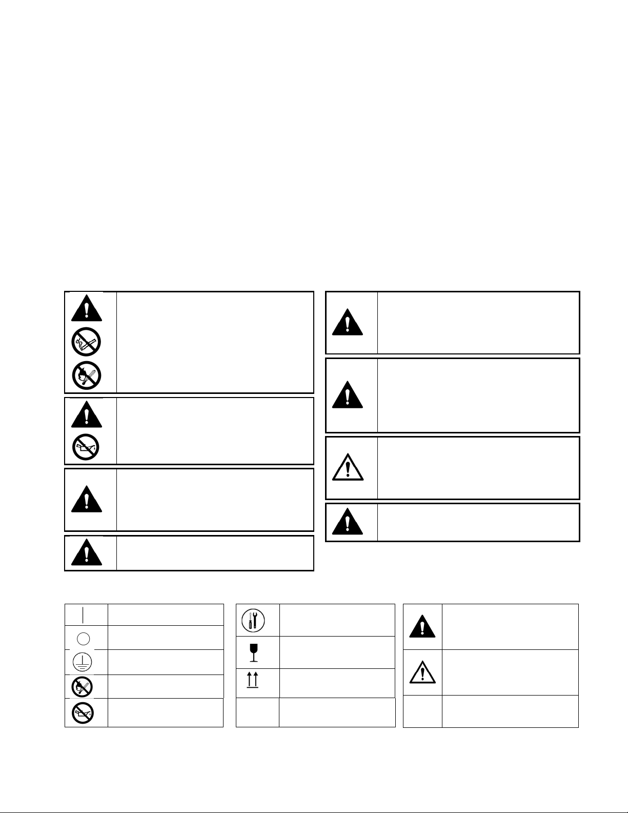
This device supplies highly concentrated oxygen
enriched product gas that promotes rapid
burning.
DO NOT allow smoking or open flames within the
same room of this device.
Failure to observe this warning can result in
severe fire, property damage, and / or cause
physical injury or death.
Oxygen accelerates the combustion of flammable
substances.
DO NOT use oil, grease, petroleum based or other
flammable products on the device.
This device is intended for industrial use. It
should be placed in a well-ventilated area, free
from smoke and atmospheric pollution, where
the intake filter ventilation is not obstructed or
blocked.
DO NOT use in an explosive environment.
DO NOT use in a magnetic environment.
DO NOT open the device while in operation.
Failure to observe this warning can result in
electrical shock.
DO NOT remove the cabinets unless you are a
qualified service technician.
DO NOT use extension cords or adapters. Use the
power cord provided.
Check that the electrical characteristics of the
power outlet used match those indicated on the
manufacturer’s plate on the rear panel of the
device.
This unit may be equipped with a polarized plug.
That is one blade wider than the other. If it does
not fit into the outlet, reverse the plug. If it still
does not fit, contact a qualified electrician. Do not
defeat this safety feature.
Only persons who have read and understood this
entire manual should be allowed to operate the
device.
1 Glossary of Symbols
ON (Power switched on)
OFF (Power switched off)
Class I (Protective Earth)
Do Not Expose to Open
Flames
Do Not Expose to Oil or
Grease
Tools Required /
Technician Only
FRAGILE – Handle with
Care
Keep in Vertical Position
IPX1 Protection from vertically
falling water drops
WARNING – A hazard or unsafe
practice that can result in serious
injury or death if conditions are
not avoided.
Caution - A hazard or unsafe
practice that can result in minor
injury and / or property damage if
conditions are not avoided.
Note – Information important
enough to emphasize or repeat

2010-2339NM Rev A 17 July 2018 Page 2 of 4
2 Purpose and Principles of Operation
This device is intended to supply oxygen for applications requiring high concentration. It produces an enriched
product gas by concentrating the oxygen contained in room air.
The operation of the device begins with air being pulled into the external air intake filter. This filtered air enters the
compressor via a suction resonator and fine filter. Pressurized air then exits the compressor and into an electronic
valve system that directs the air into one of two tubes that contain molecular sieve (sieve beds). The molecular sieve
adsorbs (physically attracts) the nitrogen from the air as it is pushed through the sieve beds. This allows the oxygen
enriched product gas to pass through before being delivered to the pressure regulator. As one tube is generating
the product gas, the other is being purged of the adsorbed nitrogen, this process is called pressure swing adsorption
(PSA). After passing through the regulator, the rate of product gas is set by the flow meter adjusting valve. Finally,
it passes through a fine particle filter (product filter) and then exits the device through a fire-resistant outlet.
3 Device Features
Features
1. Power Switch (On and Off)
2. Indicator Lights (Ok and Caution)
3. Circuit Breaker
4. Oxygen Outlet
5. Flow Knob (Pro 5 models only)
6. Flow Meter (with Adjustment Knob – Pro 8 and
10 models only)
7. Intake Ventilation
(consists of 10 – and 11 for Pro 5 models)
8. Technical Label
9. Power Cord
10. Cabinet Air Filter
11. Air Filter Grille
Accessories
Accessories used with this device must be oxygen
compatible and rated for the pressure. The filters
notated in this section, available from your distributor,
comply with these requirements.
Filters
Cabinet Air Filter – PN 8400-1025 / 9250-1025
Inlet Filter – PN 8400-1180 / 9250-1180
Product Filter – PN 7631-1053
4 Installation and Operation
The Pro Oxygen Generator is packaged to protect the device from damage while being transported and stored. After
the device is removed from the package, inspect for damage. If damage is detected, please contact your equipment
supplier.
The device should be placed and operated in a space where the Intake Filter Ventilation (7) is not obstructed and
the Power Cord (9) is accessible for easy disconnection but does not present a tripping hazard.

2010-2339NM Rev A 17 July 2018 Page 3 of 4
To use your device safely, follow the directions below.
1. Ensure that the Power Switch (1) is in the “O” (OFF) position.
2. Ensure the Intake Ventilation (7) is not obstructed or blocked.
3. Plug the Power Cord (9) into an outlet of the correct voltage and frequency as defined on the Technical
Label (8).
4. Connect supply tubing, that is rated for oxygen use at the designated pressure, to the Oxygen Outlet (4).
5. Move the Power Switch (1) to the “I” (ON) position.
6. Turn the Flow Knob / Flow Adjustment Knob (5/6) to the desired flow rate.
7. At the end of use, move the Power Switch (1) to the “O” (OFF) position to stop the device.
The required oxygen concentration is normally obtained within five minutes of the start up of the
device.
The oxygen enriched air flow continues for approximately one minute after shut down of the device.
5 Cleaning and Maintenance
Only the outside of the device is to be cleaned. After making sure the Power Switch (1) is in the "O"(OFF) position,
use a soft, dry cloth or, if necessary, a damp sponge with mild soap. Do not use acetone, solvents, abrasive
powders or any inflammable products to clean the cabinet.
The removable Cabinet Air Filter (10) must be cleaned, at least weekly, in warm water and household detergent. It
should be rinsed thoroughly and dried completely before reinstalling. The Inlet Filter (not pictured, located inside
the device) should be inspected monthly and replaced if required – at least annually. The product filter (not
pictured, located inside the device) should only be replaced by a technician if required (not common).
6 Performance Specifications and Alarm / Safety Features
Model 625 725 685 785 695 795
Description
5LPM
115V
5LPM
230V
8LPM
115V
8LPM
230V
10LPM
115V
10LPM
230V
Frequency 60Hz 50Hz 60Hz 50/60Hz 60Hz 50Hz
Average Power 330 Watts 300 Watts 500 Watts 490 Watts 700 Watts 600 Watts
Protection Class Class II
Mains Protection 10A 5A 10A 5A 10A 5A
Average Oxygen Content
At 2 LPM
> 90%
At 2 LPM
> 90%
At 2 LPM
> 90%
Average Oxygen Content
At 5 LPM
87% to 95.5%
At 8 LPM
87% to 95.5%
At 10 LPM
87% to 95.5%
Liter Flow 1 to 5 LPM 2 to 8 LPM 2 to 10 LPM
Outlet Pressure 12 Psig 15 Psig 20 Psig
Dimensions (L x W x H)
36 x 23 x 58.5 cm
(14 x 9 x 23 in.)
39 x 40 x 71 cm
(15 x 15.5 x 28 in.)
Weight 14.5 kg (32 lbs.) 24.5-26 kg (54-58 lbs.)
Indicator Lights (2) and Alarm Conditions
Green indicator: This light indicates that power is applied to the concentrator and that it is ready to provide oxygen
enriched product gas.
Yellow indicator: This light indicates that a system fault has occurred.
Power Failure detection: In the event of a loss of power, an intermittent audible alarm is activated (if equipped) and
the green light deactivates.
Process Failure detection: In the event of a process failure, an audible alarm and the yellow light is activated.
Electrical Protection: In the event of a surge or drop in power supply, the circuit breaker will trip. To restart the
device, depress the Circuit Breaker button (3).

2010-2339NM Rev A 17 July 2018 Page 4 of 4
7 Storage and Operating Conditions
The device should be stored in a dry area, with an ambient temperature between -20°C to 60°C (0°F to 140°F) at 15-
95% relative humidity. It must be stored, transported and used in the vertical position only. Oxygen concentration
can be affected after prolonged periods of storage – check device before use.
The device should be operated in a dry area, with an ambient temperature between 10°C to 40°C (50°F to 105°F) at
15-95% relative humidity. The device can be operated at an altitude of up to 1500m (5000ft) at a temperature of
21°C (70°F) without causing product degradation. Consult your equipment provider for further information
regarding 1500m to 4000m (5000ft to 13000ft).
8 Disposal
This device has been supplied by an environmentally aware manufacturer. A majority of the parts in the device are
recyclable. Follow local governing ordinances and recycling plans regarding disposal of the device or components
normally used in operation. Any accessories not original to the device must be disposed of in accordance with the
individual product markings for disposal.
9 Troubleshooting
OBSERVATIONS
POSSIBLE CAUSES
SOLUTIONS
The Power Switch (1) is in the “I” ON
position but the device does not operate.
The audible alarm sounds continuously
Power Cord (9) is not plugged into outlet
Power failure
Check that the device is properly
plugged into
the electrical outlet
Check the Circuit Breaker (3) and reset if
necessary
Yellow Light Indicator (2) remains lit
Product pressure or
concentration
is not
at an acceptable level Contact your Equipment Supplier
The audible alarm does not sound when
device is first turned on
Super capacitors not charged
Internal electrical fault
Leave device plugged in for approximately 10
minutes and retest.
Contact your Equipment Supplier
The device is operating but the Green Light
Indicator (2) is not lit Faulty indicator Contact your Equipment Supplier
The device is operating but there is no flow
(flowmeter ball not moving) Internal system failure
Stop device immediately and contact your
Equipment Supplier
The device is operating but the audible
alarm sounds continuously Internal fault
Stop device immediately and contact your
Equipment Supplier
The device suddenly stops and then starts
again in a few moments.
Dirty Filters
Compressor Thermal Shut-Off
Clean External Cabinet Filter (
10
)
Contact your Equipment Supplier
The oxygen flow is interrupted or the flow is
irregular
Tubing is disconnected or leaking
Tubing is restricted
Check tubing connections
Straighten tubing
Contact your Equipment Supplier
ProO2, LLC.
3949 Valley East Industrial Drive
Birmingham, Alabama 35217 U.S.A.
Tel: 205-856-7200 Fax: 205-856-0533
www.ProO2llc.com
This manual suits for next models
5


