PROAIM KITE-22-WONDER User manual

Instruction Manual
Kite-22 Wonder Package
(KITE-22-WONDER)

2
Subject Page
Foreword 3
Introducon 4
What’s in the box 5-6
Assembling 8-21
Warranty 22
At Proaim, our goal is to ensure 100% Customer Sasfacon in all that we do.
We back our sales with a 1 year warranty from the date of purchase and work hard
to resolve any problems in the unlikely event one should arise.
With our commitment to connuous improvement and your Feedback, building on
our reputaon of providing aordable, quality products is
PRIORITY #1.
Table of Contents

3
Welcome To Proaim!
Dear Client,
On behalf of all the people that work so hard to provide you with the most
up-to-date, exible and cost-ecient producon gear, we would like to welcome
you into the Proaim family.
By purchasing your kite-22 camera crane Wonder package, you have just joined a
host of designers, engineers, machinists, assembly, customer service and oce sta
that take great pride in all that they do. Our mantra of connuous improvement has
been the guiding principle of how we conduct our business since day one.
Once you have the opportunity to experience your kite-22 camera crane
wonder package, we hope you will agree that we cra quality products at a
compeve price. Products designed to meet and exceed the standards of today’s
real producon world.
Standards set by our valued clients and standards we strive to maintain.
With Best Wishes,
Proaim Team
4
Our Proaim Kite-22 Wonder Kit is our professional Video producon Camera Crane
that provides creaves with a exible shot selecon, easy set up and rugged long
life construcon. This best-selling lm camera crane comes with portable oor
camera dolly with 360-degree rotang wheels to add dynamic movement to your
shots. The 2-axis Pan Tilt head with remote control operaon features 360-degree
panning and lng movement with reversal point.
Proaim 22 Long Telescopic Camera Jib Crane
Proaim 150mm bowl Jib Stand with spreader (LW-150)
D 33 Pro Camera Dolly
Gold Pan and Tilt Head with Accessories (PT-GOLD)
Proaim Zoom Control (P-ZC-3DV)
Proaim Customized Storage cases for Camera Jib Arm , Jib Stand & Accessories
Complimentary Tools and Tool Pouch/Wrap
Introducon
Please inspect the contents of your shipped package to ensure you have received
everything that is listed below.
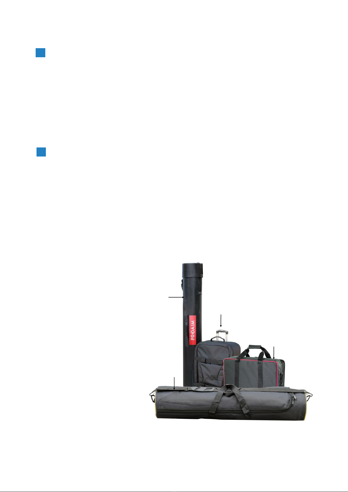
What’s In The Box
First Box includes
Jib Secons
Second Box includes
Jib Secons
Third Box includes
Accessories of Jib Crane
Fourth Box includes
Gravity Jib Stand
Fih Box includes
Dolly Pack
Sixth Box includes
Spin Pan-lt head
1
3
4
NOTE: We send the Jib secons in two boxes. One box has the secons with pipe packing and
the other box (cardboard box) has the rest of the secons. We only send one pipe packing for the
jib secons. We send the Dolly in cardboard box.
6

5
Packaging Material of Box 1 & 2: 7 x Jib Secons
Packaging Material of Box 3: Accessories of jib crane
Hub Mounng
Head Plaorm with bolt, sha collars, washers
and nut
6 x hank for joining arms
6 x locking Pins
Levelling Cable
Turnbuckle
Joysck controller bracket

6
Packaging Material of Box 5: Dolly
D-33 Pro Camera Dolly
Tripod holder
Joysck
Cable XLR Cable
Accessories
AC Adapter
Packaging Material of Box 6: Gold Pan and Tilt Head with Accessories (PT-GOLD)
Gold pan-lt head
Universal Adapter
Packaging Material of Box 4: LW-150 Jib Stand
with (P-RB-SP) spreader
LW-150 Jib Stand (P-RB-SP) Spreader

7
Safety Hints
ATTENTION: PLEASE READ THIS BEFORE USING TO PREVENT SERIOUS DAMAGE TO
THE GEAR!
The crane may not be assembled or operated under inuence of alcohol, drugs
or any other intoxicang substances. Lack of aenon while connecng the
components together can cause substanal damage to equipment/operator.
The crane may only be operated on levelled horizontal posion. Make sure that
the surface is stable.
To prevent any harm or injury, properly join all secons of the crane. It is
suggested to use the support stand while telescoping the complete length.
Always connect the steel cables properly to provide stability to the system.
They should not negavely impact the movements of crane in any way.
Aer setup of the crane, the pan-lt head / gimbal head shall be posioned
under the central pivot secon. In assembled state, when the pan-lt head /
gimbal head is higher than central pivot secon, there should be someone to
look aer the crane system.
The complete panning & liing range around it must be kept free. Avoid
anybody standing under the crane. No loose objects may be stored or placed on
it. Be very careful while using indoors.
Never operate the crane in the immediate vicinity of high-voltage power cables.
It holds danger to life.
Parcular care is required when operang the crane in unfavourable weather
condions. The crane must be shut down in sucient me. When it is used in a
rainy day, the pan-lt head / gimbal head and controlling bar shall be protected
against rain.
When you want to transport the crane, lock the Pan & Tilt Axis for safety. Make
sure that the components do not rub together and cause any material wear.
Before the counterweights are removed, ensure the remote head is resng on
the support stand. Then gradually remove the counterweights before remote
head, camera or other parts.
In the interest of safe crane operaon, avoid abruptly swivelling or stopping the
crane, otherwise it may cause serious damage to equipment.
FOLLOWING THESE GUIDELINES WILL PROVIDE BETTER SHOTS AND TROUBLE FREE
OPERATION.
SHOULD YOU NEED ADDITIONAL INFORMATION, TECHNICAL ASSISTANCE IS
AVAILABLE ‘ONLINE’ BY CONTACTING THE SALES REPRESENTATIVE.

8
12
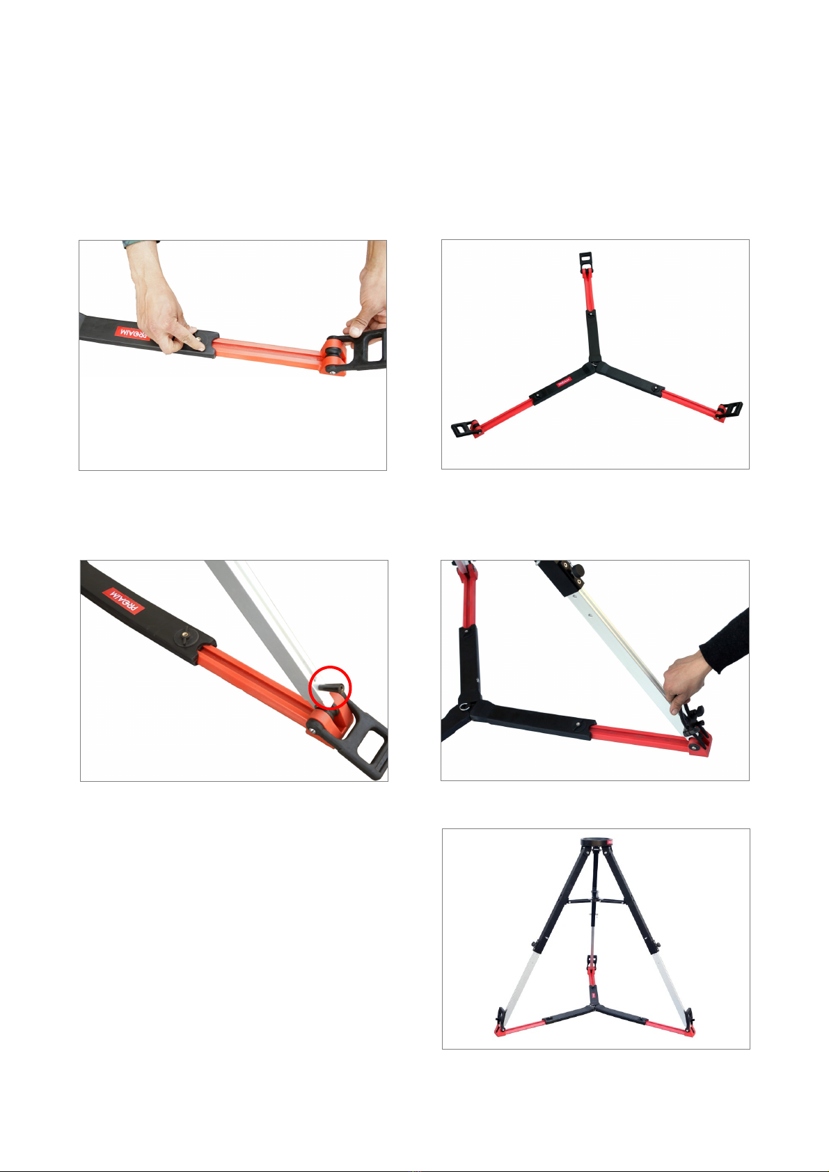
Now take out the Tripod Stand from its case, and stretch its legs on oor as per the
requirement. Then ghten the knob to secure it.
Match the holes of the boom leg secon with the upper leg secon to secure the tripod
stand with the Steel locking Pins and ghten the knobs.
34
Note: We have provided double locking
precauons on Jib Stand: Pin is the rst and
primary locking knob is the secondary
locking so rst lock the Pin to avoid slipping
of stand.
Assembling
5
Pin
Knob
9
6
For seng up your desired package with spreader or with oor dolly follow the below steps :
For Spreader
Take out the Spreader and spread it on oor and open the legs (as per your requirement) of
spreader with the help of provided knob.
7
89
Put the tripod stand on spreader & then lock it in place with the rubber grips. (Note: Tighten
the ratchet knob of stand to secure it with rubber grips.
Once all the above menoned steps are
completed, you will see the stand and
spreader as shown here.
10
10
11 12
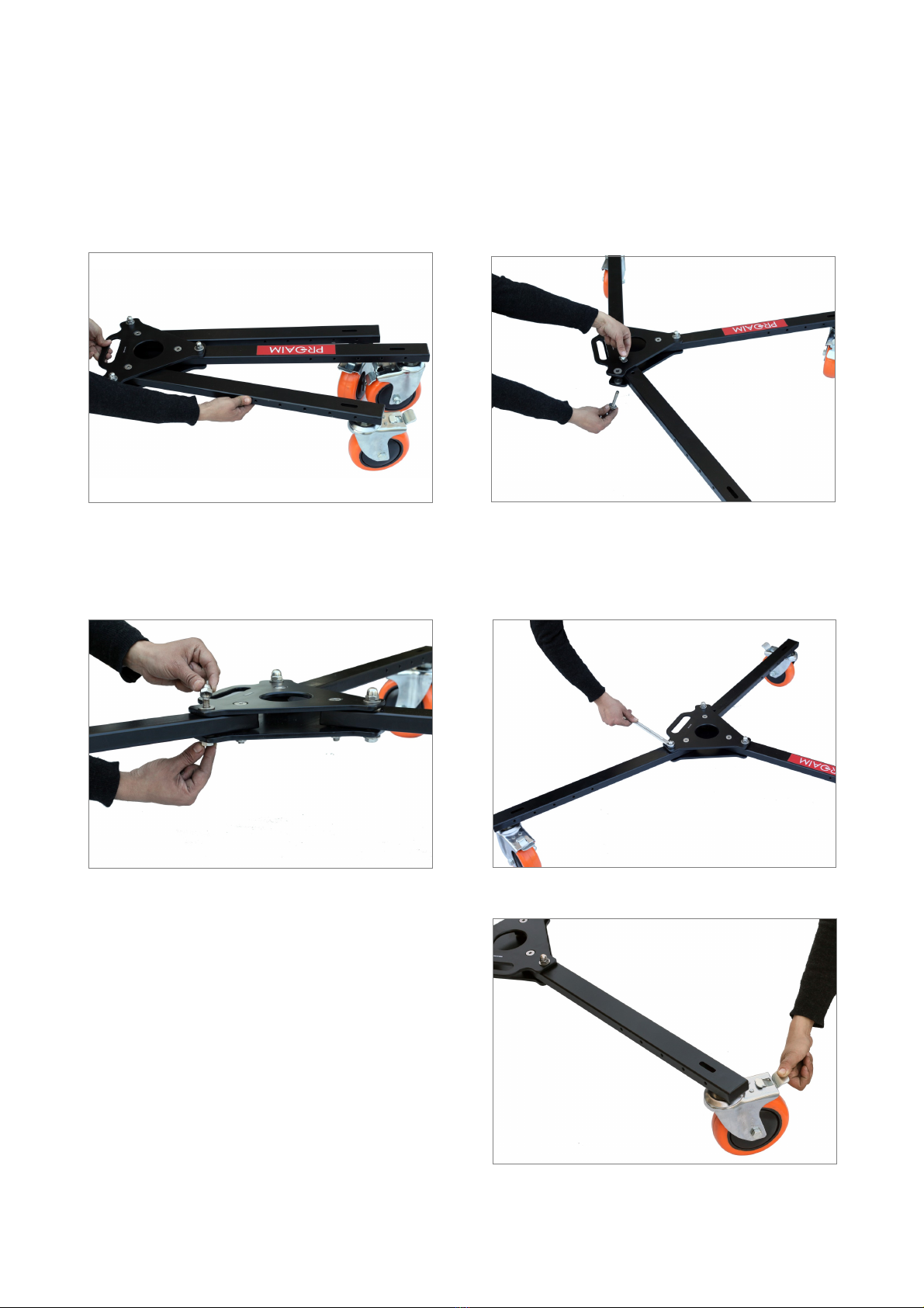
To open the legs of Dolly remove the bolts & fully spread it on oor.
13 14
Then insert the bolts with their washer and ghten the bolts properly.
For Dolly
NOTE : This dolly has various holes for exible mounng of Tripod.
15
NOTE: To keep the dolly in stac posion,
lock the wheels by pushing down the lever.

11
16 17
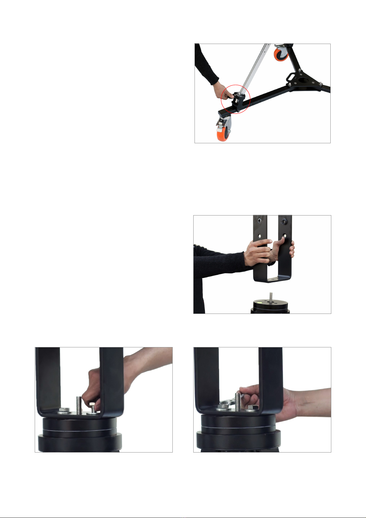
Remove the allen bolts from the Tripod holder.
18 19
Match the hole of Tripod holder with the dolly to insert the long bolt & ghten it with the
help of allen key.
20 21
Remove the ratchet knobs of the stand, Insert the tripod legs into the foots on the dolly.
12
22
Then ghten the provided knob.
23
Install the Hub Assembly by sliding from
the boom side into the stand’s Mount
opening.
HUB SECTION ASSEMBLY
NOTE: The Hub Assembly has several mounng holes. You can mount LCD Monitor or Joysck
box to this assembly if you want.
24
Insert the bolts with washers and ghten properly with the help of Wrench .
25
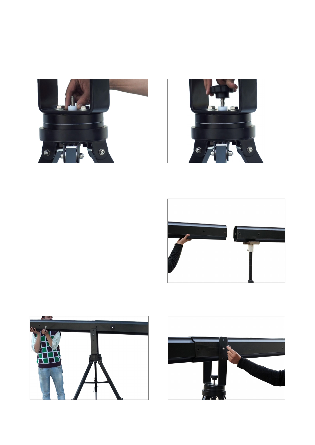
13
26
Insert the provided washer & knob to secure the jib properly.
INSTALLING THE JIB SECTIONS
27
NOTE: This is the Pan Fricon Knob. Never pan the Jib with this knob ghtened. If this knob
turns while panning, it is too ght. Only ghten while parking the jib !
Insert the rear tube secon (secon 1)
into the hub assembly, slide secon 2
into secon 1 and align the holes of the
Secon 1 and secon 2 with the central
hole of hub assembly.
21
28
Already aached 1st or 2nd jib secons, insert it onto the hub then insert the long bolt and
nut to Secure the secons properly.
1
26 30
12
29

14
Aer alignment of holes (Jib arms) insert hank lock pin & ghten it from another side with
hank threaded cap. For double security insert the locking pin from the top of jib arm.
31 32
NOTE: We have provided double locking precauons on Jib, Knob is the rst and primary pin is
the secondary locking so rst lock the knob to avoid slipping of secons.
Repeat this process for rest of the secons. Aach them towards the other Secon 6 with 5 ,5
with 4 , 4 with 3 , 3 with 2 & 2 with 1 :
33 34
12
3
Remove the bolt from the head secon then aach with the jib.
35 36
ATTACHING HEAD SECTION

15
Aach the provided bolt, sha collars, washers and nut. Tighten all the Allen bolts and nuts to
secure properly as shown in the image.
37 38
Connect the one end of Head Plaorm Levelling cable with the head plaorm by hooking the
turnbuckle ends.
39 40
And the other end aach with the hub
assembly.
41
16
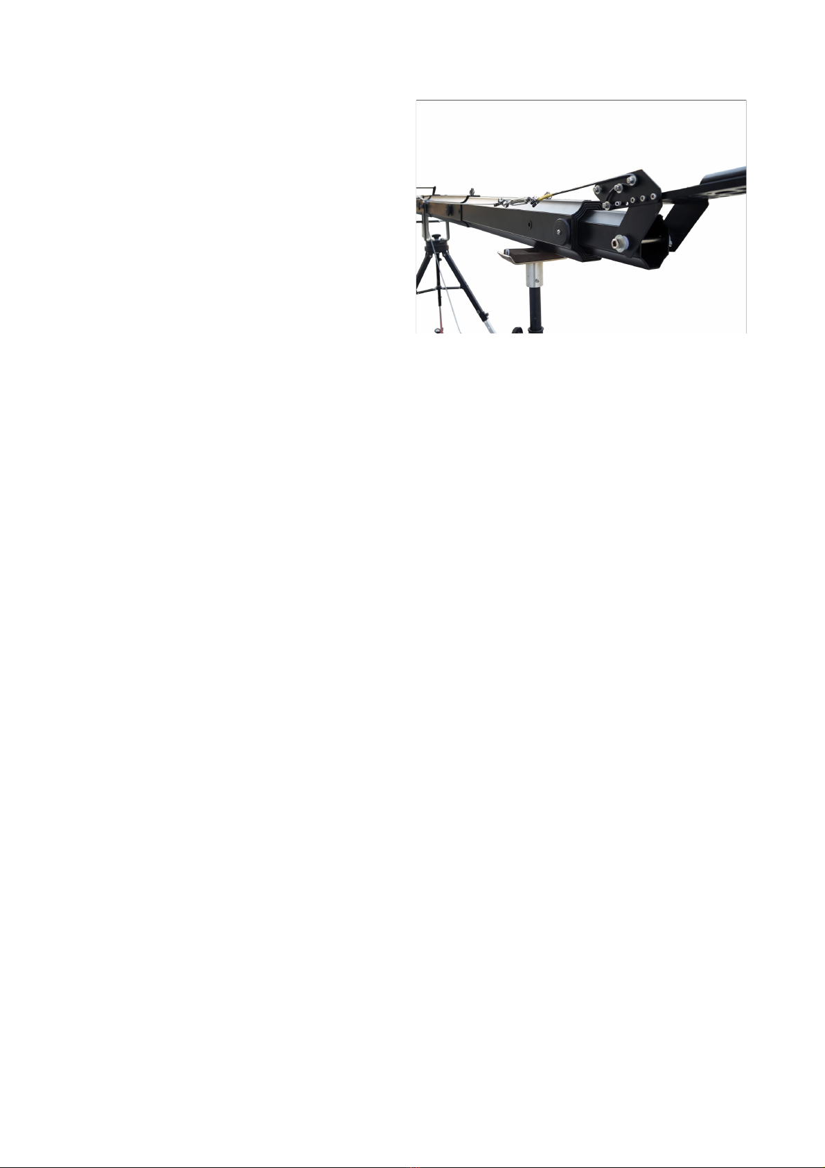
INSTALLING THE REAR FRAME
To mount the Rear secon, of jib secon and insert the bolt with washers through one end
of the secon to the other. Slide the bolt through and hand ghten.
42 43
44
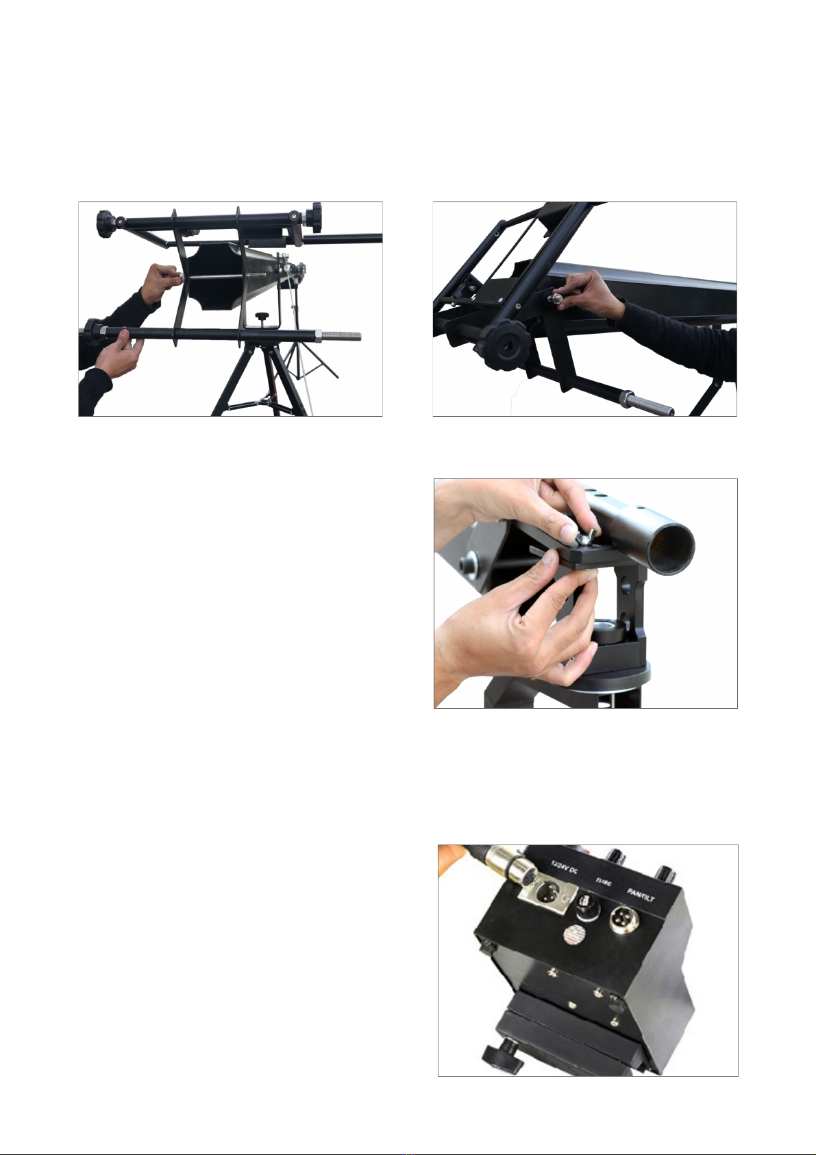
INSTALLING THE PAN TILT HEAD
Aach the PROAIM GOLD PAN TILT
HEAD base plaorm to the Tripod or
jib arm using the four ¼”screws.
Tighten to secure.
Adjust the mounng extension so that the pan motor is in the rear facing posion before
mounng.
Install your cable starng at the camera end; leaving enough cable slack for the camera for
full pan & lt movement, you may need to add Velcro to loop the cable around the jib arm.
Install the 12 volt DC power (4 pin
XLR) in rear of Joystick Box.
Note: Any 12 volt battery may operate
the PROAIM™ GOLD PAN TILT HEAD as
long as the connector mates and is #1 pin
Negative and #4 pin Positive.
CABLES & CONTROL BOX
45

17
CAUTION: DO NOT USE A UNREGULATED POWER SUPPLY! IF USING A REGULATED POWER
SUPPLY IT MUST PRODUCE LESS THAN 12 VOLTS. MORE THAN 24 VOLTS MAY CAUSE
PERMANENT DAMAGE.
The joystick may be operated hand held, from a flat surface like a table top or attached to
the boom arm of the jib.
PROAIM™ GOLD PAN TILT HEAD Digital
only
Attach the 4-pin power cord to rear of
joystick box.
JOYSTICK
HEAD CABLE
Aach the head cable to the cable
connected to the gold pan lt head for
panning & lng.
If the joysck control is opposite, undo
the connectors at the motors, rotate
180 degrees and re-install.
Aach & secure your camera on the
camera plaorm of Head with the help
of provided bolt.
46
47
48
18
BALANCING
Follow these steps to balance the head:-
Find the horizontal balance point of your camera by using 2 ngers of one handing while
holding the handle.
Mark this point on the side of the camera with chalk or tape.
Turn the unit on and move the lt control unl the camera plate is vercal.
Loosen the two screws holding lt motor. (DO NOT REMOVE).
Grasp the motor and turn slightly to disengage gears.
Mount the camera to the camera plate with the screw provided.
Tighten by threading the nut up to the boom of the camera plate securely.
Make sure your balance point previously marked with chalk or tape is in the middle of the
plate.
Loosen the knob below the camera plate and slide the camera and plate up or down unl the
center line of your camera is about in the middle of the large gear. Now ghten knob.
If the camera is perfectly balanced it will stay in any posion while motor gear is sll
unaached.
Grasp the motor and turn it back unl the gears mesh.
Gently ghten motor screws.
Secure the camera.
Note: All reducon boxes have a small amount of backlash. The balancing of the camera will
reduce the backlash to a minimum making it felt at the top of the lt arc.
As each secon is pulled from the
previous secon, you can store
unused secons in the tail as ballast
weight and lighten your
counterweight demand.
OPERATION
With the camera set up as previously described above, Power ON by pressing the RED
Switch on the top of the Joysck control box.
For inverted use, disconnect the leads to the motors, rotate the control box 180 degrees
and re-install.
Note: Remember pracce makes perfect and always watch the cables for binding.
The PROAIM™ GOLD PAN TILT HEAD circuitry is built enrely into the joysck box. The only other
requirement is the AC power pack (provided) or baery power. The power pack can handle
90-240 volts. Users will need the appropriate plug adapter for local use.
49

19
JOYSTICK
The joystick is a two-axis variable speed servo controller. The further you move in one direction
the faster the output to that motor. This will be a little tricky at first, but little practice will
improve your success.
The joystick may be operated in a handheld position or from a flat surface such as a tabletop, or
attached to the boom arm of Jib.
After plugging the power cord into a proper outlet, press ‘power on. The LED light on the
control box should illuminate and the head may jump slightly on start up or shut down. This is
normal. This can be controlled by Dead Spot. Adjust the joystick to ensure correct movement
of the head. It may be necessary to reconnect to the motors if required.
POWER CONTROL
To the right and above the joystick is a knob labeled "SPEED".
This is the power control knob. Turning to the right will be full power and back to the left will
decrease the available power to both pan and tilt operation. The advantage of power control is
to be able to limit power when only slow accurate movements are needed. With the power
control at half power (approx. 8 volts max. output) the full range of motion on the joystick will
be between 0 and 8 volts making finer adjustments possible. The power control will be usable
between a range of approximately 4 volts to 12 volts.
DEAD SPOT
The knob to the left is marked Dead Spot. Turned all the way to the left (counterclockwise) will
create the smallest dead spot. Meaning that the head will begin to move as soon as the
smallest deflection of the joystick is made. Moving to the right will increase the area where no
power is sent to the head motors. At half way, the dead spot will close again, this helps to
avoid crossing the tilt when only pan movement is desired.
The dead spot is so tight when the control knob is all the way to the left, it may be necessary to
back it off slightly until no movement is seen in either axis.
Note: With the dead spot all the way left the head may move in both axis on it’s own. The
dead spot should be set at approx. the 9:00 position to insure that no unwanted
movement occurs.

20
Linear or Logarithmic taper joysck control
All joyscks are linear, meaning that each degree of movement of the sck correlates to the
output. On the 12 volt PROAIM PAN TILT HEAD half deecon of the joysck means
approximately 6 volts sent to the motors. But with the advent of Digital we can now control the
taper of the joysck, making in Logarithmic as well. Logarithmic taper being that the rst of
joysck movement only sends a small amount of power to the motors and the last of the
deecon will send more power per degree of deecon. On Logarithmic taper 1/3 of joysck
deecon might yield 2 volts output the next 1/3 will yield 4 volts output and the last 1/3 of
yields 6 volts for a max. again of 12 volts. This mode gives the operator ne slow movements
yet retains the ability to go to max. speed if necessary.
PAN DIRECTION SWITCH
When the Pan-Tilt Head is used on a Tripod or on a Jib.
When the head is shied from a Jib to a tripod, it needs reversal of direcon as the locaon of
the head will be inverted. By switching “on” the pan direcon switch, we can immediately
reverse the direcon. When the joysck is moved to the right it gives right rotaon as it gives
while mounted on the tripod directly.
Counterweights
The Jib is setup with “plate weights” or bar bells” style weights. Plate weights come in several
weights and diameters. They get smaller as the weights get lighter. The largest (25lbs) is about
11 inches in diameter. The mounng hole is 1” in diameter for all weights. The jib has a varying
weight rao depending on the length you have chosen. The 24.5 arm itself balances at about
121.5 lbs. Just mulply the weight, of the addional items you will put on the end of the arm,
by 5 and you will know how much weight to buy. Buy a few extras in case you add other
accessories. The lighter weights will allow you to “ne tune” once you’re ready to go.
Other manuals for KITE-22-WONDER
1


