Safety Instruction
Specification
Operation
Troubleshooting
Parameters
Part List
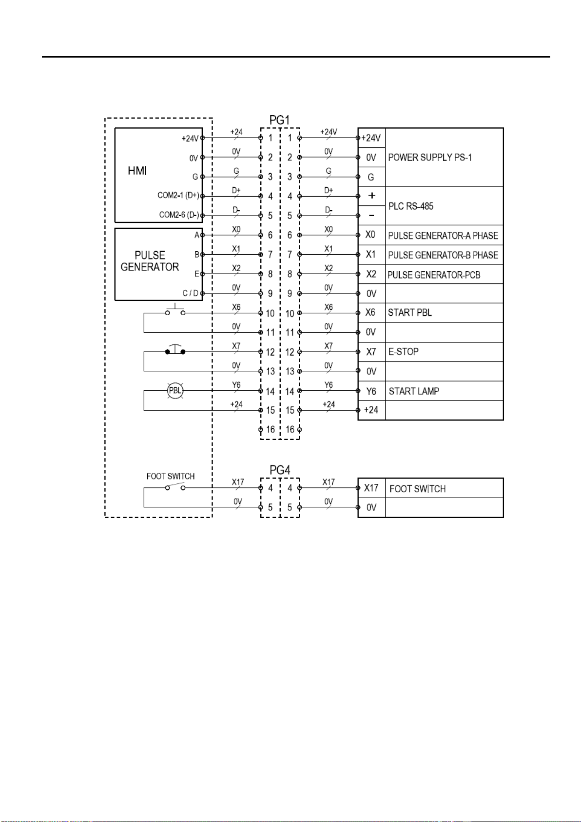
Circuit
Instruction................................................................................................................i
Protection................................................................................................................ii
1.1 Specifications....................................................................................................1
1.2 Control Box Specification...................................................................................2
1.3Connector..........................................................................................................3
2.1 HMI....................................................................................................................6
2.2 Main Screen......................................................................................................7
2.3 Manual Mode.....................................................................................................8
2.4 Auto Mode.........................................................................................................9
2.5Setting..............................................................................................................10
2.6Program Save/Load..........................................................................................11
2.7 Program Note...................................................................................................12
2.8Welding Sequence Setting ...............................................................................13
2.9Welding Current Setting....................................................................................14
2.10 Index Weld Setting .........................................................................................15
2.11 Autorun Function............................................................................................16
2.12 Password Setting............................................................................................17
2.13Program Backup.............................................................................................18
2.14 System Setting ...............................................................................................19
2.15 System Information.........................................................................................20
2.16 HMI Update....................................................................................................21
2.17PLC Update....................................................................................................22
2.18Alarm History..................................................................................................23
2.19 I/O Monitor......................................................................................................24
3.1Error Message..................................................................................................25
3.2 Troubleshooting................................................................................................26
4.1 PT Servo Amplifier Parameters ........................................................................27
5.1Part List - PT200s Mechanism..........................................................................28
5.2 Part List - HMI and Remote ............................................................................29
5.3 Part List - Control Box .....................................................................................30
6Circuit..................................................................................................................31