Mweld POWER CUT 60HFIII User manual

POWER CUT 60/70HFШ
WARNING:
Read carefully and understand all ASSEMBLY
AND OPERATION INSTRUCTIONS before
operating. Failure to follow the safety rules and
other basic safety precautions may result in
serious personal injury.
OWNER’S MANUAL
WELDING AND CUTTING TOTAL SOLUTION


1
CATALOGUE
GENERAL SAFETY RULES
PRODUCT INTRODUCTION
SAFETY OPERATION
TECHNICAL SPECIFICATIONS
INSTALLATION
OPERATION
TROUBLE SHOOTING
LISTOF SPARE PARTS
CIRCUIT CHART
COMPLETE SET SPECIFICATION
TRANSPORT& STORAGE

2
GENERAL SAFETY RULES
WARNING:Read and understand all instructions. Failure to follow all instructions listed
below may result in serious injury.
CAUTION:Do not allow persons to operate or assemble this POWER CUT 60/70HFШ
until they have read this manual and have developed a thorough understanding of how the
POWER CUT 60/70HFШworks.
WARNING: The warnings, cautions, and instructions discussed in this instruction
manual cannot cover all possible conditions or situations that could occur. It must be understood
by the operator that common sense and caution are factors which cannot be built into this product, but
must be supplied by the operator.
SAVE THESE INSTRUCTIONS
IMPORTANT SAFETY CONSIDERATIONS
1.1 Your Welding Environment
-Keep the environment you will be welding in free from flammable materials.
-Always keep a fire extinguisher accessible to your welding environment.
-Always have a qualified person install and operate this equipment.
-Make sure the area is clean, dry and ventilated. Do not operate the welder in humid, wet or poorly
ventilated areas.
-Always have your welder maintained by a qualified technician in accordance with local, state and
national codes.
-Always be aware of your work environment. Be sure to keep other people, especially children, away
from you while welding.
-Keep harmful arc rays shielded from the view of others.
-Mount the welder on a secure bench
or cart that will keep the welder secure and prevent it from tipping over or falling.
1.2 Your Welder’s Condition
-Check ground cable, power cord and welding cable to be sure the insulation is not damaged. Always
replace or repair damaged components before using the welder.
-Check all components to ensure they are clean and in good operating condition before use.

3
1.3 Use of Your Welder
Do not operate the welder if the output cable, electrode, torch, wire or wire feed system is wet. Do not
immerse them in water. These components and the welder must be completely dry before attempting to
use them.
-Follow the instructions in this manual.
-Keep welder in the off position when not in use.
-Connect ground lead as close to the area being welded as possible to ensure a good ground.
-Do not allow any body part to come in contact with the welding wire if you are in contact with the
material being welded, ground or electrode from another welder.
-Do not weld if you are in an awkward position. Always have a secure stance while welding to prevent
accidents. Wear a safety harness if working above ground.
-Do not drape cables over or around your body.
-Wear a full coverage helmet with appropriate shade (see ANSI Z87.1 safety standard) and safety
glasses while welding.
-Wear proper gloves and protective clothing to prevent your skin from being exposed to hot metals, UV
and IR rays.
-Do not overuse or overheat your welder. Allow proper cooling time between duty cycles.
-Keep hands and fingers away from moving parts and stay away from the drive rolls.
-Do not point torch at any body part of yourself or anyone else.
-Always use this welder in the rated duty cycle to prevent excessive heat and failure.
1.4 Specific Areas of Danger, Caution or Warning
Electrical Shock
Electric arc welders can produce a shock that can cause injury or death. Touching
electrically live parts can cause fatal shocks and severe burns. While welding, all metal
components connected to the wire are electrically hot. Poor ground connections are a hazard, so secure
the ground lead before welding.
-Wear dry protective apparel: coat, shirt, gloves and insulated footwear.
-Insulate yourself from the work piece. Avoid contacting the work piece or ground.
- Do not attempt to repair or maintain the welder while the power is on.
-Inspect all cables and cords for any exposed wire and replace immediately if found.
-Use only recommended replacement cables and cords.
-Always attach ground clamp to the work piece or work table as close to the weld area as possible.
-Do not touch the welding wire and the ground or grounded work piece at the same time.
-Do not use a welder to thaw frozen pipes.
Fumes and Gases
-Fumes emitted from the welding process displace clean air and can result in injury or death.
-Do not breathe in fumes emitted by the welding process. Make sure your breathing air is clean and safe.
-Work only in a well-ventilated area or use a ventilation device to remove welding fumes from the
environment where you will be working.
-Do not weld on coated materials (galvanized, cadmium plated or containing zinc, mercury or barium).
They will emit harmful fumes that are dangerous to breathe. If necessary use a ventilator, respirator with

4
air supply or remove the coating from the material in the weld area.
-The fumes emitted from some metals when heated are extremely toxic. Refer to the material safety data
sheet for the manufacturer’s instructions.
-Do not weld near materials that will emit toxic fumes when heated. Vapors from cleaners, sprays and
degreasers can be highly toxic when heated.
UV and IR Arc Rays
The welding arc produces ultraviolet (UV) and infrared (IR) rays that can cause injury to your
eyes and skin. Do not look at the welding arc without proper eye protection.
-Always use a helmet that covers your full face from the neck to top of head and to the back of each ear.
-Use a lens that meets ANSI standards and safety glasses. For welders under 160 Amps output, use a
shade 10 lens; for above 160 Amps, use a shade 12. Refer to the ANSI standard Z87.1 for more
information.
-Coverallbareskinareasexposedtothearcwithprotectiveclothingandshoes. Flame-retardant cloth
or leather shirts, coats, pants or coveralls are available for protection.
-Use screens or other barriers to protect other people from the arc rays emitted from your welding.
-Warn people in your welding area when you are going to strike an arc so they can protect themselves.
Fire Hazards
Do not weld on containers or pipes that contain or have had flammable, gaseous or liquid
combustibles in them. Welding creates sparks and heat that can ignite flammable and
explosive materials.
-Do not operate any electric arc welder in areas where flammable or explosive materials are present.
-Remove all flammable materials within 35 feet of the welding arc. If removal is not possible, tightly cover
them with fireproof covers.
-Take precautions to ensure that flying sparks do not cause fires or explosions in hidden areas, cracks or
areas you cannot see.
-Keep a fire extinguisher close in the case of fire.
-Wear garments that are oil-free with no pockets or cuffs that will collect sparks.
-Do not have on your person any items that are combustible, such as lighters or matches.
-Keep work lead connected as close to the weld area as possible to prevent any unknown, unintended
paths of electrical current from causing electrical shock and fire hazards.
-To prevent any unintended arcs, cut wire back to ¼" stick out after welding.
Hot Materials
Welded materials are hot and can cause severe burns if handled improperly.
-Do not touch welded materials with bare hands.
-Do not touch MIG gun nozzle after welding until it has had time to cool down.
Sparks/Flying Debris
Welding creates hot sparks that can cause injury. Chipping slag off welds creates flying debris.
-Wear protective apparel at all times: ANSI-approved safety glasses or shield, welder’s hat and ear plugs
to keep sparks out of ears and hair.

5
Electromagnetic Field
-Electromagnetic fields can interfere with various electrical and electronic devices such as
pacemakers.
-Consult your doctor before using any electric arc welder or cutting device
-Keep people with pacemakers away from your welding area when welding.
-Do not wrap cable around your body while welding.
-Wrap MIG gun and ground cable together whenever possible.
-Keep MIG gun and ground cables on the same side of your body.
Shielding Gas Cylinders Can Explode
High pressure cylinders can explode if damaged, so treat them carefully.
-Never expose cylinders to high heat, sparks, open flames, mechanical shocks or arcs.
-Do not touch cylinder with MIG gun.
-Do not weld on the cylinder
-Always secure cylinder upright to a cart or stationary object.
-Keep cylinders away from welding or electrical circuits.
-Use the proper regulators, gas hose and fittings for the specific application.
-Do not look into the valve when opening it.
-Use protective cylinder cap whenever possible
1.5 Proper Care, Maintenance and Repair
-Always have power disconnected when working on internal components.
- Do not touch or handle PC board without being properly grounded with a wrist strap. Put PC board in
static proof bag to move or ship.
-Do not put hands or fingers near moving parts such as drive rolls of fan
POWER CUT 60/70HFШUSE AND CARE
Do not modify the POWER CUT 60/70HFШin any way. Unauthorized modification may impair the
function and/or safety and could affect the life of the equipment. There are specific applications for
which the POWER CUT 60/70HFШwas designed.
Always check of damaged or worn out parts before using the POWER CUT 60/70HFШ.Broken parts
will affect the POWER CUT 60/70HFШoperation. Replace or repair damaged or worn parts
immediately.
Store idle POWER CUT 60/70HFШ. When POWER CUT 60/70HFШis notin use, store it in a secure
place out of the reach of children. Inspect it for good working condition prior to storage and before
re-use.

6
Product Introduction
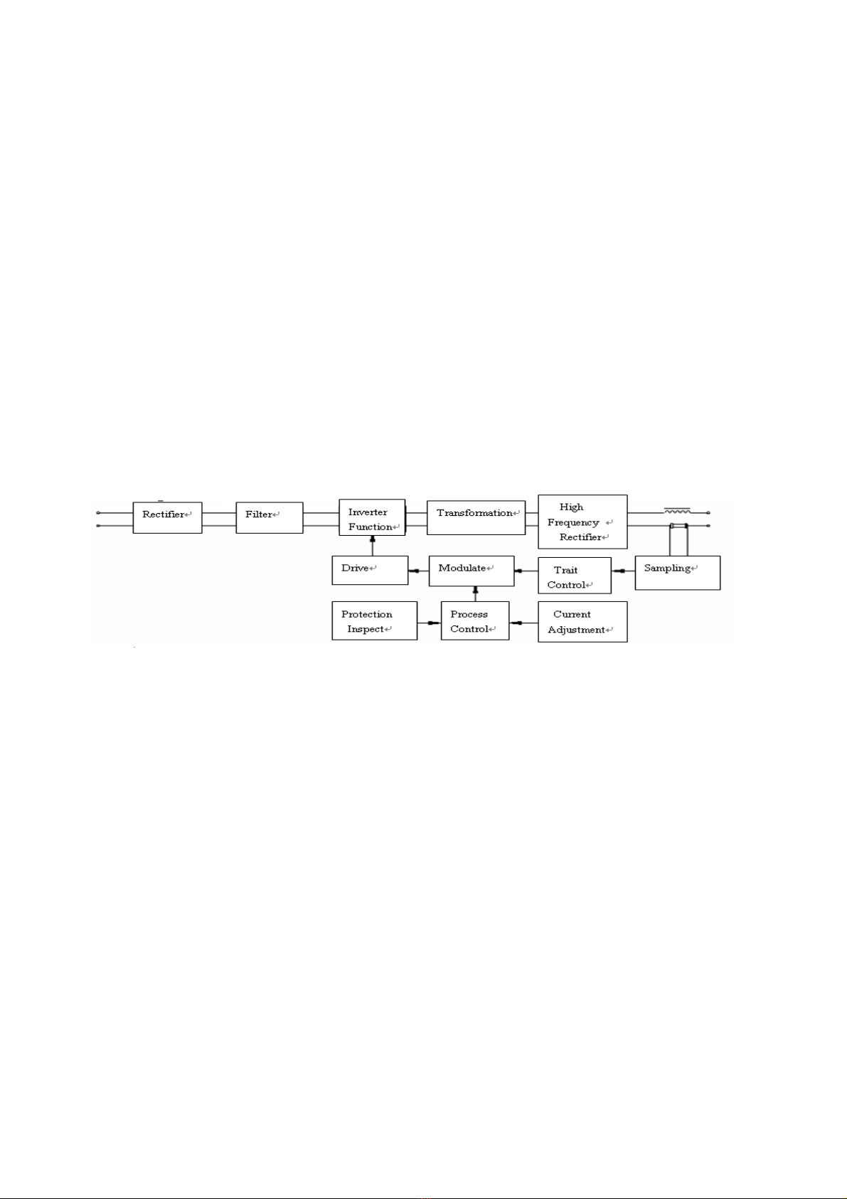
POWER CUT series isregarded as metal cutter equipment with high efficiency. Its working principle is to use
the compressed air as the ionization medium, and then form the high density plasma arc heat source by the torch
nozzle’s compress effect, which melt the metal as a result. The melted metal will be blown off by the high speed
gas flow at the same time to form into narrow cutting slot, thus the metal can be melted and cut very rapidly.
This series cutting equipment possesses good features like easy operation, energy saving, high speed cutting,
narrow and glabrous cutting slot, less deformation of work pieces, reliable and safe apply, low investment etc. It is
suitable for almost all metal plate and pipe materials, including mild steel, stainless steel, aluminum, copper,
titanium, nickel alloy, cast iron etc. It is widely used in every work of life such as ship building, motor
manufacturing, metal structure, boiler, pressure vessel and pipe making, medical appliance and machinery making
etc.
The feature of POWER CUTseries:
◇Small and light ,the weight of POWER CUT 60/70HFШis only 18Kg.
◇advanced IGBT inverter technology attributes to stable capability ,high efficiency and energy
saving
◇workcanbereliableat ±15% of fluctuation for input voltage.
◇visible gas adjustment and easy operation, specially suitable for decoration。
◇Thecutting thickness capacity of machine typewill reach 22mm.
◇cutting slot both narrow and glabrous;no damage to the work pieces. Commendatory thickness attributes to
high quality.
◇Complete protective function. include the protections of overheat.
Safety Operation
Operator’s Self Protection
*Please always follow the rules that conform to safety and hygiene. Wear protective garments to avoid injuries
to eyes and skins
*No touch to the working piece while operation in case of the electric leaking accident occurred
*No touch to the two output polarity (The polarity of the torch and the polarity of the work piece.) at the same
time without any insulationprotection.
*No permission to cut the vessel with inflammable and explosive materials or the sealed pressure vessel.
*Avoid operation under water or high humidity places.
*Shut off the power supply before changing the connect tip or electrode.
*Prohibit aiming the torch at any part of the body.
*Prohibit touching the contact part of the torch after the cutter is on.
Attention
*POWER CUT 60/70HFШseries cutter is electronic products whose spare parts are very tender, do not change
oradjust with a rush otherwise the switch will be damaged.
*Check the connection to see if it is well connected, whether the earth (ground) connection is reliable, etc.
*Fumes and gases produced when cutting are hazardous to health. Make sure to work in places where there are
exhaust or ventilation facilities to keep fumes or emissions away from the breathing zone.

7
*Insulate the working area since spatter will be occurred.
*No access to switching or modulating by others while the cutter is working
*Cutters have strong electromagnetism and frequency interference, so keepawaypeoplewithheartpaceorthe
articles which can be interfered by electromagnetism and frequency.
*No squeeze or punch to the cutting cable.
*Never clean the slag in the torch head by violent knocking.
*The puckering angle of the torch cable can not be too small, otherwise the inside cable of gas pipe will be
damaged which can result into accident.
*Never allow anybody else other than the operator himself to access the job site.
*No touching on the output connection or any other electrification parts while welding.
Safety Measures to Be Taken To Assure the Correct Installation and
Position
*Precaution must be taken to keep the operator and the machine from the foreign materials falling from up
above
*The dust, acid and erosible dirt in the air at the job site can no exceed the amount required by the norm
(excluding the emission from the cutter).
*The cutting machine must be installed in the place where it can no be exposed to sun and rain. Also it must be
stored in less humid place with the temperature range at -10~+40℃.
*There should be 50cm space left for the cutting machine to have good ventilation.
*Make sure that there is no metal-like foreign body to enter the cutting machine.
*No violent vibration in the cutter’s surrounding area.
*Make sure the machine is installed in where it won’t interfere the surrounding electromagnetism equipment
during the operation.
*Take measures to prevent wind while operating in the strong wind since the cutter is gas shielded.
Safety Check
Each item listed below must be carefully checked before operation:
*Make sure that the cutting machine has reliable earth connection.
*Make sure that there is always sound output and input wire connection instead of exposing outside.
Regular check needs to be conducted by the qualified personnel after the cutter has been installed over a
period of six months, which involves as follows:
*Routine cleaning is required to make sure there is no abnormal condition happeninginthetightenedplaces
such as the loose and slipped magnetic core, regulating screw, connecting wire happening in the cutting
machine.
*The external parts installed on the cutter’s panel must guarantee that the welder works properly.
*Fresh the cable of the cutter if it is worn out..
*Any damage to the input cable if occurred should be dealt safely.
*Make sure whether there is enough power supply to make the cutting machine work properly, and the power
supply connected into the cutter should be equipped with safety protectiondevice.
Notice: Cut off the power supply before opening the case to check.
Please do not hesitate to contact us for technical assistance whenever you come across the problems you can
not work out or you may deem difficult to fix.

8
Technical Specifications
Environment for the Product
*The surrounding temperature range:
When cutting: -10~+40℃
During transport or in storage: -25~+55℃
*Relative humidity:
When at 40°C:≤50%
When at 20°C: ≤90%
*The dust, acid and erosible materials in the air can not exceed the amount required by the norm (apart from the
emissions from the cutter ). No violent vibration at the job site.
*Keep from raining when it is used outdoor.
Requirement for Main Supply
*The voltage oscillogram should display actual sine wave.
*The oscillation of the supplied voltage should not exceed ±20% of the rated value.
*The imbalance rate of three phases main supply should not less than 0.5%.
*Frequency fluctuation should be less than ± 2%..
Theory of Cutting Machine(seetheprinciplechart
)
The principle chart
POWER CUT Series Air POWER CUT 60/70HFШis high speed cutting equipment with advanced technology
which is using high density plasma arc as source of the heat. The plasma arc would be acquired by the compressed
air as ionization medium and the compression of the torch’s nozzle.
The main electric theory of POWER CUT 60/70HFШ:400V 3-phase industrial AC power is required, and transfer
to DC after rectified by Single phase rectification bridge and transformed by the middle frequency transformer,
and then rectified to the DC by the fast recovery diode, While starting cutting,thenozzleandelectrodeare
separated quickly by the air pressure, the voltage between them make the air are ionization and arc which is
moved between work piece and electrode pilots .
Cutter’s Structure
POWER CUT 60/70HF Шapplies portable box structure: digital display, protect indictor light, the cutting
current adjust knob,are installed on the first half of the front board; and the current output ‘+’ electrode quick
connector, ‘-’ electrode quick connector, cuttingtorch control(two pins socket), switch socket are installed on the
next half; the power inlet,Impressed gas input connector and power switch, are installed on the back board; the
control transformer,control press circuitry board can be seen on the first installation board after shelling the out
case;the rectification bridge etc. are installed on the bottom, the medium frequency transformer, fast recovery
rectifiers, heat sink etc. are installed in the centre of the box.
Cutter Type Coding
*Combination of the English letter and the Arabic numerals.
*Implication of Coding:

9
Main Technical Data
Items
Type
Unit
POWER CUT 60HFШPOWER CUT 70HFШ
Rated input voltage V 400 400
Power supply frequency Hz 50/60 50/60
Phase PH. 3 3
Rated input capacitance KVA 8.6 9.4
Rated input current A 12.5 13.5
Output non-load voltage V 330 330
Rated operation voltage V 104 108
Output Current A 25-60 25-70
Gas flow L/min 300 300
Air pressure MPa 0.3~0.6 0.3~0.6
Lag gas time S 5~15 5~15
Max cutting thickness mm 22 25
Rated duty cycle % 60 60
Cooling type Fan-cooled Fan-cooled
Arc start type High-frequency transfer arc High-frequency transfer arc
Insulation grade grade F F
case Protection Class IP IP21S IP21S
Weight kg 22.7 22.7
Dimension (L*W*H) mm 550*245*405 550*245*405
Applying Norm of Cutter
POWER CUT 60/70HFШconforms with the following standard to perform EN 60974-1.
Installation & Maintenance of the Torch & Replacement of the Spare
Parts
Please notice: Please make sure the power supply switch is off before loading/unloading the cutting torch and
replacing the spare parts.
*The installation of the torch’s spare parts should follow the order according to the pictures listed blow. Please
notice during the installation: the distributor should not be installed in reverse, and the protection cover should
be screwed tightly, but please be alert that over pressure would smash the distributor.
*While the nozzle’s hub hole is burnt to a degree that it will affect the cutting slot, it should be replaced in time
*The electrode should be replaced in time when it worn down or be shortened to about 2mm, otherwise the
torch will be broken. (See the following pictures.)

10
Cutting Torch Assemble Sketch
*If there are any spare part s or the distributor are broken, they should be replaced in time.
*The torch’s cable, working gas pipe, protection cover or the wire are broken, then they should be replace in
time
Remark of Illustration
Ground
Descending
Plasma Cutting
Power Source & AC 1 Phases
3Phases Arc Welding transformer -- Rectifier
DC
X:Duty Cycle
I1:Rated Input Current
I2:Rated Cutting Current
P1:Rated Input Power
U0:RatedOpenCircuitVoltage
U1:Rated Input Voltage
U2:Rated Load Voltage
~
3

11
~50Hz:AC, Rated Frequency 50Hz
...V:Unit of Voltage
...A:Unit of Current
...KVA:Unit of Power
...%:Unit of Duty Cycle
...A/...V:Cutting Current and Relevent Load Voltage
...MPa:Unit of Pressure
….bar:Unit of Pressure
EN60974-1:Safety standardfortheweldingequipment
IP21S:Grade for the case protection. IP is the code of International Protection. 2 mean preventing user’s finger
from the dangerous parts; preventing the solid material with the diameter no less than 12.5mm into the
box. 1 means preventing water dropping vertically which is harmless. S means water proof test is
conducting while the movable part is standstill.
H:H insulation grade
Installation (See following pictures)
Cutter’s Placement
*The dust, acid and erosible dirt in the air at the job site can not exceed the amount required by the norm.
*Theweldermustbeinstalledintheplacewhereitcannotbeexposedtosunand rain. Also it must be stored in
less humid place with the temperature range at -10~+40°C.
There should be 50cm space about for the welding machine to have good ventilation.
*Apparatus to exclude wind and smoke should be equipped if the inside aeration is not sound.
Appearance and Connection
Connection Sketch

12
1. Digital ammeter
2
.2T/4Tselect
3
.Gas check Switch
4
. Connector forWork piece “+”
5
. Thermal Indicator Light
6
.Pressure indicator light
7
.Cuting Current knob 8. Post Gas knob
9
. Cutting gun interface 10. Power On/Off Switch 11. Power Input Cable 12. Air input interface
Connection between Cutter and Power Supply
*Connect the ‘Power Supply Input Cable’ on the back board of the cutter to the single- phase power supply;
*Connect the ‘Safe Earth Connection Bolt’ with the power supply earth cable reliably with the lead whose
section area is not less than the cutter’s input lead’s
*Power Supply Configure of one Cutter:
ITEMS POWERCUT 60/70K PLUS ii
Air switch(A)≥30
Fuse(A)35
knife switch(A)≥30
Supply cable(mm2)≥4
Notice: The melting current of the fuse is two times of its rated current
Connection between Cutter and Compressed Air
*Connect the output of the decompressed air to the “gas input ” on the back panel by gas pipe with thread.
Operation(See Sketch of Cutter’s Board)
Operation
*Check the cutter which has finished connection according to the items of the ‘Operation’ to be sure that the
connection is correct and reliable;check according to the items of the ‘Safety Operation’ to be sure that it
complies with the safety operation requirements;
*When the supply power is on, (Voltage Displayer) shows the input power supply voltage; Switch on the power
supply switch of the cutter to observe if the operation state is normal. If it is normal, the fan should start up;
the (Power Supply Indication Light) should be on. If there is no compressed air or the air pressure is not
enough, the (Pressure Lack Indication Light) will sign;
*Switch the Torch cooling switch to the ‘Gas Cooling’, adjust air decompression valve till the air pressure is up
to the cutting craft’s requirement. (The lowest pressure should be no less than 0.33MPa), the (Pressure Lack
Indication Light) won’t sign at that condition;
*Adjust the (Gas Check) to the gas check position to observe if the compressed air is smooth.
*Turn on the torch switch; the cutting operation then begins after the cutting plasma pilot is made.
Manual cutting

13
Manual Contact Cutting
*Put the torch’s nozzle at the start of the work piece (with slight touch or lift). Turn on the torch switch to ignite
the plasma pilot. After the work piece is cut thoroughly, then move the torch along the cutting direction
uniformly. The cutting speed should be aimed to cutting thoroughly. If the speed is too quick, the work piece
won’t be cut very thoroughly, or if too slow, the cut quality would be affected even result into broken arc. (See
the following picture)
*Turn off the torch after the cutting, then the plasma pilot will extinguishand then withdraw the torch. The
cutting process is over then.
2. Manual Non-contact Cutting(Only Used In HF Arc-pilot Series)
*Adjust the space between the contact work pieces of torch’s rolling wheel, nozzle and the work piece
plane to 2~4mm. (See the following picture):
*Turn on the torch switch to ignite the plasma pilot. After the work piece is cut thoroughly, then move the torch
along the cutting direction uniformly. The cutting speed should be aimed to cutting thoroughly. If the speed is
too quick, the work piece won’t be cut very thoroughly, or if too slow, the cut quality would be affected even
result into broken arc.
*Turn off the torch after the cutting, then the plasma pilot will extinguish,and then withdraw the torch. The
cutting process is over then.
Automatic cutting(Only Used In Non-HF Arc-pilot Series)
* Automatic cutter device if needed should be purchased by customer.
*non-contact cutting is applied in automatic cutting.
*Remove the torch wheel and then install according to the following picture:K
*Keep the cable of semiautomatic cutter well connected, connect the leading trail or radial pole according to the

14
shape of the cutting work piece. (apply the leading trail if it is for beeline cutting: apply the radial pole if it is
for round cutting or round pilot)
*Pull out the connector of the torch and change with the remote control plug (optional)
*Adjust suitable speed according to the thickness of the work piece, and adjust the inverse ordinal switch to the
cutting direction
*Turn on the remote control to establish the plasma pilot, after cutting through the working piece, turn on the
power supply of semi-automatic cutter to start cutting, keep an eye on the cutting slot to adjust a suitable
cutting speed during the cutting phase.
*Turn off the remote control switch when cutting ends, and then withdraw the torch and the cutting ends.
Manual Round Cutting
*Install the torch according to the following sketch and adjust the length oftherailaspertheradiiofworkpiece.
*Manual round cutting or round pilot cutting according to different cuttingtype.
Notice while cutting
*If unnecessary, please do not ignite the leading pilot in the air, or it will reduce life-span of the torch’s electrode
and puzzle.
*It will be better to start cutting at the edge of the work piece, unless you must do perforation operation on the
work piece.
*Be sure that the splash is spilt from the bottom of the work piece. If it is spilt from the top of the work piece,
then you must move the torch too quickly, or the thickness you chose could not cut through the work piece.
*Keep certain space between the nozzle and the work space. If press the torch onto the work piece heavily, it will
make the nozzle stick onto the work piece, thus it can not move smoothly to cut.
*Templet or accessorial equipment is required to cut round work piece and edge inosculation work piece.
*Itiseasierto“pull”than“push”duringthecuttingprocess
*Keep the torch’s nozzle vertical against the work piece, and observe if the pilot is moving along the cutting line.
*While cutting the thin work piece, the thin mode can get best cutting quality with low wastage and longer life
span of electrode and nozzle.
*Do not repeat to press the torch switch rapidly, otherwise the pilot system and relative work piece will be
destroyed.
*The Non-HF Arc-pilot Series cutter’s working range is 0.4~0.45MPa.HF Arc-pilot Series cutter’s working
range is0.4~0.55MPa.
Safety Requirement
*Never allow the electrophorus torch to aim at any part of the body.
*Make sure to wear protection glasses and protection glove while operating.
*Make sure to work in places where there are exhaust or ventilation facilities to keep fumes or emissions away

15
from the breathing zone.
*No touching to the work piece while cutting in case of the creep age leading into accident.
*Never allow to cut the vessel that is or was with flammable or explosive stuff
*Torch cable is not allowed to work under water or in the moist environment
*The puckering angle of the torch cable can not be too small, otherwise the inside cable of gas pipe will be
damaged which can result into accident.
*Never allow anybody else other than the operator himself to access the working area.
*Make sure to turn off the power supply when dismantling or moving the machine
*Make sure to turn off the power supply when dismantling or installing any spare parts (such as torch, electrode,
nozzle, earth clamp or other spare parts)
*Make sure to turn off the power supply when dismantling or moving the machine.
*Never allow people with heart pace close to the working site without the permission of the doctor. The magnetic
field produced by the cutters during operation will cause negative affect to the heart pace.
*The cutting cable can not be pressed or shocked by any appliance.
*Never clean the slag in the torch head by violent knocking.
Trouble Shooting
Breakdown and Solutions
No. Breakdown Analysis Solutions
1
Indication
Light is off
after turning
on the power
supply.
The light is broken Replace
Fuse is ruined. Replace
No400V Input Voltage Get through 400V Input cable
Power supply switch is broken Replace
Controlling board or cutter is ruined Examine and repair
2
Fan doesn’t
work after
turning on the
power supply
Fan is ruined Replace
Fan’s down-lead is broken Examine and repair
Fan’s leaf is blocked Clean the block
Transformer is ruined Replace
3
Pressure lack
Indication
Light is on
No input compressed air Examine and repair
Air pressure valve is adjusted to 0 or
broken Adjust or Replace
Gas circuit is blocked Clean the block
Gas valve is ruined Replace
4No gas check
function
Gas valve is ruined Replace
Gas circuit is blocked Clean the block
Gas check switch is ruined Replace
Down-lead is broken Examine and repair
5 Can’t cut or Discharge gap is too big Adjust to suitable gap

16
no high
frequency
output
High pressure mica capacitance
ruined Replace
Pilot transformer is ruined Replace
Main controlling board is ruined Examine and repair
Down-lead is broken Examine and repair
6
Can’t cut or
no current
output
Torch is broken Examine and repair
Commutate module is broken Replace
AC contacting equipment is broken Replace
Cutting thickness mode switch is
broken Replace
Main controlling board is ruined Examine and repair
Down-lead is broken Examine and repair
7
No response
after turning
on the torch
switch
Switch and down-lead are broken Examine and repair or Replace
Switch board is broken Examine and repair or Replace
Main controlling board is ruined Examine and repair or Replace
Transformer is ruined Replace
Down-lead is broken Examine and repair
8
No response
after turning
on power
supply
Lack of phase Examine and repair
Power supply switch is broken Replace
Fuse is ruined Replace
Transformer is broken Replace
Main controlling board is ruined Examine and repair or replace
9 Else Please contact with our company
The technics breakdown and analysis
No. Breakdown Analysis Solutions
1
Work piece is
not cut
thoroughly
The cutting current is too low Adjust ‘Cutting thickness Mode
Switch’to‘Thick Mode’
The cutting speed is too rapid Slow down the cutting speed
Torch electrode or nozzle is burn out Replace electrode or nozzle
Cut thickness exceeds the limit of the
cutter Replace with high-power cutter
2
Slag drop out
from the
Cutting
Mouth of
Cutting Speed is too slow Accelerate cutting speed
Cutting Electrode or Nozzle is burnt Replace electrode or nozzle
Cutting current is too high Adjust cutting thickness mode to
‘thin’ mode

17
Work Piece
3
Pilot is not
stable during
operation
Compressed gas is too low or too high Adjust pressure
Electrode of cutting torch or nozzle is
burnt Replace electrode or nozzle
Connection between cutting cable and
work piece is poor Connect firmly
Cutting speed is too slow Adjust speed
Input AC voltage is too low Adjust power supply or voltage
4
Cutting
thickness is
not up to the
rated standard
Input compressed air pressure is too
low or too high Adjust air pressure
Input compressed air flow is too low Adjust air flow
Cutting speed is too quick Slow cutting speed
Material of work piece is not
symmetry with the thickness standard Adjust
Nozzle or electrode is burnt Replace nozzle or electrode
Nozzle type is not right Replace with a suitable nozzle
Cutting mouth is not vertical Adjust cutting mouth angle
Gas leak from the gas circuit, making
the true cutting flow is not enough
Examine and repair the gas
circuit
Input power supply is a bit low Adjust the power supply
Input or output lead is too thin or
pressure is too big Widen down-lead
5Cut is a bit
declining
Nozzle or electrode is burnt Replace nozzle or electrode
The installation position of nozzle and
electrode is not at the same axes Install again correctively
Cutting speed is too high Adjust cutting speed
Nozzle axes is not plumb with the
plane Adjust the torch angle
6
Cut is too
wide,
processing
quality is poor
Cutting speed is too slow Accelerate cutting speed
Torch’s electrode or nozzle is burnt
down Replace electrode or nozzle
Cutting speed is too high Adjust cutting thickness mode to
“thin” mode
Type of nozzle is not right Replace with a suitable nozzle
7 Else Please contact with our company

18
List of Spare Parts
No Code Description specifications pcs
1 2.02.17.017 handle CARIMIG 160W/32*14*2/length414/V1.0 1
2 1.1.01.01.1729 cover INVERDELTA 300W ii 1
3 2.07.19.609 HF filter capacitor MKP-LS 40uF±5%/800V.DC/60A 1
This manual suits for next models
1
Table of contents
Other Mweld Welding System manuals
Popular Welding System manuals by other brands

Air Liquide
Air Liquide SAF-FRO PRESTOMIG 200MP Instruction for operation and maintenance

Telwin
Telwin 7000 instruction manual

HURNER
HURNER WeldControl EF 315 user manual

Cloos
Cloos qineo PULSE MASTER-Plus operating instructions

SWS
SWS SPEEDCUT 50 Quick reference guide

Lincoln Electric
Lincoln Electric INVERTEC 175TP Operator's manual