ProAudio INTERCOM 200 series User manual

LINK INPUT
LINK INPUT
LINK INPUT
INTERCOM 200 series » IC200B Manuale
I
Collegamenti e comandi
Il connettore XLR3 femmina INPUT (1) va collegato all’ alimentatore, alla stazione master o al connettore XLR3 maschio
LINK (2) di un’altra stazione.
Al connettore XLR4 maschio (3 ) va collegata la cuffia/microfono. Le stazioni sono previste per l’uso di microfoni dinamici
a bassa impedenza (600Ω nominali), sbilanciati e di cuffie ad alta impedenza (100 ÷ 1000 Ω).
E` possibile utilizzare cavo schermato microfonico
standard a 2 conduttori + schermo (9). Per colle-
gamenti molto lunghi si consiglia l’uso di cavi a 3
conduttori + schermo, di sezione almeno 0.18 mmq
, collegando anche il telaio (carcassa) dei connettori
XLR (10). La lunghezza massima del collegamento
può superare i 500 m, avendo cura di usare cavi di
sezione elevata e con schermatura efficiente.
Dati tecnici generali
Impedenza di linea 220 Ω per segnali audio – 4700 Ω in continua
Livello nominale -17 dBm
Livello massimo +4 dBm
Tensione di alimentazione 15÷30 V c.c., 28 V nominali, 36 V massimi
Assorbimento (a 28 V nominali) 18 mA a riposo, 50 mA max in chiamata
Impedenza di ingresso stazione 18 kΩ (equivalenti, in parallelo alla linea)
Preamplicatore microfonico
Risposta in frequenza 150 Hz ÷ 13 kHz (equalizzato per una migliore intelligibilità)
Impedenza di ingresso 1 kΩ (per microfoni dinamici da 200 Ω a 1 kΩ)
Guadagno 29 dB
Massimo livello in ingresso -30dBm
Amplicatore cua
Risposta in frequenza 150 Hz ÷ 18 kHz (± 2 dB)
Guadagno +40 dB
Massimo livello di uscita +20 dBm (su 1 kΩ)
Impedenza di carico cuffie da 200 Ω a 1000Ω, 32 Ω minimo
Regolazione del SIDE TONE ± 20 dB, - 60 dB minimo a centro corsa
Circuito di chiamata
Tensione nominale + 12 V c.c. sulla linea audio
Sensibilità + 2 V d.c.
Dimensioni, peso e accessori
Dimensioni e peso 90x42x108 mm (LxAxP) (escluso il gancio per cintura) 370 g
Accessori in dotazione Gancio in nylon per attacco in cintura, smontabile per appoggio su tavolo
Caratteristiche tecniche
• Leggere attentamente tutta la documentazione prima di installare l’unità e conservarla in un luogo sicuro per un riferimento futuro. • Non installare il sistema vicino all’acqua
o comunque in zone umide. • Pulire esclusivamente tramite l’uso di un panno asciutto. • Controllare che l’impianto sia dotato di regolare messa a terra. • Rivolgersi a personale
qualificato per qualsiasi tipo di riparazione e/o controllo qualora l’unità non operasse normalmente o avesse subito traumi di qualsiasi genere.
ATTENZIONE! Prima di eettuare qualsiasi operazione, leggere con attenzione questo manuale: contiene informazioni importanti riguardo
l’installazione e l’uso del sistema. PER RIDURRE IL RISCHIO DI SHOCK ELETTRICO NON RIMUOVERE CHASSIS O PANNELLI PROTETTIVI
RIVOLGERSI A PERSONALE QUALIFICATO - EVITARE DI ESPORRE IL SISTEMA ALLA PIOGGIA O A LIQUIDI
L’unità è compatibile con sistemi di altri costruttori. Per maggiori informazioni richiedere la scheda di compatibilità.
Compatibilita`
9Cablaggio con cavo 2 conduttori + schermo.
( Standard microfonico ).
10 Cablaggio con cavo 3 conduttori + schermo.
( Consigliato per collegamenti molto lunghi ).
FP- 10 /05/09 - Rev001 - 05/09 ©2009 Music & Lights s.r.l. - Italy - www.proaudioline.it
headset
ICH01 o ICH02
11
2 2
33
L’interruttore MIC on/o (8) permette di inserire/disinserire il microfono. Si consiglia di tenere il microfono disinserito, quando non necessario, per ridurre il rumore di fondo
sulla linea intercom. Il LED verde è acceso quando il microfono è inserito. Il potenziometro VOLUME (6) regola il volume della cuffia. Il trimmer SIDE TONE (7) regola la percen-
tuale di ritorno del segnale del microfono della stazione sulla cuffia della stazione stessa. In posizione centrale il segnale del microfono e’ridotto al minimo, mentre ruotando
il comando in senso orario o antiorario il segnale del microfono viene inviato alla cuffia con livello e fase regolabile. Alcuni operatori preferiscono avere in cuffia un ritorno del
proprio microfono, per essere sicuri che il microfono stesso sia funzionante. Premendo il pulsante CALL (4) viene inviato un segnale di chiamata a tutte le stazioni connesse
sulla stessa linea. Su di esse il pulsante lampeggia. Il deviatore BUZZER (5), nelle posizioni LO e HI abilita la segnalazione acustica di chiamata, rispettivamente a basso (LO) e
alto (HI) volume. Se la segnalazione acustica è abilitata, il LED giallo è acceso. In posizione OFF la segnalazione acustica è disabilitata.
4 5 6 7 8
1
23
4
XLR 4P F
( lato saldature )
MIC.
MIC.
CUFFIE
CUFFIE
XLR 3P M XLR 3P F
241
3
142
3
(1) MASSA (schermo)
(2) ALIMENTAZIONE
(4) TELAIO
(3) AUDIO
2 1
3
1 2
3
(1) MASSA (schermo)
(2) ALIMENTAZIONE
(3) AUDIO
XLR 3P M XLR 3P F
LINK INPUT
LINK INPUT
Per qualsiasi necessità si prega di contattare il nostro ucio tecnico: tel. +39 0771 72190 fax +39 0771 721955 - [email protected]

LINK INPUT
LINK INPUT
LINK INPUT LINK INPUT
LINK INPUT
» SICUREZZA
INTERCOM 200 series » IC200B User Manual
• Read all documentation before using your equipment. Retain all documentation for further reference. • Do not use this apparatus near water. • Clean only with a dry cloth.
• Mains voltage must be correct and the same as that printed on the rear of the unit. • Always operate the unit with the AC ground wire connected to the electrical system
ground. • Refer all servicing to qualied service personnel. Servicing is required when the apparatus has been damaged in any way.
WARNING! Please read the instruction carefully which include important information about the installation and usage.
TO PREVENT ELECTRIC SHOCK DO NOT REMOVE TOP OR BOTTOM COVERS. DO NOT EXPOSE THIS EQUIPMENT TO RAIN OR MOISTURE
NO USER SERVICEABLE PARTS INSIDE - REFER SERVICING TO QUALIFIED SERVICE PERSONNEL.
GB
The unit is compatible with other manufacturers systems. Compatibility data sheet may be supplied on request.
Compatibility
FP- 10 /05/09 - Rev001 - 05/09 ©2009 Music & Lights s.r.l. - Italy - www.proaudioline.it
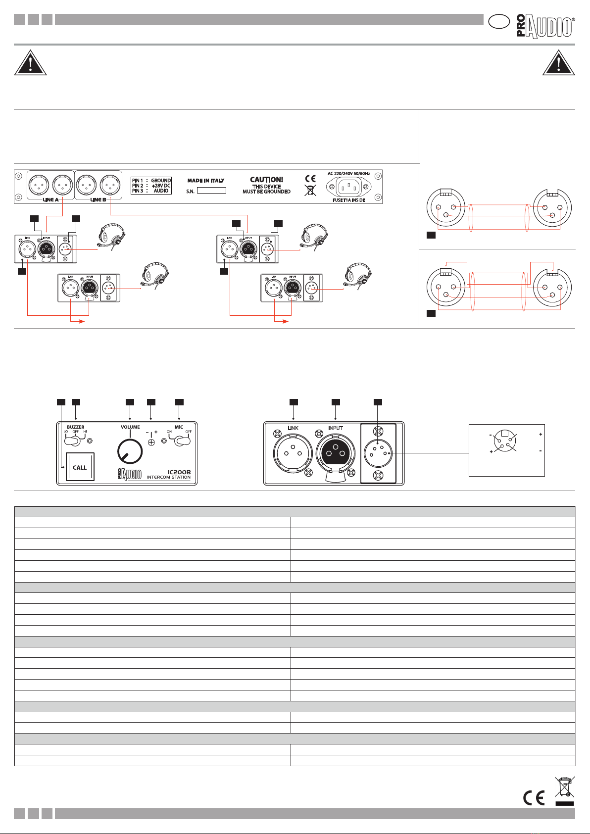
Connections and controls
The female 3 pin XLR3 connector INPUT (1) must be connected to the power supply unit, to the master station or to the
male 3 pin XLR3 connector LINK (2) of another remote station. The headset must be connected to the 4 pin male XLR4
connector (3) . The stations are designed for use with low impedance (600 Ωnominal) unbalanced dynamic micro-
phones and high impedance (100 ÷ 1000 Ω) unbalanced headphones.
For connection to the remote stations, it’s possible
to use standard microphone cables (2 conductors +
screen)(9) , in case of very long connections we strong-
ly suggest to use a 3 conductors + screen cable, having
at least 0.18 mm2 conductors, using the third conduc-
tor to connect the XLR connector’s body (frame) (10).
Max cable length may be more than 500 m, if cables
with large conductors and good screening are used.
General
Line impedance 220 Ω (audio) – 4700 Ω (dc)
Nominal line level -17 dBm
Max line level +4 dBm
Supply voltage range 15÷30 V dc, 28 V dc nominal, 36 V dc max
Current drain (at 28 Vdc) 18 mA typ. when operating, 50 mA max when calling
Station input impedance 18 kΩ (equivalent, bridging the intercom line)
Microphone preamplier
Frequency response 150 Hz ÷ 13 kHz (contoured for a better intelligibility)
Imput impedance 1 kΩ (to be used with 200 Ω ÷ 1 kΩ dynamic microphones)
Gain 29 dB
Maximum input level -30dBm
Headphones amplier
Frequency response 150 Hz ÷ 18 kHz (± 2 dB)
Gain +40 dB
Maximum output level +20 dBm (with 1 kΩ load)
Load impedance 200Ω ÷ 1000 Ω headphones, 32 Ω minimum
SIDE TONE adjustment range ± 20 dB, - 60 dB minimum at center position
Call circuit
Nominal call voltage + 12 V dc on audio line
Call detector sensitivity + 2 V d.c.
Dimenasions, weight and accessories
Dimensions and weight 90 x 42 x 108 mm (l x h x d) (excluding the belt clip). 370 g
Supplied accessories Nylon belt clip (removable for table-top mounting)
Technical specications
ICH01 o ICH02
headset
11
2 2
33
The MIC on/o switch (4) allows the microphone to be switched on and o. It is suggested to switch the microphone o, if not used, to reduce unwanted noise in the intercom
line. The green LED is lighted when the microphone is on. The rotary VOLUME control (6) adjust headphones listening volume. The screwdriver adjustable SIDE TONE trimmer
(7) adjust the level of the local microphone returned to the station’ s headphones. This control does not aect the microphone signal sent to other stations. In the center position
the microphone level (return) is kept to a minimum, but if the control is rotated clockwise or counterclockwise the microphone signal is returned to the headphones amplifier
with adjustable level and phase. Some users prefer to hear their own microphone’s signal for being sure that it’s operating. By pressing the CALL button (4) a call signal is sent to
all the stations connected to the same intercom line. The CALL lamp on these station ashes. The BUZZER switch (5), when set to the LO and HI position, enables the acoustic call
signaling, and adjusts the buzzer volume, to low (LO) or high (HI) level. If the buzzer is on, the yellow LED is lighted. In the OFF switch position, the buzzer is disabled.
4 5 6 7 8 2 1 3
1
23
4
XLR 4P F
( soldering side )
MIC.
MIC.
PHONES
PHONES
92 conductors + screen wired cable.
( Microphonic standard cable ).
10 3 conductors + screen wired cable.
( Suggested for very long connections ).
XLR 3P M XLR 3P F
241
3
142
3
(1) GROUND (screen)
(2) SUPPLY
(4) FRAME
(3) AUDIO
2 1
3
1 2
3
(1) GROUND (screen)
(2) SUPPLY
(3) AUDIO
XLR 3P M XLR 3P F
For further information, please contact our Service Center: tel. +39 0771 72190 fax +39 0771 721955 - ser[email protected]
Other manuals for INTERCOM 200 series
1
This manual suits for next models
1
Table of contents
Languages:
Other ProAudio Recording Equipment manuals