Version 04.05.2017 VL3-MBN51
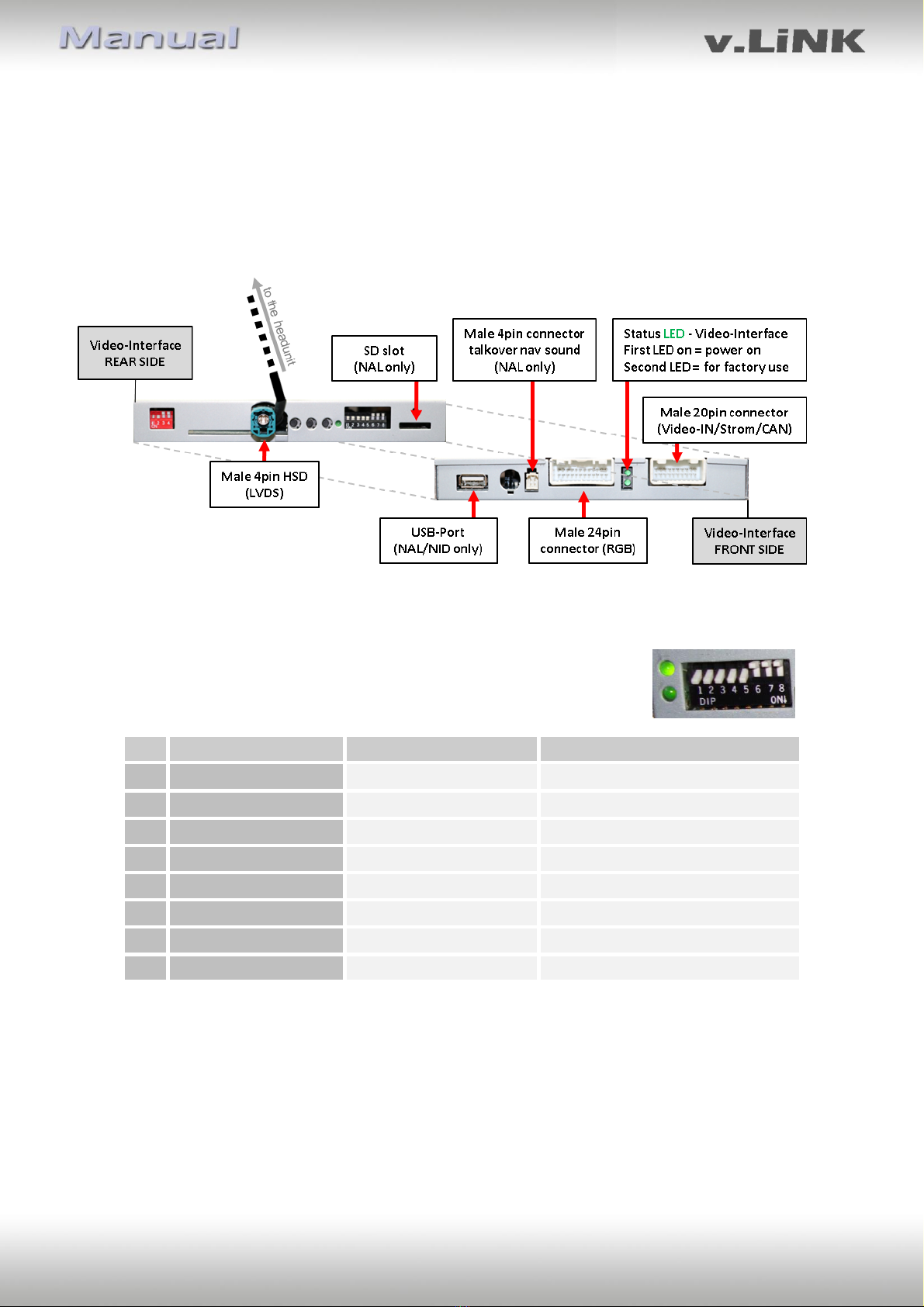
1.4.1. Enabling the interface’s video inputs (dip 1-3)
Only the enabled video inputs can be accessed when switching through the interface’s video
sources. It`s recommended to enable only the required inputs for the disabled will be
skipped when switching through the video-interfaces inputs.
1.4.2. RGB-video input signal selection for after-market navigation (Dip 4)
If an after-market RGB navigation or other RGB video source is connected, the source’s RGB
output signal must match the interface’s RGB video input setting.
1.4.3. Rear-view camera setting (dip 5)
If set to OFF, the interface switches to factory LVDS picture while the reverse gear is engaged
to display factory rear-view camera or factory optical park system picture.
If set to ON, the interface switches to its rear-view camera input “Camera-IN” while the
reverse gear is engaged.
1.4.4. Monitor selection (dip 8)
Dip 8 customizes the monitor-specific video settings. The “ON” position corresponds to the
7” monitor, while the “OFF” position belongs to the 8.4” monitor. If the right picture still
doesn’t appear after changing the dip switch, retry and after each dip switch change
disconnect the Power supply for a few seconds (Power-reset).
1.5. Dip-switch settings of the CAN-BUS
Dip position down is ON and position up is OFF.
2. Installation
Switch off the ignition and disconnect the vehicle’s battery! The interface needs a
permanent 12V source. If -according to factory rules- a disconnection of the battery has to
be avoided, it should be sufficient to use the vehicle’s sleep-mode. In case, the sleep-mode
doesn’t succeed, the battery has to be disconnected with a resistor lead.
The Interface needs a permanent power supply! If power isn’t directly taken from the
battery, the connection’s power has to be checked for being start-up proven and
permanent.
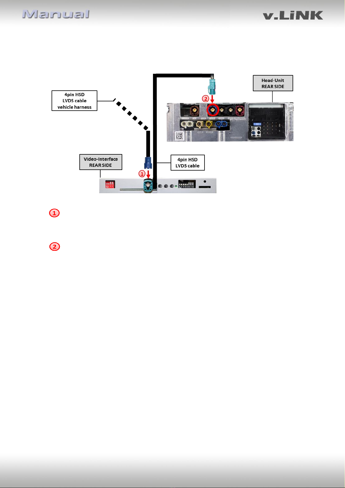
2.1. Place of installation: The interface is installed on the backside of the head-unit.