Procentec ProfiHub B5 Plus User manual

ProfiHub B5+ / B5+RD User Manual
_______________________________________________
Version 2.0 – July 2014 Page 1 / 56
ProfiHub-B5-Plus-Manual-EN.docx © PROCENTEC 2014 - Copyright - all rights reserved
User Manual
ProfiHub B5+ / B5+RD
5 Channel DP Spur and Repeater component
with Redundancy and optional Diagnostics Device
Integrated Diagnostics Device (on type B5+RD)
5 Isolated outgoing Channels.
Transparent for all PROFIBUS DP protocols.
RS 485 specifications for each channel.
Cable Redundancy
Max. 12 Mbps.
Max. 31 devices per channel.
Max. 1200 m spur line length.
No limit in serial placement.
Integrated termination facilities.
Configurable grounding system.
IP 20 classification.
Extended temperature range.
UL and DNV approved

ProfiHub B5+ / B5+RD User Manual
_______________________________________________
Version 2.0 – July 2014 Page 2 / 56
ProfiHub-B5-Plus-Manual-EN.docx © PROCENTEC 2014 - Copyright - all rights reserved
Safety Guidelines
This manual contains notices which you should observe to ensure your own personal safety, as well
as to protect the product and connected equipment. These notices are highlighted in the manual by a
warning sign and are marked as follows according to the level of danger:
Draws your attention to important information on handling the product, a particular part of the
documentation or the correct functioning of the product.
Warning
This device and its components may only be used for the applications described in this manual and
only in connection with devices or components that comply with PROFIBUS and an RS 485 interface.
This product can only function correctly and safely if it is transported, stored, set up, installed,
operated and maintained as recommended.
Qualified Technicians
Only qualified technicians should be allowed to install and work with this equipment. Qualified
technicians are defined as persons who are authorized to commission, to ground, to tag circuits and
systems in accordance with established safety practices and standards. It is recommended that the
technicians carry a Certified PROFIBUS Installer or Certified PROFIBUS Engineer certificate.
Disclaimer of Liability
We have checked the contents of this manual as much as possible. Since deviations cannot be
precluded entirely, we cannot guarantee full agreement. However, the content in this manual is
reviewed regularly and any necessary corrections included in subsequent editions. Suggestions for
improvement are welcomed.
Copyright © 2014 PROCENTEC
All rights reserved. No part of this publication may be reproduced, stored in a retrieval system, or
transmitted, in any form or by any means, electronic, mechanical, photocopying, recording or
otherwise, without the prior written permission of the publisher.
PROCENTEC
Klopperman 16
2292 JD WATERINGEN
The Netherlands
Tel.: +31-(0)174-671800
Fax: +31-(0)174-671801
Web: www.procentec.com

ProfiHub B5+ / B5+RD User Manual
_______________________________________________
Version 2.0 – July 2014 Page 3 / 56
ProfiHub-B5-Plus-Manual-EN.docx © PROCENTEC 2014 - Copyright - all rights reserved
Important Information
Purpose of the Manual
This manual explains how to put the ProfiHub B5+ into operation.
Recycling and Disposal
The parts of the ProfiHub can be recycled. For further information about environment-friendly recycling
and the procedure for disposing your old equipment, please contact:
PROCENTEC
Klopperman 16
2292 JD WATERINGEN
The Netherlands
Tel.: +31-(0)174-671800
Fax: +31-(0)174-671801
Document Updates
You can obtain constantly updated information on PROCENTEC products on the Internet at
www.procentec.com
You can also contact PROCENTEC Customer Support:
- by phone at +31-(0)174-671800
- by fax at +31-(0)174-671801

ProfiHub B5+ / B5+RD User Manual
_______________________________________________
Version 2.0 – July 2014 Page 4 / 56
ProfiHub-B5-Plus-Manual-EN.docx © PROCENTEC 2014 - Copyright - all rights reserved
Important Notices
WARNING
When the product is in use at an ambient temperature of 63 degrees Celsius or 145 degrees
Fahrenheit, the housing of the ProfiHub B5+ will be hot. Do not touch the housing!
At normal operating temperatures of 25 degrees Celsius, the temperature of the housing will not
exceed 35 degrees Celsius.
WARNING
When the product is in use at an ambient temperature of 63 degrees Celsius or 145 degrees
Fahrenheit, the housing of the ProfiHub B5+ will be hot. Do not touch wires which are in contact
with the housing!
WARNING
When the product is in use at an ambient temperature of 63 degrees Celsius or 145 degrees
Fahrenheit, the housing of the ProfiHub B5+ will be hot. Use wires suitable for these temperatures!
HOT HOUSING warning located on the side of the housing. Make sure this warning is visible after wall
installation. UL certification demands the warning to be visible during operation.
To comply with UL certification regulations (UL60950-1) the power supply must be a Limited Power
Source (LPS) or NEC Class 2 or CEC Class 2 that cannot exceed 100VA.
According to UL60950-1, if a copper PROFIBUS cable is used outside, it is required to install surge
protection that is suitable for PROFIBUS.
To comply with UL certification regulations the ProfiHub B5+ is to be used on altitudes under 2000 m.

ProfiHub B5+ / B5+RD User Manual
_______________________________________________
Version 2.0 – July 2014 Page 5 / 56
ProfiHub-B5-Plus-Manual-EN.docx © PROCENTEC 2014 - Copyright - all rights reserved
Contents
Important Notices .................................................................................................................................. 4
1Product Description...................................................................................................................... 7
1.1Product Features.................................................................................................................... 8
1.2Application areas.................................................................................................................... 9
1.3Additional Benefits ................................................................................................................. 9
1.4Channel Structure ................................................................................................................ 10
1.5Grounding System ............................................................................................................... 10
1.6Cable lengths for PROFIBUS DP ........................................................................................ 11
1.7Cable types for PROFIBUS DP............................................................................................ 12
1.8Status LEDs ......................................................................................................................... 13
1.9Comparison table ................................................................................................................. 14
2Installation Instructions ProfiHub B5+ ..................................................................................... 15
2.1Location................................................................................................................................ 15
2.2Position................................................................................................................................. 15
2.3Mounting............................................................................................................................... 15
2.4Power Supply ....................................................................................................................... 16
2.5Grounding of the power........................................................................................................ 17
2.6Relay contact ....................................................................................................................... 18
2.7Backbone ............................................................................................................................. 18
2.8Spur Segments .................................................................................................................... 19
2.9Termination .......................................................................................................................... 20
2.10Baudrate switch.................................................................................................................... 21
2.11Channel Redundancy........................................................................................................... 22
3Diagnostics Device..................................................................................................................... 23
3.1Setting up the Diagnostics Device ....................................................................................... 24
3.1.1Enabling the Diagnostics Device ..................................................................................... 24
3.1.2Changing the default PROFIBUS address ...................................................................... 24
3.1.3GSD file............................................................................................................................ 25
3.2Configuring the Diagnostic Device....................................................................................... 25
3.2.1Info data (mandatory module).......................................................................................... 25
3.2.2Alarm Confirmation .......................................................................................................... 25
3.2.3Redundant Status ............................................................................................................ 25
3.2.4Baudrate Status ............................................................................................................... 26
3.2.5Relay Status..................................................................................................................... 26
3.2.6Power Status.................................................................................................................... 26
3.2.7Termination Status........................................................................................................... 27
3.2.8Channel Status ................................................................................................................ 27
3.2.9Livelist Status................................................................................................................... 27
3.2.10Statistics (Short Format, Long Format ........................................................................ 28
3.3Parameterizing the Diagnostic Device ................................................................................. 30
3.3.1Diagnostics ...................................................................................................................... 30
3.3.2Statistics........................................................................................................................... 31
3.3.3Extended Diagnostics on Events change ........................................................................ 31
3.3.4Extended Diagnostics on Statistics change..................................................................... 32
3.3.5Alarm Relay on Events change ....................................................................................... 33
3.3.6Alarm relay on Statistics change ..................................................................................... 33
3.3.7Changing the Diagnostics duration/timeout..................................................................... 34
3.3.8Changing the Device Lost timeout................................................................................... 34
3.3.9Changing the data format ................................................................................................ 35
3.4ProfiTrace plugin for the Diagnostic Device......................................................................... 35

ProfiHub B5+ / B5+RD User Manual
_______________________________________________
Version 2.0 – July 2014 Page 6 / 56
ProfiHub-B5-Plus-Manual-EN.docx © PROCENTEC 2014 - Copyright - all rights reserved
3.4.1Installing the Plugin.......................................................................................................... 35
3.4.2Using the Plugin............................................................................................................... 36
4Technical Data ProfiHub B5+ / B5+RD...................................................................................... 37
5Sales offices and Distributors ................................................................................................... 39
6Order codes................................................................................................................................. 42
7Glossary....................................................................................................................................... 43
8Certificates .................................................................................................................................. 46
9Revision History.......................................................................................................................... 53
10Notes ............................................................................................................................................ 54
ProfiHub B5+ / B5+RD User Manual
_______________________________________________
Version 2.0 – July 2014 Page 7 / 56
ProfiHub-B5-Plus-Manual-EN.docx © PROCENTEC 2014 - Copyright - all rights reserved
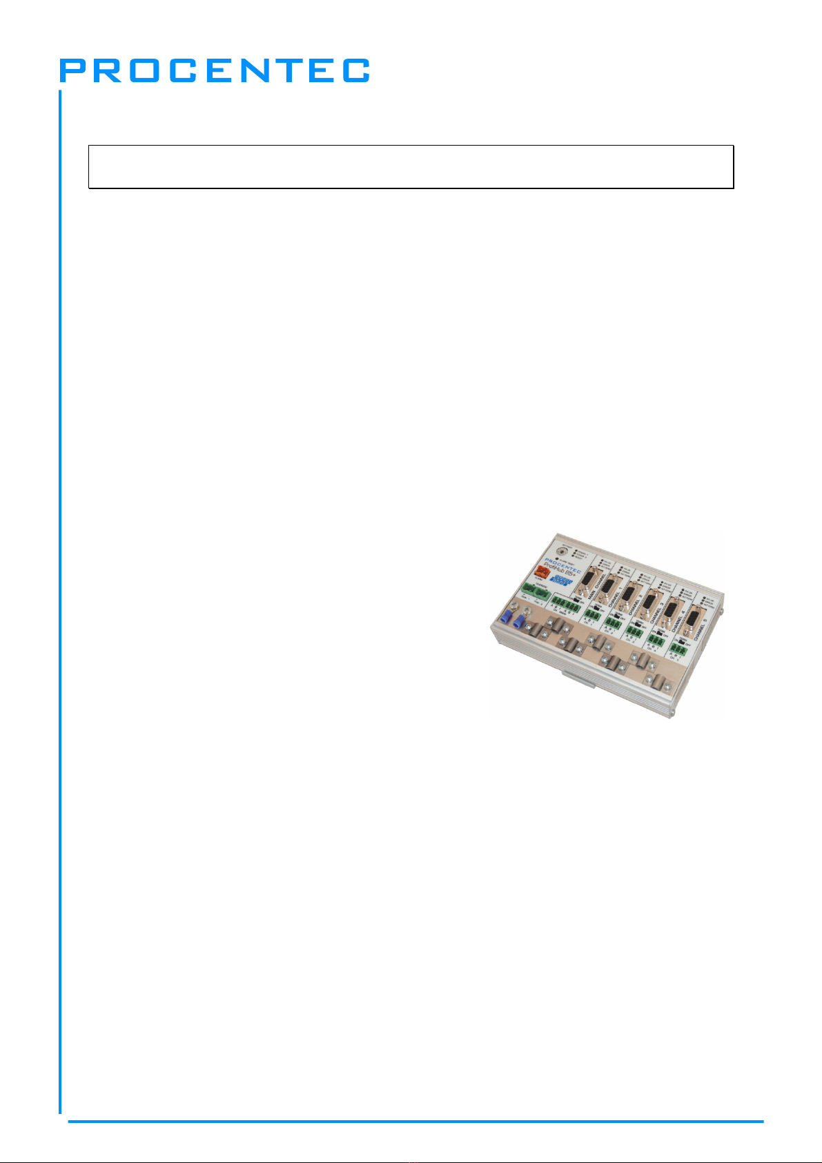
1 Product Description
ProfiHub B5+ is an advanced, flexible and robust network component for PROFIBUS DP
installations, to create backbone structures and long multi-device star/tree segments.
PROFIBUS DP is a high speed communication bus that must comply with strict rules concerning spur
lines, because of possible reflections that could lead to communication disturbances. If spur lines or
star segments are required, costly investments in repeaters have to be done.
The innovative ProfiHub B5+ is the perfect component for such applications. It is an economic solution
to realise reliable spur lines in high speed DP networks. They have the functionality of 5 galvanic
isolated transparent repeaters. This allows network structures with extended spur lines that
individually can handle a maximum of 31 devices and a length equal to the main bus. The ProfiHub
B5+ refreshes a received message on one Channel and transfers it to all the other Channels
(chicken foot topology).
Because the ProfiHub B5+ creates isolated segments, the devices can now be removed and added
during operation. Also most electrical bus problems and EMC disturbances in a spur do not spread to
the other segments. The intelligent logic and isolation circuits of the ProfiHubs do not change the bit
width. This means the ProfiHubs do not have limitations in serial placement. The logic also detects the
transmission speed automatically.
To assist the installation work, termination is integrated and
can be switched on/off. The grounding concept is also
selectable: direct or capacitive grounding. The ProfiHubs are
powered by a 10 to 24 DC Voltage. For troubleshooting,
maintenance and commissioning the ProfiHubs are equipped
with LEDs on the outside, which indicate the status of each
Channel (Data and Error).
If bus redundancy is enabled, 2 segments will form a
redundant pair which is completely compatible with the ABB
RLM01. An alarm contact is linked to events based on the
status of the power supply and the bus redundancy status.
Fig. 1 - ProfiHub B5+
ProfiHub B5+ / B5+RD User Manual
_______________________________________________
Version 2.0 – July 2014 Page 8 / 56
ProfiHub-B5-Plus-Manual-EN.docx © PROCENTEC 2014 - Copyright - all rights reserved
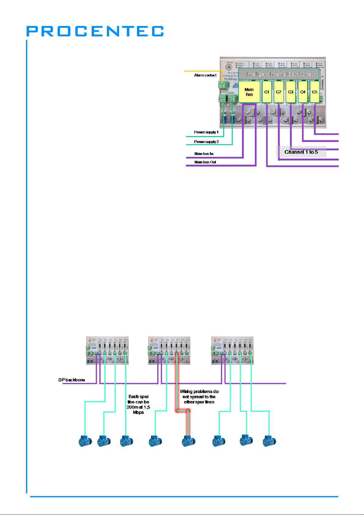
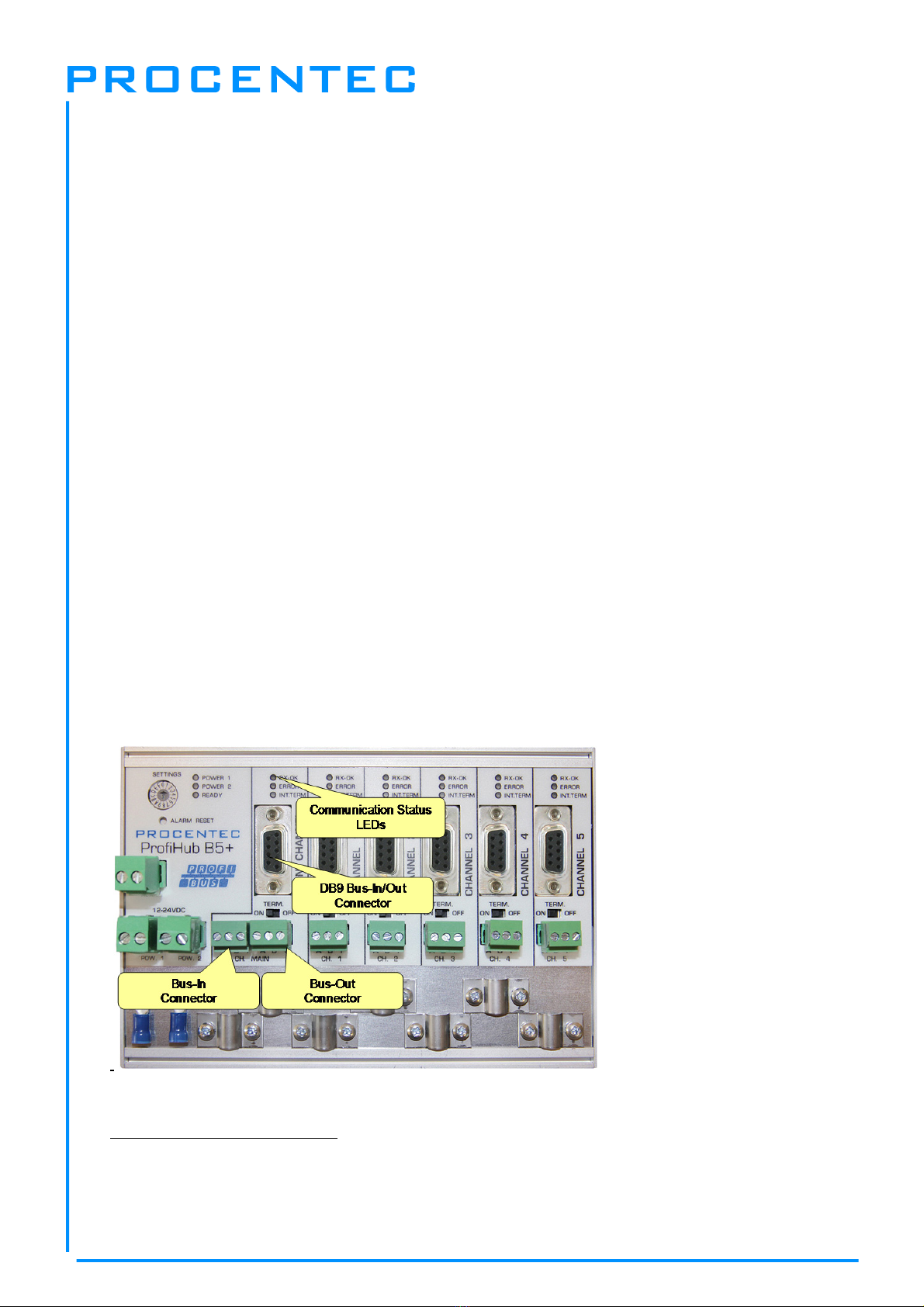
Fig. 2 - ProfiHub connections
1.1 Product Features
5 Galvanic isolated outgoing channels
(repeater segments).
Advanced Diagnostic capabilities (B5+RD)
Transparent for all PROFIBUS DP
protocols.
DP - RS 485 specifications for each
channel.
Cable redundancy for channel 4+5
9.6 Kbps to 12 Mbps.
31 devices per channel.
1200 m spur line length (depends on transmission speed).
Redundant power supply
No limit in serial placement or cascading of ProfiHubs.
Alarm contact, with manual reset button.
No address required (except for the B5+RD option).
Integrated termination facilities (switches).
Configurable grounding system (direct or capacitive).
IP 20 classification
Increased temperature range
DNV / offshore Certification
UL approvals
Fig. 3 - Long spur lines to instruments and the possibility to remove/insert them during operation. Short
circuit protection on each spur line is automatically provided.

ProfiHub B5+ / B5+RD User Manual
_______________________________________________
Version 2.0 – July 2014 Page 9 / 56
ProfiHub-B5-Plus-Manual-EN.docx © PROCENTEC 2014 - Copyright - all rights reserved
Noisy signalNoisy signal
Clean signalClean signal
1.2 Application areas
Dynamic spur lines to actuators, flow meters and pH analyzers.
Removable drives and motors.
Pull/Plug motor control centers (drawers).
Roof mounted devices in tank farms.
Barrier for non galvanic isolated equipment.
Networks with requirement for High Availability/uptime
Large star/tree structured networks.
1.3 Additional Benefits
Hot slave insertion and removal during operation.
Short circuit protection on each Channel.
Option to create a redundant path to other Hubs or COMbricks
Compact and robust construction.
Status and error display (per Channel).
Suitable for all DP cables.
Conveniently arranged networks.
Easy extendable installations.
On-board DB9 female connector on each channel for maintenance activities.
Cost Savings.
Fig. 4 - Because of the isolation and intelligence the ProfiHub provides, it can be used as a
barrier for electrically sensitive segments. This keeps the backbone and other Channels
clean.
ProfiHub B5+ / B5+RD User Manual
_______________________________________________
Version 2.0 – July 2014 Page 10 / 56
ProfiHub-B5-Plus-Manual-EN.docx © PROCENTEC 2014 - Copyright - all rights reserved
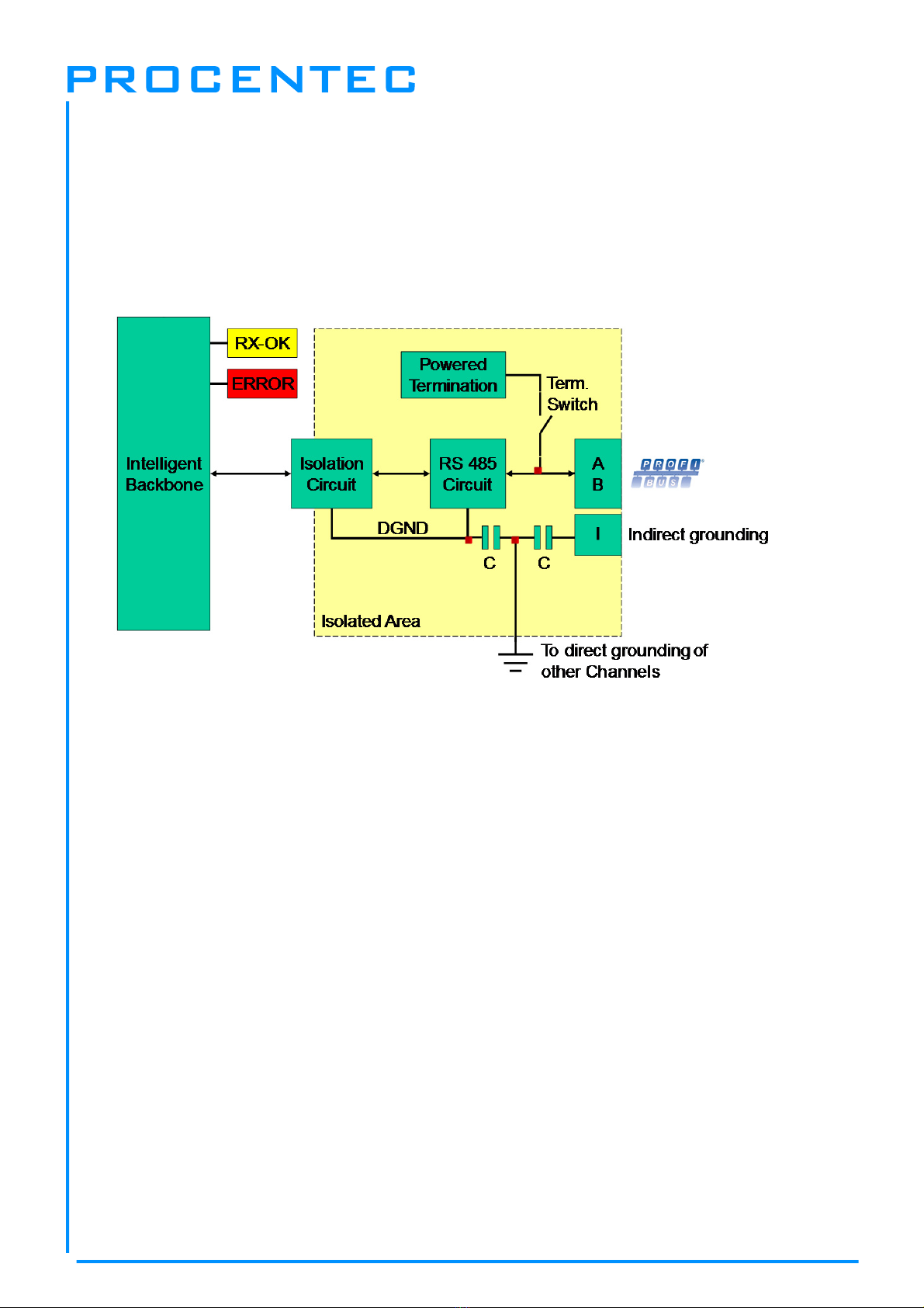
1.4 Channel Structure
Each Channel is electrically isolated and internally connected to the transparent intelligent backbone.
The termination is switchable and powered by the ProfiHub. The shielding of the PROFIBUS cable can
be directly grounded or indirectly grounded (see the next paragraph).
1.5 Grounding System
The ProfiHub B5+ can be grounded by 3 methods:
1) Direct grounding on the Ground Rail
2) Indirect grounding (through a capacitor)
3) Combination of direct and indirect.
The power supply must be grounded directly on the Ground Rail. The shielding of the PROFIBUS
cables can be directly or indirectly grounded. If you do not want to ground all or some cables to the
common ground, i.e. compensating current, the cable shielding must be connected to pin ‘I’ which
stands for Indirect grounding. A capacitor with a parallel high value resistor will separate the 2
potentials (
Fig. 5
), ensuring protection of the signal against non-DC disturbances.
If by accident on 1 channel the Direct Grounding is connected with the Indirect Grounding, the
connection to the Direct Grounding bypasses the capacitor in the Indirect Ground connection. The
current on the shield will flow to Direct Ground.
Fig. 5 - Channel structure

ProfiHub B5+ / B5+RD User Manual
_______________________________________________
Version 2.0 – July 2014 Page 11 / 56
ProfiHub-B5-Plus-Manual-EN.docx © PROCENTEC 2014 - Copyright - all rights reserved
Baudrate (kbit/s)
Segment length
(m)
9.6
1200 1200
19.2 1500 6000 120003000500187.593.7545.45
100100100200400100012001200
Segment length
(feet) 3940 3940 3283283286561310328039403940
Baudrate (kbit/s)
Segment length
(m)
9.6
1200 1200
19.2 1500 6000 120003000500187.593.7545.45
100100100200400100012001200
Segment length
(feet) 3940 3940 3283283286561310328039403940
Baudrate (kbit/s)
Segment length
(m)
9.6
1200 1200
19.2 1500 6000 120003000500187.593.7545.45
100100100200400100012001200
Segment length
(feet) 3940 3940 3283283286561310328039403940
DeviceDevice Device Device Device Device
Maximum 31 devices
Example: 1000 m cable per channel at 187,5 kbps
Other channels
With the same
Cable length
1.6 Cable lengths for PROFIBUS DP
The cables on the Channels and the Main-Channel must comply with the PROFIBUS DP cable
specifications for RS 485 (Fig. 6).
Fig. 6 - Cable lengths for PROFIBUS DP

ProfiHub B5+ / B5+RD User Manual
_______________________________________________
Version 2.0 – July 2014 Page 12 / 56
ProfiHub-B5-Plus-Manual-EN.docx © PROCENTEC 2014 - Copyright - all rights reserved
1.7 Cable types for PROFIBUS DP
The cable type must comply with the PROFIBUS DP cable specifications for RS 485 (Fig. 7).
The ProfiHub B5+ can handle cables based on multiple protection sheaths with an overall cable
diameter between 6 to 12 mm (Fig. 8).
Parameter Value
Wires 2 (twisted)
Impedance 135 .. 165 Ohm at 3 to 20 MHz
Capacity < 30 pF/m
Loop resistance < 110 Ohm/km
Wire diameter > 0.64 mm
Wire area > 0.32 mm2
FRNC cable
Shipboard cable
Festoon cable
Flexible cable
Food cable
Robust cable
Trailing cable
Hybrid cable
Fig. 7 - PROFIBUS DP cable specifications
Fig. 8 - Cables with different protection sheaths.

ProfiHub B5+ / B5+RD User Manual
_______________________________________________
Version 2.0 – July 2014 Page 13 / 56
ProfiHub-B5-Plus-Manual-EN.docx © PROCENTEC 2014 - Copyright - all rights reserved
1.8 Status LEDs
The Status LEDs on the ProfiHub are very useful for diagnostics.
OFF Blinking ON
POWER 1 / 2 Power is not
switched on or an
internal failure.
Power supply not
stable, redundant power
supply interrupted or an
internal failure.
Power supply OK.
READY Power is not
switched on or an
internal failure.
Trying to detect the
transmission speed, but
has not locked it yet.
The transmission
speed has been
detected.
Main RX-OK No communication
detected on the Main-
Channel.
1 or more devices
communicating on the
Main-Channel.
1 or more devices
communicating on the
Main-Channel.
Main ERROR No problem has
been detected.
Problem in the
cabling has been
detected (Main
Channel).
Problem in the
cabling has been
detected (Main
Channel).
Channel RX-OK There is no
communication
detected (on this
Channel).
1 or more devices
communicating (on this
Channel).
1 or more devices
communicating (on this
Channel).
Channel ERROR No problem has
been detected.
Problem in the
cabling has been
detected (on this
Channel).
Problem in the
cabling has been
detected (on this
Channel).
INT. TERM Termination for this
channel is OFF.
Internal failure. Termination for this
channel is ON.

ProfiHub B5+ / B5+RD User Manual
_______________________________________________
Version 2.0 – July 2014 Page 14 / 56
ProfiHub-B5-Plus-Manual-EN.docx © PROCENTEC 2014 - Copyright - all rights reserved
1.9 Comparison table
ProfiHub A5 ProfiHub B5 ProfiHub B5+ / B5+RD
Area IP 65 IP 20 IP 20
Redundant power
supply
No No Yes
Temperature range -20 to +60˚Celcius -20 to +60˚Celcius -25 to +70˚Celcius
Housing Plastic Metal Metal
Mounting Corner screws DIN-rail DIN-rail
Weight 800 g 650 g 650 g
Dimensions 213 x 210 x 95 mm 167 x 111 x 32 mm 167 x 111 x 32 mm
PROFIBUS connectors Screw terminals (inside)
Glands (outside)
Screw terminals and
DB9 connectors
Screw terminals and DB9
connectors
Alternative connectors Glands can be replaced
by M12 connectors
No No
Termination LEDs No Yes Yes
Ground rail Optional Yes Yes
Redundant channel No No Yes
Diagnostics Device None None Yes, in B5+RD
Offshore approvals None None Yes
UL approvals None None Yes

ProfiHub B5+ / B5+RD User Manual
_______________________________________________
Version 2.0 – July 2014 Page 15 / 56
ProfiHub-B5-Plus-Manual-EN.docx © PROCENTEC 2014 - Copyright - all rights reserved
2 Installation Instructions ProfiHub B5+
2.1 Location
The ProfiHub B5+ can be installed everywhere in a non-hazardous area that complies with IP 20 (DIN
40 050) and the specified temperature range of -25 to +70o Celsius.
2.2 Position
The ProfiHub B5+ can be installed in every position, but it is recommended to install it with the cables
pointing down. In this position it is also easier to read the status LEDs.
2.3 Mounting
The ProfiHub B5+ can be mounted on 35 mm DIN-rail with a minimum width of 167 mm. Mounting
brackets are available for mounting the B5+ directly on a wall. The ProfiHub B5+ has only been UL
and DNV approved with 35 mm DIN-rail mounting!
The supplied rubber studs need to be placed on the back of the housing of the ProfiHub B5+ for extra
fixation. This is to prevent the product to potentially slide off the DIN-rail. See
Fig. 9
for an example.
When used in DNV environments these rubber studs need to be installed!
Fig. 9
–
Rubber studs on backside of housing
ProfiHub B5+ / B5+RD User Manual
_______________________________________________
Version 2.0 – July 2014 Page 16 / 56
ProfiHub-B5-Plus-Manual-EN.docx © PROCENTEC 2014 - Copyright - all rights reserved
2.4 Power Supply
To comply with UL certification regulations the power supply must be a Limited Power Source (LPS) or
NEC Class 2 or CEC Class 2 that cannot exceed 100VA.
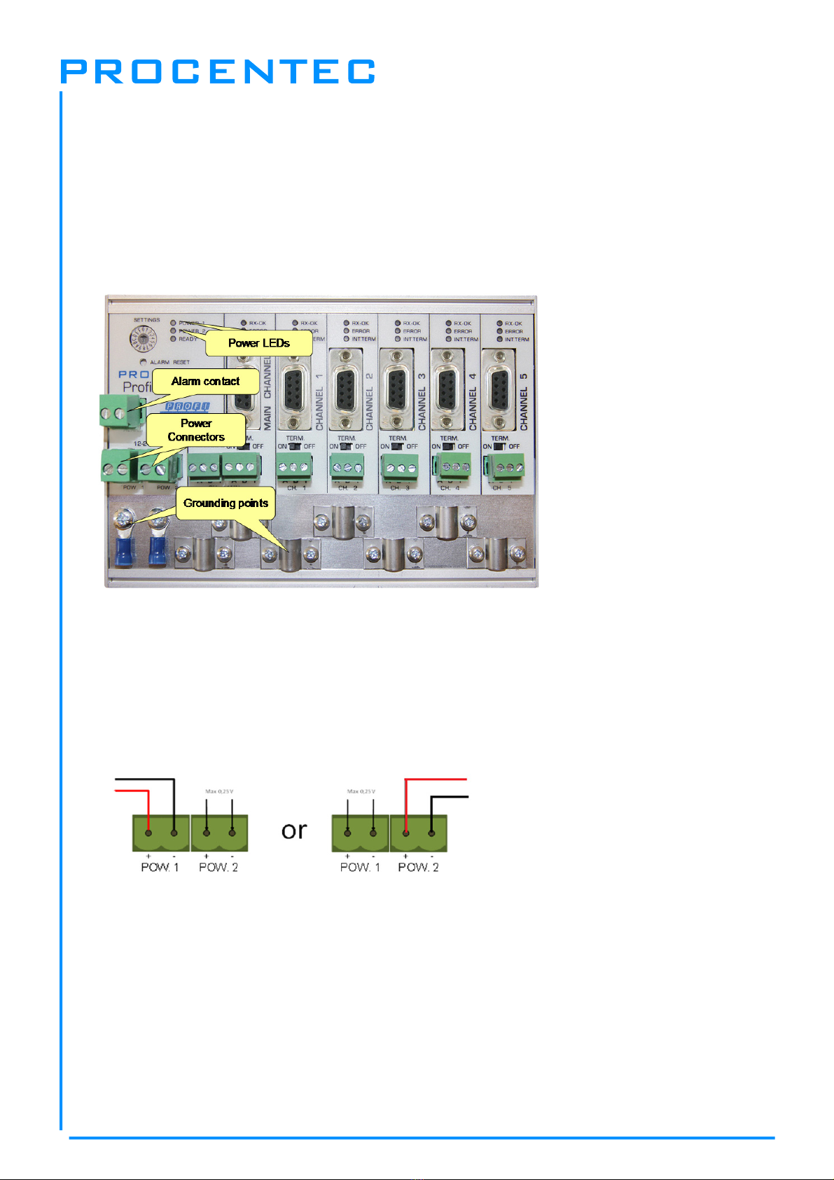
The two 2-pin screw type power connectors are located on the left of the ProfiHub B5+ (
Fig. 10
).
1 = +(left)
2 = -(right)
Both power connectors are linked 1-on-1 to the internal power supply of the B5+. If one power supply
fails, the other takes over without delay time. When redundancy is not required, it is sufficient to use
one power connector. Please note that when using only one power supply, a voltage of max. 0.25 V
will exist on the other unconnected power connector, as shown in
Fig. 11
.
If only one power supply is used, the alarm contact is closed. If two power sources are connected, the
contact is open. As soon as one of the power supplies fails, the contact will close and the Power
Indicator LED will blink.
For UL certified installations the power supply must comply with the following specifications:
- Limited Power Source (LPS) or NEC Class 2 or CEC Class 2
- Voltage: 12 - 24 VDC
- Current: min 275 mA
- Wire diameter: < 2.5 mm2
Fig. 10 - Power connecto
r
s and LEDs
Fig. 11
–
Maximum voltage on unconnected Power Connecto
r

ProfiHub B5+ / B5+RD User Manual
_______________________________________________
Version 2.0 – July 2014 Page 17 / 56
ProfiHub-B5-Plus-Manual-EN.docx © PROCENTEC 2014 - Copyright - all rights reserved
Procedure
To connect the 24V supply to the 2-pin screw-type terminal, proceed as follows:
- Strip the insulation from the cable or the conductors for the 24V power supply.
- Add cable crimp terminals/wire ferrules to the conductors.
- Secure the crimp terminals in the screw-type terminal.
To connect the power supply, you need a 3 mm screwdriver.
Testing
If the power is switched on it can be diagnosed by the following indicators:
- LEDs should be blinking in a circular animation for a short time.
- The POWER LED of the respective power connector (1, 2 or both) is ON.
- The READY LED is ON or Blinking, depending on baud rate lock.
2.5 Grounding of the power
It is recommended to use a power supply with a ground lead (3-wire). Connect the ground
lead of the power lead to the Ground Rail of the ProfiHub B5+. Connect the Ground Rail to the
common ground with a separate ground lead. See Fig. 12 for an example.
Fig. 12 - Connection to Ground Rail
ProfiHub B5+ / B5+RD User Manual
_______________________________________________
Version 2.0 – July 2014 Page 18 / 56
ProfiHub-B5-Plus-Manual-EN.docx © PROCENTEC 2014 - Copyright - all rights reserved
2.6 Relay contact
The ProfiHub B5+ features a potential-free relay contact. This alarm contact can be used to monitor
the power supplies. Example applications are: Connect a LED tower, alarm buzzer, SMS server or use
it as a digital signal for the PLC. On the B5+RD version the relay can also be used for alarming in case
of retires, illegals, or other events. For more information refer to Chapter 3.
If only one power supply is used, the alarm contact is closed after 60 seconds after start-up. If two
power sources are connected, the contact is open. When one of the power supplies fails for 3 seconds
or more, the contact will close and the Power Indicator LED will blink. If you are using only one power
source and wish to use the Relay contact, simply connect Power 1 to Power 2.
In the case of an interrupted power supply you can reset the contact by pressing the ‘Reset’ button.
The contact will open and the LEDs will stop blinking.
The Alarm contact is also switched when the ProfiHub is in Redundant mode and one of the redundant
paths fails.
The maximum power to be connected to the alarm contact is 24 VDC. The maximum current
consumption is 500 mA.
It is advised to use a Limited Power Source (LPS) of NEC Class 2 or CEC Class 2 for powering the
alarm contact.
2.7 Backbone
Connect the DP backbone cable to the bottom-left connector of the Main-Channel (
Fig. 13
). If the
ProfiHub is not the last device on the bus segment, connect the Bus-Out cable to the right connector
of the Main-Channel (
Fig. 13
). The second method is to place a PROFIBUS standardized plug with an
in/out cable on the DB9 connector.
Pin layout of the screw terminals:
Pin “A”: Green wire
Pin “B”: Red wire
Pin “I”: Indirect cable shielding
Fig. 13 - PROFIBUS DP backbone connection

ProfiHub B5+ / B5+RD User Manual
_______________________________________________
Version 2.0 – July 2014 Page 19 / 56
ProfiHub-B5-Plus-Manual-EN.docx © PROCENTEC 2014 - Copyright - all rights reserved
Note: Connecting the Indirect cable shielding is not required when the ground clips are used.
Testing
- If the Main-Channel recognizes valid PROFIBUS messages from one or more connected devices,
the RX-OK LED of the Main Channel should be blinking.
2.8 Spur Segments
Connect the spur segments to the connectors of Channel 1 to 5 (
Fig. 14
). The second method is to
place a PROFIBUS standardized plug on the DB9 connector of the specific Channel.
Pin layout of the screw terminals:
Pin “A”: Green wire
Pin “B”: Red wire
Pin “I”: Indirect cable shielding
Note: Connecting the Indirect cable shielding is not required when the ground clips are used.
Testing
- If a Channel recognizes valid PROFIBUS messages from one or more connected devices, the RX-
OK LED of the Channel should be blinking.
According to UL60950-1, if a copper PROFIBUS cable is used outside, it is required to install surge
protection that is suitable for PROFIBUS.
Fig. 14 - PROFIBUS DP spur connectors

ProfiHub B5+ / B5+RD User Manual
_______________________________________________
Version 2.0 – July 2014 Page 20 / 56
ProfiHub-B5-Plus-Manual-EN.docx © PROCENTEC 2014 - Copyright - all rights reserved
2.9 Termination
The termination of the Main-Channel has been set to OFF by default. If the ProfiHub is the last device
on the segment, the termination must be set to ON (
Fig. 15
).
The termination of the Channels have been set to ON by default, because it is assumed that the new
segment is started at the ProfiHub (
Fig. 15
).
The termination LED of the corresponding Channel is activated when the termination switch is set to
ON.
When the DB9 connector is used and the cable starts at the ProfiHub, it is recommended to
use the termination on the DB9 plug and NOT the ProfiHub. This way, the connector can be removed
while maintaining termination on the bus.
Fig. 15 - Te
r
mination Switches
Table of contents


