PVI Vecoax Compact RF Series User manual

VECOAX COMPACT RF SERIES MODULATOR
MANUAL
USER MANUAL

Pro Video Instruments
VeCOAX Compact RF Series Modulator Manual
1
VECOAX COMPACT RF SERIES MANUAL
PRODUCT SPECS & FEATURES
Power - 12v/DC (12v/1A)
All Major TV Encoder standards build-in. No need to reprogram or flash the unit to a different Format.
QAM (J.83B Digital Cable), ATSC (Digital Over the Air Channels), ISDBTb, DVBT, DVB-C, DMBT Set via
Color Display
Compact Design makes installation easy.
Works with most TV brands, including Samsung, Sony, Vizio, LG, and More.
Receives on TVs as its own HDTV channel as a FULL HD signal Up to 1080P with Dolby Digital Audio
(AC3)
Easy Plug and Play Setup with customization options available in the easy to use menu via a Color
Display.
Can be controlled Via Computer USB port on the unit with a custom application specifically made for
the Unit.*(Option May Vary Depending on Model)
Works With any HD Video HDMI source.*(720P or 1080P/I Fixed Resolution)
Can be mixed with other HDTV signals such as Digital Cable or Over the Air Channels* (depending on
Frequencies available for you to use)
Modular –Expandable –Reliable - 5 Year Warranty - Affordable

Pro Video Instruments
VeCOAX Compact RF Series Modulator Manual
2
NOTE: BEFORE INSTALLATION
Please test each unit UNMOUNTED ON A TEST BENCH with your Test TV before installing your units to
ensure you are receiving the Test Pattern signal. Then Program your unit. If installing Multiple units,
make sure each unit has its own frequency it's broadcasting on as well as it’s own Major/Minor.
This makes troubleshooting easier.
To test your unit, simply connect your TV with a short piece of Coax cable to the RF out of the Unit. No
HDMI needs to be connected for this test.
Scan for channels on the connected TV. Depending on your supported TV standards, scan for digital
channels.
After the scan is complete, you can tune to channel 1.1, and the test pattern will be visible.
By default, our unit is set to QAM (J.83B Cable) mode. This can be changed by referring to our QUICK
GUIDE below.
Please refer below for our QUICK GUIDE to setting up your device for your application and needs.
NOTE: IF YOUR TV TUNER HAS DIFFICULTY PICKING UP THE CHANNEL PLEASE REFER TO
OUR ADVANCED MENU -> MIXER MODE OPTION AS WELL AS ENSURING YOUR TV
STANDARD IS SET UP FOR YOUR TV TUNER’S SUPPORTED FORMAT, SUCH AS DIGITAL CABLE
OR DIGITAL ATSC. THIS MIXER MODE IS INCLUDED IN SOFTWARE VERSION VECOAX 2.37
AND ABOVE

Pro Video Instruments
VeCOAX Compact RF Series Modulator Manual
3
FIRST TIME INSTALLING? –
Please see our quick setup guide below.
INSTALLING MULTIPLE UNITS? –
Please see page 13 “Installing Multiple Units”. Each unit MUST have its own frequency and major
channel number.
QUESTIONS ABOUT THE DIFFERENT STANDARDS? -
Check out our explanation of each standard below. Please refer to your TV manual for the supported
Tuner Formats such as Digital ATSC or Digital QAM J.83B cable
WHAT IS THE ADVANCED MENU? –
The Advanced Menu allows adjustments of PSIP and other tweaks such as the Units RF strength.
Please look at page 12 for more info.
TRYING TO MIX SIGNAL WITH OTHER MODULATORS? –
Please ensure you don’t set our unit on the same frequency as your other modulators as well as
balancing the RF level. If you broadcast our unit on the same frequency as your other modulators it
will cancel each other out or cause unwanted results on your TV image such as two channels split on
one screen. Please see Page 13 for more info.
MIXING OVER THE AIR ATSC SIGNALS WITH OUR UNIT? –
Please see page 14 for more info.
NO AUDIO, OR POOR AUDIO? –
Please ensure your HDMI source audio is set to Stereo PCM or 2 Channel Audio. This is different for
every device. We want to ensure we feed uncompressed 2 channel audio, so the unit does not over
compress the audio which can lead to unwanted results over time. The unit will take care of the Dolby
Digital audio for you in QAM and ATSC standards.
TV WON’T PICK UP THE CHANNEL? –
Ensure you are using the correct Standard that is supported for your TV tuner. Refer to your TV spec
sheet for this information or the manual. If you have other Modulators or RF signals in your
distribution network, refer to pages 13-14.
OTHER ISSUES OR CONCERNS? –SEE THE TROUBLESHOOTING AND FAQ SECTIONS.

Pro Video Instruments
VeCOAX Compact RF Series Modulator Manual
4
QUICK SETUP GUIDE –USA/CANADA
1) It is recommended to test the device first on a test bench for your application before making it a
permanent installation to your system so troubleshooting is easier.
2) Connect your included Power adapter into the unit. Once the unit is powered on you will see the
main menu.
3) First, Connect a short piece of coax cable to your TV’s RF In and the other end to the unit’s RF
Out.
4) On the unit press the Enter button to enter the settings menu.
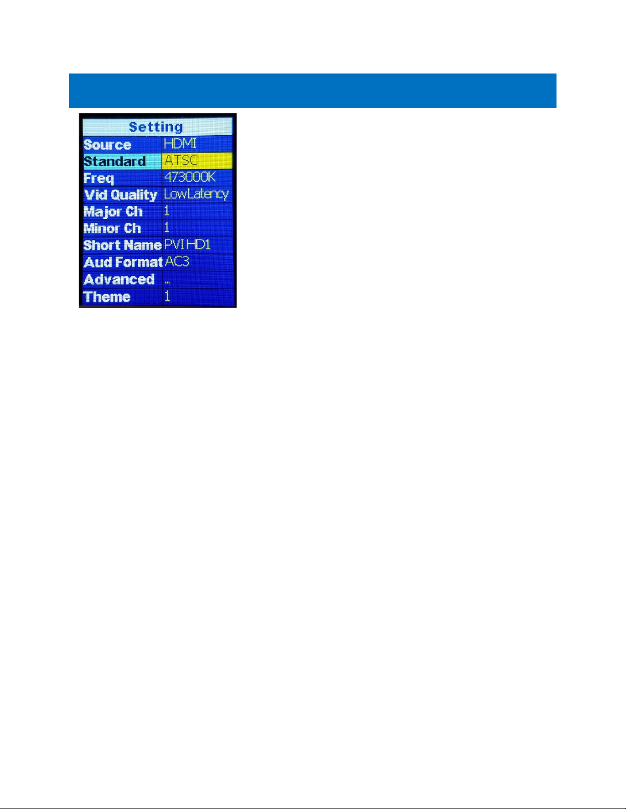
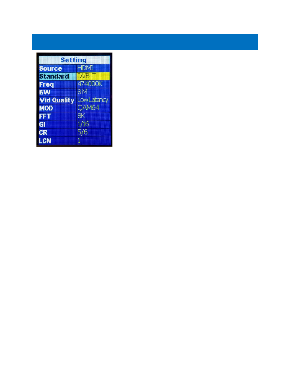
5) Set your TV Standard that you need to use. If you are unsure, most newer TVs 3 years and above
accept both ATSC (over the air channel) and QAM (J.83B Digital Cable).
6) By default, the unit is set to QAM (J.83B) Mode with a Frequency of 783.000 MHz which is
physical channel 122. The TV will pick up the channel on Cable and display our PVI logo when no
HDMI is connected.
7) Use the Major and Minor channels on the unit’s settings to change the channel number that is
displayed and stored on your TV. By default, the unit is set to output on channel 1.1: Major 1,
Minor 1.
8) Auto Scan for Channels on your TV. If needed, use the scan type that corresponds to the
Standard you set on the unit. (Cable or Digital Cable = J83B, Air or Antenna = ATSC, etc.)
9) Once the scan is complete, tune to the Channel found on your TV. You should see a PVI test
pattern screen.
10) Connect your HDMI source cable. Please ensure that your HDMI source such as a DVD player or
DirecTV STB is set to a Fixed Resolution of 1080P or 720P.
11) Once you have inserted a valid HDMI Video Signal into the HDMI port, the On-air LED on the
front will stay steady lit.
12) You should now see the video playing on your Channel.
13) If you wish to change the name of the channel that is displayed, you may do so under the Short
name settings of the unit. 4-6 Characters max is allowed depending on your TV.
14) More detailed information can be found under Parameters and Adjustments if additional
customization is required.
NOTE: If the above is not working, please check all connections, Units Settings, Correct TV Standard is
set for your TV, and ensure your video source is working or Set to a Correct Fixed Resolution. You
could also try with another TV with no HDMI connected to ensure you are getting a signal, or reset the
VeCoax unit by holding the ESCAPE button for until it prompts you to factory reset the unit. Press
enter to reset the unit’s settings to default. This may also be done in the Advanced Menu of the unit
called “RESET.” If the “ON-AIR,” LED does not stay steady, please ensure your HDMI source is set to a
fixed resolution of 1080P or 720P and connected directly to the Unit. If you are using a Splitter, some
splitters don’t support EDID pass-through (Extended Display Identification Data used to tell the source
or TV what video resolution is supported)

Pro Video Instruments
VeCOAX Compact RF Series Modulator Manual
5
PARAMETERS & CUSTOMIZATIONS
Each unit is ready to work plug and play by default. After connecting the unit using our Quick guide
above you may customize the settings, such as Frequency, Major and Minor channel numbers, Short
name, or TV standard.
If you are installing Multiple Units Please see page 13 “Installing Multiple Units” Each unit MUST have
its own frequency and major channel number.
Please ensure you don’t set our unit on the same frequency as your other modulators as well as
balancing the RF level. If you broadcast our unit on the same frequency as your other modulators it
will cancel each other out or cause unwanted results on your TV image such as two channels split on
one screen. Please see Page 14 for more information.

Pro Video Instruments
VeCOAX Compact RF Series Modulator Manual
6
QAM (J.83B DIGITAL CABLE)
These are the Defaults and Good
starting point for PLUG N PLAY
setup.
If you have more than one unit
please ensure you change the
FREQUENCY, MAJOR/MINOR, and
SHORT NAME so they don’t
overlap and create issues.
With the above default, the unit
outputs on 783 MHz as channel 1.1.
•SOURCE –Set your Video Source HDMI, CVBS, or SDI
depending on your model
•STANDARD –Set your TV standard depending on
your needs, location, and support format of your TV.
•FREQ –Set your Frequency using our QAM
Frequency chart starting on page 22. TVs will scan for
the Frequency, then store the channel as the
Major/Minor channel number you have set on the
Unit.
•VID QUALITY –Set the Latency Mode of your Video.
•MOD –Modulation Mode you wish to use. QAM64 is
the default and works with 99% of TVs
QAM256 is used in applications that require it such
as with other coax systems that use QAM256 or only
support QAM256 mode
•MAJOR CHANNEL –This is the Major channel
number that will be displayed and stored in the TV’s
Virtual Channel Table (VCT). (For example, for
channel “10.1”, “10” is the Major channel number.)
•MINOR CHANNEL –This is the Major channel
number that will be displayed and stored in the TV’s
Virtual Channel Table (VCT). (For example, for
channel “10.2”, “2” is the Minor channel number.) If
you wish to have many channels with the same
Major number, use the Minor number to
differentiate.
•SHORT NAME –Name of the Channel you wish to
use. 4-6 Characters max depending on TV.
•AUDIO FORMAT –Set your desired Audio Format.
AC3 is the Default Standard for ATSC and QAM
mode.
•ADVANCED –Advanced options for users who
require Specific PIDs or Fixed EDID information.
Please don’t change these unless you understand
your required PIDs or EDID per Cable Provider
instructions or PVI Tech Support request.

Pro Video Instruments
VeCOAX Compact RF Series Modulator Manual
7
ATSC (OVER THE AIR CHANNEL)
These are the Defaults and Good
starting point for PLUG N PLAY
setup.
If you have more than one unit
please ensure you change the
FREQUENCY, MAJOR/MINOR, and
SHORT NAME so they don’t
overlap and create issues.
With the above default, the unit
outputs on 473 MHz as channel 1.1.
•SOURCE –Set your Video Source HDMI, CVBS, or SDI
depending on your model
•STANDARD –Set your TV standard depending on
your needs, location, and support format of your TV.
•FREQ –Set your Frequency using our ATSC
Frequency chart starting on page 32. TVs will scan for
the Frequency, then store the channel as the
Major/Minor channel number you have set on the
Unit.
•VID QUALITY –Set the Latency Mode of your Video.
•MAJOR CHANNEL –This is the Major channel
number that will be displayed and stored in the TV’s
Virtual Channel Table (VCT). (For example, for
channel “10.1”, “10” is the Major channel number.)
•MINOR CHANNEL –This is the Major channel
number that will be displayed and stored in the TV’s
Virtual Channel Table (VCT). (For example, for
channel “10.2”, “2” is the Minor channel number.) If
you wish to have many channels with the same
Major number, use the Minor number to
differentiate.
•SHORT NAME –Name of the Channel you wish to
use. 4-6 Characters max depending on TV.
•AUDIO FORMAT –Set your desired Audio Format.
AC3 is the Default Standard for ATSC and QAM
mode.
•ADVANCED –Advanced options for users who
require Specific PID’s or Fixed EDID information.
Please don’t change these unless you understand
your required PIDs or EDID per Cable Provider
instructions or PVI Tech Support request.

Pro Video Instruments
VeCOAX Compact RF Series Modulator Manual
8
DVB-T GENERIC
These are the Defaults and Good
starting point for PLUG N PLAY
setup.
If you have more than one unit
please ensure you change the
FREQUENCY, LCN, and SHORT
NAME so they don’t overlap and
create issues.
•SOURCE –Set your Video Source HDMI, CVBS, or SDI
depending on your model
•STANDARD –Set your TV standard depending on
your needs, location, and support format of your TV.
•FREQ –Set your Frequency using our DVB-T
Frequency chart starting at page 36. TVs will scan for
the Frequency and the Frequency Channel it relates
to.
•VID QUALITY –Set the Latency Mode of your Video.
•MOD –Modulation Mode you wish to use. QAM64 is
the default and works with 99% of TVs
QAM256 is used in applications that require it such
as with other coax systems that use QAM256 or only
support QAM256 mode
•LCN –Logical channel number can be set here. This
is the channel number that will be stored and
displayed on the TV
•SERVICE NAME –Name of the Channel you wish to
use. 4-6 Characters max depending on TV.
•AUDIO FORMAT –Set your desired Audio Format.
MPEG is the default for DVB-T.
•ADVANCED –Advanced options for users who
require Specific PID’s or Fixed EDID information.
Please don’t change these unless you understand
your required PIDs or EDID per Cable Provider
instructions or PVI Tech Support request.

Pro Video Instruments
VeCOAX Compact RF Series Modulator Manual
9
DVB-C
These are the Defaults and Good
starting point for PLUG N PLAY
setup.
If you have more than one unit
please ensure you change the
FREQUENCY, LCN, and SHORT
NAME so they don’t overlap and
create issues.
•SOURCE –Set your Video Source HDMI, CVBS, or SDI
depending on your model
•STANDARD –Set your TV standard depending on
your needs, location, and support format of your TV.
•FREQ –Set your Frequency using our Frequency
chart at www.pvisupport.com. TVs will scan for the
Frequency and the Frequency Channel it relates to.
•SYM. RATE –Set the Symbol Rate appropriate for
your region.
•VID QUALITY –Set the Latency Mode of your Video.
•MOD –Modulation Mode you wish to use. QAM256
is default for DVB-C
•LCN –Logical channel number can be set here. This
is the channel number that will be stored and
displayed on the TV.
•SERVICE NAME –Name of the Channel you wish to
use. 4-6 Characters max depending on TV.
•AUDIO FORMAT –Set your desired Audio Format.
MPEG is the default format for DVB-C.
•ADVANCED –Advanced options for users who
require Specific PID’s or Fixed EDID information.
Please don’t change these unless you understand
your required PID’s or EDID per Cable Provider
instructions or PVI Tech Support request.

Pro Video Instruments
VeCOAX Compact RF Series Modulator Manual
10
ISDBT
These are the Defaults and Good
starting point for PLUG N PLAY
setup.
If you have more than one unit
please ensure you change the
FREQUENCY, KEY ID, and SHORT
NAME so they don’t overlap and
create issues.
•SOURCE –Set your Video Source HDMI, CVBS, or
SDI depending on your model
•STANDARD –Set your TV standard depending on
your needs, location, and support format of your
TV.
•FREQ –Set your Frequency using our Frequency
chart at www.pvisupport.com. TVs will scan for the
Frequency and the Frequency Channel it relates to.
•VID QUALITY –Set the Latency Mode of your
Video.
•KEY ID –Set your Key ID channel number.
•SERVICE NAME –Name of the Channel you wish to
use. 4-6 Characters max depending on TV.
•AUDIO FORMAT –Set your desired Audio Format.
AAC is the default standard for ISDBT.
•ADVANCED –Advanced options for users who
require Specific PIDs or Fixed EDID information.
Please don’t change these unless you understand
your required PIDs or EDID per Cable Provider
instructions or PVI Tech Support request.

Pro Video Instruments
VeCOAX Compact RF Series Modulator Manual
11
DTMB
These are the Defaults and Good
starting point for PLUG N PLAY
setup.
If you have more than one unit
please ensure you change the
FREQUENCY, LCN, and SERVICE
NAME so they don’t overlap and
create issues.
•SOURCE –Set your Video Source HDMI, CVBS, or SDI
depending on your model
•STANDARD –Set your TV standard depending on
your needs, location, and support format of your TV.
•FREQ –Set your Frequency here. Because of the
wide range that DTMB covers, please search for
these online to determine the Frequencies available
for your region.
•VID QUALITY –Set the Latency Mode of your Video.
•MODE –Modulation mode can be set here
depending on your needs for your region
•LCN –Logical channel number can be set here. This
is the channel number that will be stored and
displayed on the TV
•SERVICE NAME –Name of the Channel you wish to
use. 4-6 Characters max depending on TV.
•AUDIO FORMAT –Set your desired Audio Format.
MPEG is default for DTMB.
•ADVANCED –Advanced options for users who
require Specific PID’s or Fixed EDID information.
Please don’t change these unless you understand
your required PID’s or EDID per Cable Provider
instructions or PVI Tech Support request.

Pro Video Instruments
VeCOAX Compact RF Series Modulator Manual
12
ADVANCED MENU –PSIP, MIXER MODE, RF LEVEL
These are the Defaults and Good
starting point for PLUG N PLAY
setup.
Please do not modify these settings
unless instructed or you understand
these settings.
If you require a specific PID set by
your Service provider for Coax STB
injection, then please change as per
their requirements.
Changing these numbers can create
unwanted effects on your channel if
not careful.
•TS ID –Transport ID Number. Used for Identification
of the Mpeg Transport Stream. Default 1
•SERVICE ID –Also known as the Program ID
•CVCT MODE –Allows the changing of the VCT Mode
for TV tuners that have trouble registering the
assigned Major Minor channel and short name. By
default, this is Auto mode for QAM. This option only
shows in J.83B standard
•PMT –Program Mapping Table Identification
Number. Metadata of the MPEG transport stream.
Contains the PIDS. Default 32
•VIDEO PID –Identification number for the Mpeg
Video transport stream. Default is 48
•PCR PID –Program Clock rate PID. Required to be
the same number as Video PID to ensure the Video
and Encoder PID’s are synced correctly and Identified
in the Transport stream
•AUDIO PID ––Identification number for the Mpeg
Audio in the transport stream. Default is 49
•1080P CONV–This option will downscale 1080P
video to 1080i automatically when in interlace mode.
If you switch to Auto mode, the unit will not
downscale any 1080P video and pass through the
resolution to your tv. We keep this in interlace by
default for any tuner compatibility issues that don’t
support 1080P video through the tuner.
•RF ATTEN –We have a built-in Digital Atten
•MIXER MODE –mixer mode allows the changing of
the phase rotation of the Mpeg Modulation stream.
In simple terms, it’s a compatibility mode for older
tuners that still use DVB ATSC 1.0. If you are having
issues with certain TVs not picking up the channel,
please try the Alternate mode. By default, we have it
set to normal which is max ATSC compatibility for all
digital tuners
Terms:
PID = (Packet Identifier)
CVCT = (Cable Virtual Channel Table)

Pro Video Instruments
VeCOAX Compact RF Series Modulator Manual
13
INSTALLING MULTIPLE UNITS
To install multiple units on the same coax network, make sure to CHANGE the Frequencies,
Major/Minor, and Short Name of each Module BEFORE you connect them to the same coax network,
so there will be no Channel Conflicts. By default, each unit will be set the same. Please Test each unit
directly connected to a Test TV first with a short piece of coax before making it a permanent
installation such as a rack mount to make troubleshooting easier. Once you have all your unit’s setup
test again with a test tv first before combining the units with your coax network.
If you have other modulators or Digital signals you must find a harmony between the RF levels and
Frequency’s that are available such as ATSC (Over the Air Antenna) signal. Please refer to your other
modulators settings to find the frequencies the populated and set your unit to a different set. Please
see combining ATSC/QAM signals in our manual below for more information about combining with
other Digital Signals from Providers
To change the Frequencies of each module, press enter button the unit to enter the menu. Navigate
using the keys to FREQ. Press enter and use the navigation keys to change the numbers. The
frequency is in Kilohertz. So 783Mhzs would be 783000 kHz on the unit. Once you have set the
Frequency, press Enter, then move on to changing the Major/Minor channel as well as the short name
if you wish. Once you have set all your settings press ESCAPE. This will prompt you to save your
changes. Use the navigation keys to Highlight Yes and press Enter. The unit will now go back to the
main screen and restart the encoder. Once the unit saves the settings you will see “transmitting,” and
a Solid Blue LED on the “ON-AIR.”
Write down these values or channel numbers, or put a sticker on each unit with the newly assigned
frequency and channel Number so it will be easy to troubleshoot the unit in future without the need
to reset it or dismantle everything. Depending on your setup it’s suggested to use an active splitter or
combiner with more than 6 units, 40+ TVs or using multiple splitters (each splitter will lower the DB
level 5-10dbs depending on the quality) to ensure you get a clear signal to all your TVs no matter the
distance. If your system works without one then it is not necessary. Again, this is a suggestion and not
required for the operation of your devices.

Pro Video Instruments
VeCOAX Compact RF Series Modulator Manual
14
COMBINING SERVICE PROVIDERS SIGNALS OR ATSC WITH YOUR
DEVICE
For Combining ATSC (Over the Air channels) you must find the frequencies that are used by your local
stations. This information can usually be found online by searching for, “(insert your local area) ATSC
frequency chart.” This will give you a nice table that shows all the Frequencies used in your area. Find
the ones that are not used and write those down. Set your device(s) to those unused frequencies. Test
using your Test TV.
For combining with Cable Service provider, the same rules apply. You can contact the local service
provider of your basic cable to find the frequencies that they use and find the ones that are available
for you to use. If you wish to inject into a Digital Cable Converter box or STB(set-top box) most of the
time the service provider will include a channel you may broadcast onto or some providers require a
specific PID’s to be set which can be set in the ADVANCED MENU in order for the Set Top box to be
able to read the channel.
AUDIO ENCODING SETTINGS
The unit has three standards of Audio Encoding. Depending on your local and supported format per
TV you can set the following:
•AC3 –2.1 Dolby Digital Audio US/Canada Standard for
Broadcasting
•MPEG –MPEG 2 Layer II used in DVB-T EU Standard.
•ACC - Advanced Audio Coding or MPEG-4. Used in some ATSC
broadcasts and ISDBT format. Supported by Most TVs
worldwide.

Pro Video Instruments
VeCOAX Compact RF Series Modulator Manual
15
TROUBLESHOOTING
NO VIDEO
Check for the TEST PATTERN using a test TV, using the unit’s basic setup with default settings.
1. Connect the unit to TV via coax cable. DO NOT connect the HDMI source.
2. Use default settings on the unit. (To reset to default settings, press Enter and Escape
simultaneously. “Recall Default Settings” will appear. Select “OK” and press enter.)
3. Run channel scan on TV. After the channel scan, the TV will find the default channel (1.1).
4. Tune the TV to default channel. TV will show a test pattern ("No Valid Video Input.")
Check for TEST PATTERN using intended channel settings.
1. On the unit, set signal standard, Frequency (channel), Major & Minor Channel numbers to what
you wish to use.
2. Confirm that the Frequency is not being used by any other equipment and the Major/Minor
channel number being used is unique.
3. Run channel scan on TV. TV will find the programmed channel.
4. Tune to the programmed channel. TV will show a test pattern ("No Valid Video Input.")
If no TEST PATTERN...
-Check coax cable connection between TV and unit. Test with a different cable if possible.
-Check the TV scan method. Make sure TV is set to scan for the signal type (STANDARD) set on
the unit’s menu. (ATSC corresponds to Over the Air, J83B is QAM Digital cable, etc.) FOR
DEFAULT SETTINGS: set TV to scan for Auto or Cable.
-In rare cases, some TVs may not be able to display the test pattern. Rule this out by connecting
a "dumb" HDMI signal source (e.g. DVD player), then scan for channels on the TV.
-Test with another TV to rule out TV issue if possible.
If TEST PATTERN works but there is NO VIDEO from intended source…
-Check HDMI cable connection between source and unit. Disconnect HDMI source and
reconnect it to establish a new HDMI handshake. Test with a different cable if possible.
-Check resolution settings on the source. Recommended setting is 1080p FIXED or 720p FIXED. If
the source is a computer, set Display to “Extended mode” or “Extend these displays” and set to
1920x1080 or 1280x720.
-On the unit, go to Advanced > Fixed EDID setting, and change from Auto to match the fixed
resolution setting on the source. For instance, if the source is set to 1080p Fixed, change Fixed
EDID to 1080p.
-Test with a different source (e.g. DVD player) if possible
-If possible, test with a different TV with a different make/model.
-Use default settings on the unit. (To reset to default settings, press Enter and Escape
simultaneously. “Recall Default Settings” will appear. Select “OK” and press enter.)

Pro Video Instruments
VeCOAX Compact RF Series Modulator Manual
16
TV DOESN’T FIND THE UNIT’S CHANNEL DURING A CHANNEL SCAN
-Make sure the TV has completed its channel scan. (Channel scan time can range from 2 to 30
minutes or more and depends on the TV make/model.)
-Check the TV scan method. Make sure TV is set to scan for the signal type (STANDARD) set on
the unit’s menu. (ATSC corresponds to Over the Air, J83B is QAM Digital cable, etc.) FOR
DEFAULT SETTINGS: set TV to scan for Auto or Cable.
-If the steps above don’t work, on the unit’s menu, go to Advanced > Mixer Mode and set from
Normal to Alternate, then rescan on the TV.
VIDEO IS CHOPPY, DISTORTED, PIXELATED
-Check HDMI cable connection between source and unit. Disconnect HDMI source and
reconnect it to establish a new HDMI handshake. Test with a different cable if possible.
-Check Coax cable connection between unit and TV. Test with a different cable if possible.
-Check resolution settings on the source, and ensure it’s set to one FIXED resolution.
Recommended setting is 1080p FIXED or 720p FIXED. If the source is a computer, set Display to
“Extended mode” or “Extend these displays” and set to 1920x1080 or 1280x720.
-On the unit, go to Advanced > Fixed EDID setting, and change from Auto to match the fixed
resolution setting on the source. For instance, if the source is set to 1080p Fixed, change Fixed
EDID to 1080p.
-Change Vid Quality on the unit from “Low Latency” to “Average” or “High”.
-If STANDARD is J83B (i.e. QAM), change MOD from QAM256 to QAM64.
-Test with a different source (e.g. DVD player) if possible.
-Check Signal Strength. Signal strength that is too high can cause digital artifacts (blocks) to
appear on the screen. To resolve, in the unit’s menu go to Advanced > RF Atten, then change
from 0db - 15db and retest.
VIDEO DROPS OUT RANDOMLY OR WHEN I CHANGE CHANNELS ON SOURCE DEVICE
-Check resolution settings on the source, and ensure it’s set to one FIXED resolution.
Recommended setting is 1080p FIXED or 720p FIXED. If the source is a computer, set Display to
“Extended mode” or “Extend these displays” and set to 1920x1080 or 1280x720.
-On the unit, go to Advanced > Fixed EDID setting, and change from Auto to match the fixed
resolution setting on the source. For instance, if the source is set to 1080p Fixed, change Fixed
EDID to 1080p.
-Audio setting issues can also cause full video dropouts. Check HDMI Audio Out settings on the
source device. Set to Stereo PCM Linear or Dolby Digital 2 Channel (Uncompressed).

Pro Video Instruments
VeCOAX Compact RF Series Modulator Manual
17
VIDEO CUTS OUT COMPLETELY AFTER A FEW HOURS OF USE
-Some source devices (Set Top Boxes, etc.) have power-saving features that can turn off or de-
sync the HDMI connection after hours of inactivity. Check power settings on the source device
and turn off any power-saving modes. (This will vary from device to device.)
-Check resolution settings on the source. Recommended setting is 1080p FIXED or 720p FIXED. If
the source is a computer, set Display to “Extended mode” or “Extend these displays” and set to
1920x1080 or 1280x720.
-On the unit, go to Advanced > Fixed EDID setting, and change from Auto to match the fixed
resolution setting on the source. For instance, if the source is set to 1080p Fixed, change Fixed
EDID to 1080p.
UNIT DOESN’T WORK WITH VIDEO SWITCHERS OR MIXERS
-Ensure the Video Switcher supports EDID. EDID support is required for our modulators to
understand the signal from HDMI source.
NO AUDIO OR POOR AUDIO (VIDEO IS WORKING)
-Check HDMI Audio Out settings on the source device. Set to Stereo PCM Linear or Dolby Digital
2 Channel (Uncompressed).
-Check other audio settings on the source device to confirm audio is not turned off or muted.
-Check HDMI cable connection between source and unit. Disconnect HDMI source and
reconnect it to establish a new HDMI handshake. Test with a different cable if possible.
-Test with a different source (e.g. DVD player) if possible.
AUDIO IS NOT IN SYNC WITH VIDEO
-This may occur if the audio output goes separately to a sound system before the video goes
through the unit. You can purchase an audio delayer to sync the audio before it goes into your
sound system or take the audio feed directly from the output of a TV tuned to the channel.
-To fix, adjust the Audio Delay settings on the affected TV. (This varies from TV to TV, see your
TV documentation for more info.)
UNIT WON’T POWER ON
-Check the connection between the power supply and the unit. The cable screws securely into
the DC jack on the side of the unit.
-Check the connector, cable, and power supply to make sure there is no damage.
-Check that you are using the original power supply for your model.
-Test using a different power supply for this model, if one is available.
-Test with a different known working outlet.
-Ensure that all the nuts on the connector are secure and not loose.

Pro Video Instruments
VeCOAX Compact RF Series Modulator Manual
18
LOSING OTHER CHANNELS WHEN CONNECTING UNIT TO EXISTING COAX NETWORK
-There may be a channel conflict. Check the unit’s Frequency and Major/Minor settings and
make sure they do not match any other equipment in the network.
-The unit’s signal output may oversaturate other signals on the network. To attenuate the signal
from the unit, in the menu go to Advanced > RF Atten, then change from 0db, in 5db to 10db
increments, and retest. Also, consider amplifying the other signals in the network to achieve
ideal balance.
NOT ALL OF MY TVS PICK UP THE CHANNEL(S) IN A NETWORK WITH MULTIPLE TVS
-There may be a channel conflict. Check the unit’s Frequency and Major/Minor settings and
make sure they do not match any other equipment in the network.
-There may be signal loss on the coax network between the unit and the affected TVs. To check
for this, remove the unit from the network and connect it directly to the affected TV. Then,
rescan for channels.
-If the above test works, add an amplifier to your network before the affected TVs.
MY TV DOESN’T ACCEPT DIGITAL SIGNAL (ANALOG ONLY)
-Many older TVs (sold before 2009) only accept analog cable or over-the-air signals. These TVs
will require a digital converter box. Typically, these are sold as Digital to Analog converter boxes
or set-top boxes.
-If using a converter box, set the STANDARD on the unit’s menu to match the type of converter
box. (For Over-the-Air, set the unit to ATSC. For Cable, set the unit to J83B.)
ON AIR LED LIGHT IS BLINKING OR OFF (POWER LIGHT IS ON)
-Check resolution settings on the source. Recommended setting is 1080p FIXED or 720p FIXED. If
the source is a computer, set the display to “Extended mode” or “Extend these displays” and set
to 1920x1080 or 1280x720.
-On the unit, go to Advanced > Fixed EDID setting, and change from Auto to match the fixed
resolution setting on the source. For instance, if the source is set to 1080p Fixed, change Fixed
EDID to 1080p.

Pro Video Instruments
VeCOAX Compact RF Series Modulator Manual
19
F.A.Q –FREQUENTLY ASKED QUESTIONS
INSTALLING MULTIPLE UNITS? –
Please see page 13 “Installing Multiple Units” Each unit MUST have its own frequency and major
channel number.
QUESTIONS ABOUT THE DIFFERENT STANDARDS? -
Check out our explanation of each standard below. Please refer to your TV manual for the supported
Tuner Formats such as Digital ATSC or Digital QAM j.83B cable
WHAT IS THE ADVANCED MENU? –
The Advanced Menu allows adjustments of PSIP and other tweaks such as the Units RF strength. Please
look at page 12.
TRYING TO MIX SIGNAL WITH OTHER MODULATORS? –
Please ensure you don’t set our unit on the same frequency as your other modulators as well as
balancing the RF level. If you broadcast our unit on the same frequency as your other modulators it will
cancel each other out or cause unwanted results on your TV image such as two channels split on one
screen. Please see Page 14 for more information.
MIXING OVER THE AIR ATSC SIGNALS WITH OUR UNIT?
Please see page 14 for more information.
MORE THAN TWO UNITS ONLY PICKING UP A FEW CHANNELS AND NOT ALL?
Ensure that each unit has its own Frequency, Major, Minor, and Channel Name.
If you have multiple units connected with a splitter or coax combiner, please check the signal coming
from the combiner directly plugged into a TV and scan for channels. You should be able to pick up all the
channels. If not, we might need to amplify the signal. Coax has a lot of variables to account for, so we
always need to start from the source and work our way up. Sometimes cheap splitters or combiners can
introduce harmonics that create noise causing the TV to skip a channel because it’s too dirty of a signal
to pick up. It is rare but happens from time to time with cheaper coax combining equipment.
BALANCING SIGNAL - SIGNAL NOT REACHING ALL THE TVS
This could be that the signal strength isn’t enough to reach all your TV sets. For example, if you have 12
TVs in a chain and the last 3 won’t pick up your channel, then you can buy an inexpensive coax amplifier
from online and add it to the coax line on the unit to boost the signal to reach the last 3 TV sets.
Other manuals for Vecoax Compact RF Series
1
This manual suits for next models
2
Table of contents
Other PVI Modulator manuals

PVI
PVI VeCOAX ULTRA-HDMI-QAM-IP User manual

PVI
PVI Vecoax Compact RF Series User manual

PVI
PVI VeCOAX PIXEL User manual

PVI
PVI VeCOAX PIXEL User manual

PVI
PVI Vecoax MiniMod 2 User manual

PVI
PVI VECOAX ULTRA RF Series User manual

PVI
PVI VeCOAX MicroMod-2 User manual

PVI
PVI VeCOAX MicroMod 3 User manual

PVI
PVI VeCOAX User manual

PVI
PVI VECOAX MINIMOD 2 PLUS User manual