Prodigit 3301A User manual

3301A
使 用 手 冊 (E)
S/N: 90033013 rev:A

3301A Mainframe Operation Manual
Table of contents
ˍˍˍˍˍˍˍˍˍˍˍˍˍˍˍˍˍˍˍˍˍˍˍˍˍˍˍˍˍˍˍˍˍˍˍˍˍˍˍˍˍˍˍ
Chapter 1 Introduction.........................................................................................................1
1-1.Features .................................................................... 1
1-2.Option ...................................................................... 1
1-3.Specifications .............................................................. 1
1-4.System block diagram ........................................................ 2
Chapter 2 Installation........................................................................................................... 3
2-1.Inspection .................................................................. 3
2-2.Check line voltage .......................................................... 3
2-3.Grounding requirements ...................................................... 4
2-4.Adjust the feet ............................................................. 4
2-5.Rack mount .................................................................. 4
2-6.Enviremental requirements ................................................... 4
2-7.Repairing ................................................................... 4
2-8.Accessories ................................................................. 5
2-9.GPIB connection ............................................................. 5
2-10.Remote control Port ........................................................ 6
2-11.Master/Slave operating mode ................................................ 7
Chapter 3 Mainframe operation........................................................................................... 9
3-1.Feet stands ................................................................. 9
3-2.Power switch ................................................................ 9
3-3.STORE/RECALL operation ..................................................... 10
Chapter 4 GPIB programming operation.......................................................................... 11
4-1.The summary of GPIB command ................................................ 11
4-2.The description of abstraction ............................................. 11
4-3.GPIB command description ................................................... 13
4-4.3301A Operation flowchart .................................................. 21
4-5.GPIB Command listing ....................................................... 22
Figure
Figure 1-1 Block diagram ........................................................ 2
Figure 2-1 Set of the power switch .............................................. 3
Figure 2-2 AC line receptacle socket ............................................ 4
Figure 2-3 rear panel ........................................................... 5
Figure 2-4 Address switch ....................................................... 6
Figure 2-5 Diagram of Remote Control Port ....................................... 6
Figure 2-6 The channel number of Master/Slave operation ......................... 7
Figure 2-7 25PIN 〝D〞type cable ................................................ 8
Figure 3-1 3301A front panel .................................................... 9
Figure 4-1 3301A Operation flowchart ........................................... 21

Table
Table 1-1 Specification ......................................................... 1
Table 4-1 GPIB Command listing ................................................. 11
Table 4-2 GPIB command terminator .............................................. 12
Table 4-3 Maximun load current level ........................................... 16
Table 4-4 Slew rate code for SLOW, MID, and FAST ............................... 17
Table 4-5 specification code for 3320 series load module ....................... 19

3301A MAINFRAME OPERATION MANUAL 1
ˍˍˍˍˍˍˍˍˍˍˍˍˍˍˍˍˍˍˍˍˍˍˍˍˍˍˍˍˍˍˍˍˍˍˍˍˍˍˍˍˍˍˍˍˍˍˍˍˍˍˍˍˍˍˍˍˍˍˍ
Chapter 1 Introduction
The 3301A Electronic load mainframe is designed to install up to 4 channels 3320 series plug-
in load module, 3320 (60V/30A 150W), 3321 (60V/60A 300W) or 3322 (250V/10A, 300W) plug-in
module can be installed to any slot of the 3301A mainframe. A total 1200W maximum capacity can
be implemented in 3301A mainframe.
1-1.Features
3301A mainframe provides easy operation and cost effective solution for power source testing,
the features of the 3301A Electronic load mainframe is described in the following:
1.Plug-in design, it is easy to replace different specifications load module.
2.Flexible configuration, each slot of 3301A mainframe can be installed one of 3320, 3321 or
3322 load module.
3.STORE/RECALL up to 5 states, it can reduce the testing time in incoming inspection as well
as production line.
4.Master/Slave operation two 3301A mainframe only occupy one GPIB address when operating in
Master/Slave mode.
5.Built-in GPIB interface.
1-2.Option
1. Blank panel
2. GPIB cable 1M
3. GPIB cable 2M
4. 25 pins "D" type cable 1M
5. Model 9931 Remote Controller
1-3.Specifications
The detail specifications of 3301A mainframe is shown in Table 1-1.
AC INPUT LINE 100V/115V ±10﹪ 200V/230V ±10﹪
FREQUENCY 50/60 Hz
FUSE 2A/250V (5*20mm) 1A/250V (5*20mm)
MAX.POWER
CONSUMPTION 100W
DIMENSIONS (W*H*D) 440mm * 177mm * 445mm
WEIGHT NET:9.3Kg
Table 1-1 Specification
2 PRODIGIT
ˍˍˍˍˍˍˍˍˍˍˍˍˍˍˍˍˍˍˍˍˍˍˍˍˍˍˍˍˍˍˍˍˍˍˍˍˍˍˍˍˍˍˍˍˍˍˍˍˍˍˍˍˍˍˍˍˍˍˍ
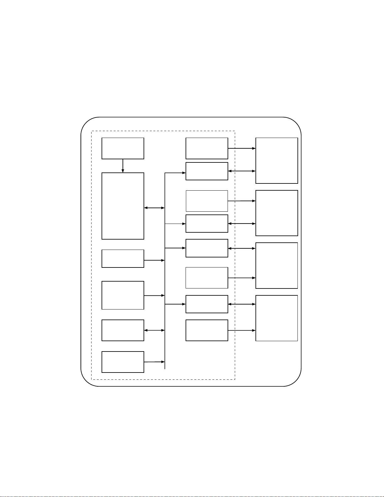
1-4.System block diagram
The system block diagram is shown in Fig 1-1, there are five power supplies in 3301A mainframe
one for 3301A mainframe, and others are for each channel respectively.
The 3301A mainframe is optically isolated with each load module.
3310 MAINFRAME
POWER
SUPPLY
#5
SYSTEM
CONTROLLER
(CPU,RAM,
NON-VOLATILE
RAM,I/O etc.)
POWER
SUPPLY
#1
ISOLATED I/O
INTERFACE #1
POWER
SUPPLY
#2
ISOLATED I/O
INTERFACE #2
ISOLATED I/O
INTERFACE #3
IEEE-488
INTERFACE
MAINFRAME
OPERATION
KEY
STORE/RECALL
MASTER/SLAVE
DIO INTERFACE
POWER
SUPPLY
#4
POWER
SUPPLY
#3
ISOLATED I/O
INTERFACE #4 3320
SERIES
PLUG-IN
LOAD
MODULE
#4
3320
SERIES
PLUG-IN
LOAD
MODULE
#3
3320
SERIES
PLUG-IN
LOAD
MODULE
#2
3320
SERIES
PLUG-IN
LOAD
MODULE
#1
9931 REMOTE
CONTROL
INTERFACE
Figure 1-1 Block diagram

3301A MAINFRAME OPERATION MANUAL 3
ˍˍˍˍˍˍˍˍˍˍˍˍˍˍˍˍˍˍˍˍˍˍˍˍˍˍˍˍˍˍˍˍˍˍˍˍˍˍˍˍˍˍˍˍˍˍˍˍˍˍˍˍˍˍˍˍˍˍˍ
Chapter 2 Installation
2-1.Inspection
The 3301A mainframe was carefully inspected before shipment. If instrument damage has occurred
during transport, please inform Prodigit's sales and service office or representative.
Your 3301A mainframe was shipped with a power cord for the type of outlet used at your
location. If the appropriated cord was not included, please contact your nearest Prodigit
sales office to obtain the correct cord. Refer to " check line voltage " to check the line
voltage selection and fuse type.
2-2.Check line voltage
The 3301A mainframe and 3320 series Electronic load can operation with 100, 115, 200, 230Vac
input as indicated on the label on the rear panel.
Make sure that the factory check mark correspond to your nominal line voltage. Skip this
procedure if the label is corrected marked.
1.With the 3301A mainframe power OFF, disconnect the power cord, and remove two bottom cover
screws.
2.Turn the 3301A mainframe up side down, remove the bottom cover.
3.Refer the drawing on the PC board in Fig 2-1, set the switches to the proper voltage as
describe in the following:
a.115Vac:Set SW1 to left side (SW1Å).
b.230Vac:Set SW1 to right side (SW1Æ).
POWER SUPPLY PCB
SW1
115V 230V
Figure 2-1 Set of the power switch
4.Replace the cover and mark the correct voltage on the rear panel of 3301A mainframe.
5.Check the rating of the line fuse and replace it with the correct fuse if necessary.
6.The line fuse is located below the AC line receptacle see Fig 2-2. With the power cord
removed, use a small screwdriver to extract the fuse holder from under the AC socket.
Replace the fuse with the appropriate type as indicated in table 1-1. These fuses are
normal-blow fuses.

4 PRODIGIT
ˍˍˍˍˍˍˍˍˍˍˍˍˍˍˍˍˍˍˍˍˍˍˍˍˍˍˍˍˍˍˍˍˍˍˍˍˍˍˍˍˍˍˍˍˍˍˍˍˍˍˍˍˍˍˍˍˍˍˍ
Figure 2-2 AC line receptacle socket
7.Reinstall fuse holder and connect the power cord.
2-3.Grounding requirements
Model 3301A mainframe and 3320 series Plug-in load is equipped with three conductor calbe
which plugges in an appropriate receptacle to ground the instrument's cover.
2-4.Adjust the feet
The 3301A Electronic load mainframe is equipped with feet and tilt stands installed and is
ready for used as a bench instrument. The feet provide a good viewing angle for bench-top use.
2-5.Rack mount
The 3301A mainframe is designed to permit mounted in a standard 19 inches rack for system
application.
2-6.Enviremental requirements
The operating temperature should keep etween 0 degree and 40 degree, while the ideal operating
temperature 25 ±5 degree.
2-7.Repairing
If the instrument is damaged, please attach a tag to the instrument to identify the owner and
indicated the require service or repairing. And inform the Prodigit sales and service office
or representative.

3301A MAINFRAME OPERATION MANUAL 5
ˍˍˍˍˍˍˍˍˍˍˍˍˍˍˍˍˍˍˍˍˍˍˍˍˍˍˍˍˍˍˍˍˍˍˍˍˍˍˍˍˍˍˍˍˍˍˍˍˍˍˍˍˍˍˍˍˍˍˍ
2-8.Accessories
The following parts should be include in the shipment.
1.Three conductor power cord 1pc
2.3301A mainframe operation manual 1pc
2-9.GPIB connection
The GPIB connector on the rear panel connects the 3301A mainframe to the controller and to
other GPIB devices. An GPIB system can be connected in any configuration ( star, linear, or
both ) as long as;
1.The maximun number of devices including the controller is no more than 15.
2.The maximum length of all cable in no more than 2 meters times the number of devices
connected together, up to 20 meters maximum.
Please make sure the lock screws are firmly hand - tightened, use a screwdriver only for
the removal of screws.
Fig 2-3 shows the rear panel of 3301A mainframe, the GPIB connector and GPIB address
setting switch is located on the rear panel of 3301A mainframe.
0
1
16842
LINE FUSE RATING
100V
115V
200V
230V
50/60 Hz
2A
1A
LINE INPUT
GPIB ADDRESS
1DIO CONTROL ANALOG PROGRAMMING INPUT
CH2 CH1CH3CH4
3310 SERIES USED ONLY.
PRODIGIT ELECTRONICS CO., LTD
0 10 Vac+dc
R
EXTERNAL REMOTE CONTROLLER
(5 RECALL MEMORY)
MADE IN TAIWAN, TAIPEI, R.O.C.
MASTER/SLAVE
Figure 2-3 rear panel
The GPIB address of the 3301A mainframe is factory set to address 05. The GPIB address can
be set by adjust the GPIB address switch setting the weighting of the address switch is
following from left to right in 1, 2, 4, 8, 16 sequence.
The unused switch should set to OFF position.

6 PRODIGIT
ˍˍˍˍˍˍˍˍˍˍˍˍˍˍˍˍˍˍˍˍˍˍˍˍˍˍˍˍˍˍˍˍˍˍˍˍˍˍˍˍˍˍˍˍˍˍˍˍˍˍˍˍˍˍˍˍˍˍˍ
The switch 1 and 3 are in ON position for address 05 when the 3301A mainframe is shipped
from Prodigit. Fig 2-4 shows the detail outlook of the address switch.
12345678ON
124816
ADDRESS
No.
Figure 2-4 Address switch
2-10.Remote control Port
The D-sub 9 pin connector on the rear panel connects the 3301A mainframe to the PRODIGIT mode
9931 remote controller and to replace the RECALL option key 1 to 5 on the front panel of 3301A
mainframe.
1
2
3
4
5
STORE
1
2
3
4
5
6
7
8
9
NC
NC
NC
NC
D-sub 9 Pin
PRODIGIT
INSTRUMENT PRO.
9931 REMOTE INTERFACE
9 Pin to 9 Pin 1.5M Cable
1
2
3
4
5
Figure 2-5 Diagram of Remote Control Port

3301A MAINFRAME OPERATION MANUAL 7
ˍˍˍˍˍˍˍˍˍˍˍˍˍˍˍˍˍˍˍˍˍˍˍˍˍˍˍˍˍˍˍˍˍˍˍˍˍˍˍˍˍˍˍˍˍˍˍˍˍˍˍˍˍˍˍˍˍˍˍ
2-11.Master/Slave operating mode
Fig 2-6 shows the connection of two 3301A mainframe is Master/Slave operating mode. The
connection method is shown below:
1.The Master unit of 3301A mainframe's rear panel connects the GPIB cable to the controller
(computer)
2.Use 25 pin "D" type cable to connect two 3301A mainframe (Master and Slave unit)
3.The channel number of Master / Slave operating is shown in Fig 2-7, i.e.; in the Master
unit from left to right:ch1, ch2, ch3 and ch4, and in Slave unit from left to right: ch5,
ch6, ch7 and ch8 respectively.
4.Please disconnect the 25 pin "D" type cable when Master / Slave operating mode is not used.
CH1 CH2 CH3 CH4 CH1 CH2 CH3 CH4
COMPUTER
GPIB CABLE DC LOAD
MASTER SLAVE
D-SUB 25Pin
CABLE DC LOAD
Figure 2-6 The channel number of Master/Slave operation

8 PRODIGIT
ˍˍˍˍˍˍˍˍˍˍˍˍˍˍˍˍˍˍˍˍˍˍˍˍˍˍˍˍˍˍˍˍˍˍˍˍˍˍˍˍˍˍˍˍˍˍˍˍˍˍˍˍˍˍˍˍˍˍˍ
1
2
3
4
5
6
7
8
9
10
11
12
13
14
15
16
17
18
19
20
21
22
23
24
25
1
2
3
4
5
6
7
8
9
10
11
12
13
14
15
16
17
18
19
20
21
22
23
24
25
CABLE
DATA5
DATA6
DATA7
DATA8
CLK5
CLK6
CLK7
CLK8
CONTROL
MASTER/SLAVE
STATIC LOAD
D-SUB 25P Con.
MASTER/SLAVE
STATIC LOAD
D-SUB 25P Con.
TO
SELECTOR TO
SELECTOR
TO DETECTOR
NC
NC
NC
NC
NC
NC
NC
NC
Figure 2-7 25PIN 〝D〞type cable

3301A MAINFRAME OPERATION MANUAL 9
ˍˍˍˍˍˍˍˍˍˍˍˍˍˍˍˍˍˍˍˍˍˍˍˍˍˍˍˍˍˍˍˍˍˍˍˍˍˍˍˍˍˍˍˍˍˍˍˍˍˍˍˍˍˍˍˍˍˍˍ
Chapter 3 Mainframe operation
The front panel of 3301A mainframe is shown in Fig 3-1.
MAINFRAME
ELECTRONIC LOAD
3301A
POWER
SLAVE
1
0
PROT
REM
OTP
LOAD
LOADELECTRONIC
3320 60V
DC 30A,150W
PRODIGIT
INSTRUMENT PROFESSIONAL
SLOWMID.FAST
OFF
ON
OFF
ON
I
- DC INPUT +
SENSEMONITOR V
I
F.S. 10V
II
RATE
SLEW
RANGE SHORT
LOAD PRES
SLOWMID.FAST
OFF
ON
OFF
ON
I
- DC INPUT +
SENSEMONITOR VI
F.S. 10V
II
RATE
SLEW
RANGE SHORT
LOAD PRES
PRODIGIT
INSTRUMENT PROFESSIONAL
300W60A,
DC 60V
3321
ELECTRONICLOAD
LOAD
OTP
REM
PROT V
A
PRODIGIT
INSTRUMENT PROFESSIONAL
300W10A,
DC 250V
3322
ELECTRONICLOAD
LOAD
OTP
REM
PROT V
A
PRODIGIT
INSTRUMENT PROFESSIONAL
300W10A,
DC 250V
3322
ELECTRONICLOAD
LOAD
OTP
REM
PROT V
A
SLOWMID.FAST
OFF
ON
OFF
ON
I
- DC INPUT +
SENSEMONITOR V
I
F.S. 10V
II
RATE
SLEW
RANGE SHORT
LOAD PRES
SLOWMID.FAST
OFF
ON
OFF
ON
I
- DC INPUT +
SENSEMONITOR VI
F.S. 10V
II
RATE
SLEW
RANGE SHORT
LOAD PRES
STATE:
STORE 1 234 5
Figure 3-1 3301A front panel
3-1.Feet stands
There are four feet which are located in each corner of the 3301A bottom plate.
The two feet on the front panel side are equipped with stainless tilt stands, you can pull up
the tilt stands to provide a good view angle of the 3320 series Electronic load module in the
manual operation.
3-2.Power switch
Before connecting AC power to the 3301A mainframe, make sure the power source matches the
power requirements of the 3301A Electronic load mainframe (as mark on the rear panel) Power
switch turns 3301A mainframe and 3320 series Electronic load module ON or OFF, when the 3301A
mainframe is first turn ON, the 3301A mainframe and 3320 series Electronic load module's front
panel status is indicated with the following configuration.
3301A: 1.Local manual operation mode.
2.STORE / RECALL:No function;3320 series Electronic load is in power on initial
state.
3320 : 1.Load OFF
2.Preset OFF
3.Range I
4.Short OFF
5.Slew rate:SLOW
6.Load current level:OA

10 PRODIGIT
ˍˍˍˍˍˍˍˍˍˍˍˍˍˍˍˍˍˍˍˍˍˍˍˍˍˍˍˍˍˍˍˍˍˍˍˍˍˍˍˍˍˍˍˍˍˍˍˍˍˍˍˍˍˍˍˍˍˍˍ
3-3.STORE/RECALL operation
The six function keys on the front panel of 3301A mainframe are designed for high testing
throughput purpose. There are five operating states or testing steps can be stored in the non-
volatile memory of 3301A mainframe, each state can save or recall the load status and load
level four 3320 series Electronic load modules simultaneously.
STORE procedure:
1.Set the load status and load level from channel 1 to channel 4 respectively.
2.Press the STORE key on the 3301A mainframe, the STORE LED annuciator is flashing. (about
two times *every second)
3.Press one of the state 1-5 key, the appropriate state key's LED annuciator will be lit
immediately, the load level and status of 4 channel's 3320 load module is stored into the
non-volatile memory this time. Then, the STORE LED annuciator turn to blank, it means the
STORE procedure is completed.
Note:
1.After press the STORE key, the STORE LED annuciator will flash for 10 seconds, if the STATE 1-5
key is not pressed within this 10 seconds, the STORE LED annuciator will be blank, it indicated the
STORE process is not available now, please repeat the STORE procedure for a new STORE
operation.
2.After press the STORE LED key, then press the STORE key again, the STORE LED annuicator will
be blank, it indicate the STORE process in not available.
3.After press the STORE key, it is available and useful to operate the front panel key on the 3320
series Electronic load module.
STORE function:
Please refer Chapter section on the 3320 series Electronic load module operation manual to
more detail operating flow chart for the store and recall operation.
It can store up to 5 states of four channel's load module setting simultaneously, if you store
2 different states in the same state key, then the later state will overcome the previous
state, it acts as update the new data.
RECALL operation:
Press one of the state 1 through 5 key, the appropriate LED annuciator will be lit, the store
state on the 3301A mainframe is sending to the 4 channel's 3320 series Electronic load module
simultaneously. Before press the state key, you press any key on any channel, then the state
LED annuicator is blank immediately, it indicates the STORE state has been changed by
readjustment on the load module's front panel.

3301A MAINFRAME OPERATION MANUAL 11
ˍˍˍˍˍˍˍˍˍˍˍˍˍˍˍˍˍˍˍˍˍˍˍˍˍˍˍˍˍˍˍˍˍˍˍˍˍˍˍˍˍˍˍˍˍˍˍˍˍˍˍˍˍˍˍˍˍˍˍ
Chapter 4 GPIB programming operation
4-1.The summary of GPIB command
Table 4-1 GPIB command listing
COMMAND FUNCTION
CHAN Channel selecting
CLE Clear to initial state
CURR Current level programming
LOAD Set load input ON OFF condition
MASTER Select Master or Slave operation mode
PRES Preset load current level to be display on DCM and
Imonitor
RANGE Select the full scale current range
RECALL Recall the store state
SHOR Set load input to short circuit
SLEW Load current slew rate control
SPEC Set the specification for each load module
STORE Store the present load state and load level
TRIG Excecute the commands which is waiting for trigger
Table 4-1 GPIB Command listing
4-2.The description of abstraction
1.SP:Space, the ASCII code is 20 Hexadecimal.
2.;:Semicolon, Program line terminator, the ASCII code is OA Hexadecimal.
3.NL:New line, Program line terminator, the ASCII code is OA Hexadecimal.
4.N:Integer number from 1 tp 8.
5.NR2:Digits with decimal point. It can be accepted in the range and formate of ##.#####.
For example:30,12345, 5.0
The description of GPIB programming command syntax.
1.{ }:The contents of the { } symbol must be used as a part or data of the GPIB command, it
can not be omitted.
2. [ ]:The contents of the [ ] symbol indicts the command can be used or not. It depends on
th testing application.
3.|:This symbol means option. For example "A|B" means it can only use A or B as the
command, it can choose only one as the setting command.

12 PRODIGIT
ˍˍˍˍˍˍˍˍˍˍˍˍˍˍˍˍˍˍˍˍˍˍˍˍˍˍˍˍˍˍˍˍˍˍˍˍˍˍˍˍˍˍˍˍˍˍˍˍˍˍˍˍˍˍˍˍˍˍˍ
4."TRIG":The command will not be excuted immediately until the GPIB TRIG command is sent by
computer, the load level or load status are stored in the data buffer before the GPIB TRIG
command program line is excuted.
5.Terminator: You have to send the program line terminator charactor after send the GPIB
command, the available command terminator characters which can be accepted in 3301A
mainframe is listed in table 4-2.
LF
LF WITH EOI
CR,LF
CR,LF WITH EOI
Table 4-2 GPIB command terminator
A terminator informs GPIB that it has reached the end of statement. Normally, this is sent
automatically by your GPIB programming statements. In this manual, the terminator is
assumed at the end of each example line of code. If it needs to be indicated, it is shown
by symbol (nl); which stand for " new line "and represents ASCII code byte the OA
Hexadecimal or 10 decimal.
6.Semicolon ";":The semicolon " ; " is a back-up command, it instructs the parser to return
to the previous colon, the semicolon allows you to combine command statement on one line to
create command message.
7.GTL : The REM LED annuciator of each load module will turn ON when the 3320 series
Electronic load module is in remote operation mode. The GTL (GO TO LOCAL) command returns
the Electronic load module to manual or front panel operation, the LED annuciator will turn
OFF as well in the manual operation mode. The ACSII code for GTL command is 01 Hexadecimal.

3301A MAINFRAME OPERATION MANUAL 13
ˍˍˍˍˍˍˍˍˍˍˍˍˍˍˍˍˍˍˍˍˍˍˍˍˍˍˍˍˍˍˍˍˍˍˍˍˍˍˍˍˍˍˍˍˍˍˍˍˍˍˍˍˍˍˍˍˍˍˍ
4-3.GPIB command description
CHAN
Purpose :
" CHAN " selects the multiple Electronic load channel to which all subsequent channel
specific command will be directed.
Command syntax :
CHAN {SP}{N}{;NL}
Description :
" CHAN " command selects the specified Electronic load module from 1 through 8 as the
Electronic load module number. It can be installed up to 4 channels of the Electronic load
module in one mainframe or up to 8 channels of the Electronic load module if the Master /
Slave 25 pin "D" type cable is connected between two 3301A mainframe.
The load channel number is arranged as 1,2,3,4 from left hand side to the right hand side
respectively, or 1,2,3,4 for from the left hand side to the right hand side of the Master
3301A mainframe, and 5,6,7,8 for from the left hand side to the right hand side of the
Slave 3301A mainframe.
Example :
Select Channel 1
CHAN 1
Select Channel 5
CHAN 5
CLE
Purpose :
Clear to the initial state
Command syntax :
CLE{;NL}
Description :
This command clear the Electronic load's load status and load level to the initial power
ON state.
The power ON state of the 3320 Electronic load module is Load OFF Preset OFF Range I Short
OFF Slew rate:Slow Load current level OA
The CLE command does not clear or effect the data which is stored by STORE command, for the
data is stored in the non-volatile memory on the 3301A mainframe.
Example :
a.CLE

14 PRODIGIT
ˍˍˍˍˍˍˍˍˍˍˍˍˍˍˍˍˍˍˍˍˍˍˍˍˍˍˍˍˍˍˍˍˍˍˍˍˍˍˍˍˍˍˍˍˍˍˍˍˍˍˍˍˍˍˍˍˍˍˍ
CURR
Purpose :
Constant load current setting.
Command syntax :
CURR:[:TRIG]{SP}{NR2}{;NL}
Description :
This command is used to set the load current level of 3320 series Electronic load module.
Note:
1.The load current data must include decimal point, otherwise this command is unable to excute.
2.Unit for load current is ampere.
3.Please make sure the SPEC command and range I / II command before excute the load current
setting command.
4.If the programming load current level over the maximum specification of 3320 series load module,
the full scale current will be sent to the load module.
5.The most effective load current level can be set is the fifth digit after the decimal point.
Example :
1.CURR:TRIG 10.20
2.CURR:3.0
3.CURR:5.123
LOAD
Purpose :
Turn the Electronic load module input ON or OFF.
Command syntax :
LOAD[:TRIG]{SP}{ON|OFF}{;NL}
Description :
This command sets the Electronic load to sink current from DC power source.
LOAD ON:Electronic load is ready to sink current from DC power source.
LOAD OFF:Electronic load can not sink current from DC power source.
Example :
a.LOAD ON
b.LOAD:TRIG ON
c.LOAD:TRIG OFF

3301A MAINFRAME OPERATION MANUAL 15
ˍˍˍˍˍˍˍˍˍˍˍˍˍˍˍˍˍˍˍˍˍˍˍˍˍˍˍˍˍˍˍˍˍˍˍˍˍˍˍˍˍˍˍˍˍˍˍˍˍˍˍˍˍˍˍˍˍˍˍ
MASTER
Purpose :
Select 4 or 8 channel load modules to be controlled when Master/Slave "D" type cable is
connected between two 3301A mainframe and only one GPIB interface is used.
Command syntax :
MASTER{SP}{ON|OFF}{;NL}
Note:
Default Master OFF
Description :
MASTER ON control up to 8 channels of the Electronic load module if the Master/Slave "D"
type cable is connected on real panel of the two 3301A mainframe. At this time, the second
unit of 3301A mainframe ( it is connected by 25 pin "D" type connector only, the GPIB cable
is not connected in this unit ). SLAVE LED annuciator on the lower and right hand corner of
the 3301A mainframe is lit, and the REM LED annuciator of each load module is lit also to
indication remote programming operation.
MASTER OFF controls up to 4 channels of the Electronic load module in 3301A mainframe.
Example :
Master ON; Control channel 5 - channel 8 of another slave 3301A mainframe.
PRES
Purpose :
Set the 4 1/2 digit current Meter to display the programming load current level.
Command syntax :
PRES[:TRIG]{SP}{ON|OFF}{;NL}
Description :
The PRESET ON command set the 4 1/2 DCM and Imonitor BNC output to display or output the
programming load current level.
PRES OFF Command set the 4 1/2 DCM to display the actual load current which current is down
through the load input, and the Imonitor BNC output signal is proportional to the actual
load current.
Example :
a.PRES ON
b.PRES OFF
c.PRES:TRIG ON

16 PRODIGIT
ˍˍˍˍˍˍˍˍˍˍˍˍˍˍˍˍˍˍˍˍˍˍˍˍˍˍˍˍˍˍˍˍˍˍˍˍˍˍˍˍˍˍˍˍˍˍˍˍˍˍˍˍˍˍˍˍˍˍˍ
RANG
Purpose :
Select the operating full scale current range.
Command syntax :
RANG{SP}{1|2}{;NL}
Description :
This command selects the full scale current range of the Electronic load. There are two
full scale current range for each 3320 series Electronic load module. Table 4-3 shows the
range I/II full scale current for each 3320 series load module.
When RANG command is excuted, the values of the current level are adjusted as follow:
1.IF the existing current setting is within the new range. Then the current level does not
change.
2.IF the existing current is setting in not within the new range. Then the current level
is set to the maximum of new range.
The maximum load current level is shows in table 4-3.Table 4-3 maximum full scale
current level for each module.When the programming load level setting is greater than
the maximum current level of each range of each module, then the load current will
adjust to the maximum current level which is listed in table 4-3.
MODEL 3320 3321 3322 3323 3324 3325
RANGE I 3.072 6.142 1.024 1.024 0.511 1.535
RANGE II 30.72 61.42 10.24 10.24 5.11 15.36
Table 4-3 Maximun load current level
RECALL
Purpose :
Recall the state of load level and load status which is stored by GPIB STORE command.
Command syntax :
RECALL{SP}{1|2|3}{;NL}
Description :
This command is used to recall the non-volatile memory state which is stored into the
memory by GPIB store command, up to 5 states can be recalled.
Example :
a.RECALL 1
b.RECALL 4
SHOR

3301A MAINFRAME OPERATION MANUAL 17
ˍˍˍˍˍˍˍˍˍˍˍˍˍˍˍˍˍˍˍˍˍˍˍˍˍˍˍˍˍˍˍˍˍˍˍˍˍˍˍˍˍˍˍˍˍˍˍˍˍˍˍˍˍˍˍˍˍˍˍ
Purpose :
Short the DC input of Electronic load.
Command syntax :
SHOR[:TRIG]{SP}{ON|OFF}{;NL}
Description :
This command applies the short across the input of the Electronic load. The maximum short
resistance is 0.03, 0.02 and 0.04 ohms for 3320, 3321 and 3322 Electronic load module
respectively.Excuting SHOR does not effect any programmed settings and the Electronic load
will return to them when the short is removed.
Example :
a.SHOR ON
b.SHOR OFF
c.SHOR:TRIG ON
SLEW
Purpose :
SET the slew rate of load current change.
Command syntax :
SLEW{SP}{1|2}{;NL}
Description :
This command selects the load current slew rate SLOW, MIDDLE and FAST with its code 1, 2
and 3 respectively. The code for each slew rate is shown in Table 4-4.For detail load
current slew rate for SLOW, MIDDLE, FAST, and each model of 3320 series Electronic load
module, please refer the 3320 series Electronic load operation manual. Table 4-4 slew rate
code for SLOW, MID, AND FAST.
SLEW RATE CODE
SLOW 1
MIDDLE 2
FAST 3
Table 4-4 Slew rate code for SLOW, MID, and FAST
Example :
a.SLEW 1
b.SLEW 2
c.SLEW 3
Table of contents
Other Prodigit Motherboard manuals


