Prodigit 3302C Series User manual

3302C
Mainframe
Operation Manual
P/N:90033024 REV:G

Material Contents Declaration
(材料含量宣称)
Hazardous Substance (有毒有害物质或元素)
(Part Name)
零件名称 铅
(Pb)
汞
(Hg)
镉
(Cd)
六价铬
(Cr6+)
多溴
联苯
(PBB)
多溴
二苯醚
(PBDE)
PCBA
(印刷电路装配件)X O X OOO
Electrical part not on PCBA’s
未在PCBA上的电子零件 X OX OOO
Metal parts
金属零件 OOOX OO
Plastic parts
塑料零件 OOOOX X
Wiring
电线 X OOOOO
Package
封装 X OOOOO
对销售之日的所售产品,本表显示, PRODIGIT 供应链的电子信息产品可能包含这些物质。注意:在所售产品中可能
会也可能不会含有所有所列的部件。This table shows where these substances may be found in the supply chain
of Prodigit electronic information products, as of the date of sale of the enclosed product. Note that some of the
component types listed above may or may not be a part of the enclosed product. ○:表示该有毒有害物质在该部
件所有均质材料中的含量均在SJ/T 11363-2006 标准规定的限量要求以下。○:Indicates that the concentration of
the hazardous substance in all homogeneous materials in the parts is below the relevant threshold of the SJ/T
113632006 standard. ×:表示该有毒有害物质至少在该部件的某一均质材料中的含量超出SJ/T 11363-2006 标准
规定的限量要求。×:Indicates that the concentration of the hazardous substance of at least one of all
homogeneous materials in the parts is above the relevant threshold of the SJ/T 11363-2006 standard.
Note(注释):
1.Prodigit has not fully transitioned to lead-free solder assembly at this moment;However, most of the
components used are RoHS compliant.
(此刻,Prodigit 并非完全过渡到无铅焊料组装;但是大部份的元器件一至于RoHS的规定。)
2. The product is labeled with an environment-friendly usage period in years.
The marked period is assumed under the operating environment specified in the product specifications.
(产品标注了环境友好的使用期限制(年)。所标注的环境使用期限假定是在此产品定义的使用环境之下。)
Example of a marking for a 10 year period:
(例如此标制环境使用期限为10年)

3302C Series Mainframe Operation Manual Table of Contents
Chapter 1 Introduction......................................................................................... 1-1
1.1 Features ................................................................................................... 1-2
1.2 Option....................................................................................................... 1-2
1.3 Specifications ........................................................................................... 1-2
1.4 System block diagram .............................................................................. 1-3
Chapter 2 Installation........................................................................................... 2-1
2.1 Inspection .............................................................................................................2-1
2.2 Check line voltage...............................................................................................2-1
2.3 Grounding requirements ....................................................................................2-2
2.4 Environmental requirements..............................................................................2-2
2.5 Observe the International Electrical Symbol listed below.............................2-2
2.6 Cleaning and Storage.........................................................................................2-3
2.7 Repairing ..............................................................................................................2-3
2.8 Accessories..........................................................................................................2-3
2.9 GPIB connection..................................................................................................2-3
2.10RS-232C Connection..........................................................................................2-4
2.11Remote control Port............................................................................................2-4
2.12Analog programming BNC input .......................................................................2-4
Chapter 3 Mainframe operation........................................................................... 3-1
3.1 Power switch........................................................................................................3-1
3.2 Power on status...................................................................................................3-2
3.3 STORE / RECALL operation .............................................................................3-3
3.4 AUTO SEQUENCE testing function description ............................................3-4
Chapter 4 GPIB/RS-232 programming operation............................................... 4-1
4.1 Introduction...........................................................................................................4-1
4.2 The summary of RS-232 interface and command .........................................4-1
4.3 GPIB/RS-232C COMMAND LIST.....................................................................4-2
4.4 The description of abbreviation.........................................................................4-7
4.5 GPIB/RS-232 command description ................................................................4-8
Appendix A GPIB programming Example..........................................................A-1
Appendix B RS-232 programming Example.......................................................B-1
Appendix C 3250A Series GPIB/RS-232 Operating flow chart..........................C-1
Appendix D 3310A Series GPIB/RS-232 Operating flow chart..........................D-1
Appendix E 3330A Series GPIB/RS-232 Operating flow chart..........................E-1
Appendix F 3320 Series GPIB/RS-232 Operating flow chart.............................F-1
Appendix G 3310C Series GPIB/RS-232 Operating flow chart......................... G-1

Figures
Fig 1-1 BLOCK DIAGRAM .............................................................................. 1-3
Fig 2-1 SET OF SWITCH ................................................................................ 2-1
Fig 2-2 AC LINE RECEPTACLE...................................................................... 2-2
Fig 2-3 3302C REAR PANEL .......................................................................... 2-3
Fig 2-4 Diagram of Remote Control Port ......................................................... 2-4
Fig 3-1 3302C FRONT PANEL........................................................................ 3-1
Fig 3-2 3302C FRONT PANEL KEY SWITCH................................................. 3-2
Fig 3-3 AUTO SEQUENCY FUNCTION OPERATION FLOW-CHART ........... 3-4
Fig 3-4 STORE (EDIT) MODE OPERATIONO FLOW-CHART ....................... 3-5
Fig 3-5 TEST MODE OPERATION FLOW-CHART......................................... 3-6
Fig 4-1 Rs-232 INTERFACE DIAGRAM.......................................................... 4-1
Tables
Table 1-1 3250A/3310A/3310C/3330A and 3320 SERIES SIMPLE
SPECIFICATION LIST .................................................................................... 1-1
Table 1-2 SPECIFICATIONS........................................................................... 1-2
Table 4-1 GPIB/RS-232 SETTING COMMAND SUMMARY ........................... 4-2
Table 4-2 GPIB/RS-232 QUERY COMMAND SUMMARY.............................. 4-3
Table 4-3 different description ......................................................................... 4-6
Table 4-4 GPIB command terminator .............................................................. 4-7
Table 4-5 waveform information .................................................................... 4-15
Table 4-6 RANGE I/II FULL SCALE CURRENT FOR 3310/3320 SERIES LOAD
...................................................................................................................... 4-21
Table 4-7 PROT status byte register ............................................................. 4-28

3302C Series Mainframe Operation Manual 1-1
Chapter 1 Introduction
The 3302C Electronic load mainframe is designed to install the single channel
3250A/3310A/3310C/3330A and 3320 series plug-in load module,
3250A/3310A/3310C/3330A and 3320 series plug-in module simple specification as table
1-1. Please contact your local PRODIGIT distributor or PRODIGIT sales dept. for detail
specification.
Model Max. current Max. voltage Max. power
3250A 20 Arms 60 Vrms 300 W
3251A 8 Arms 150 Vrms 300 W
3252A 4 Arms 300 Vrms 300 W
3253 1Arms 300 Vrms 300 W
3310C 30A 60V 150W
3311C 60A 60V 300W
3312C 10A 250V 300W
3314C 5A 500V 200W
3315C 15A 60V 75W
3310A 30 A 60 V 150 W
3311A 60 A 60 V 300 W
3312A 10 A 250 V 300 W
3314A 5 A 500 V 200 W
3315A 15 A 60 V 75 W
3320 30A 60V 150W
3321 60A 60V 300W
3322 10A 250V 300W
3324 5A 500V 200W
3325 15A 60V 75W
3330A 50A/5A +60V/+60V 250W/50W
3331A 50A/5A +60V/-60V 250W/50W
3332A 5A/5A +60V/+60V 75W/75W
3333A 5A/5A +60V/-60V 75W/75W
3334A 5A/5A -60V/-60V 75W/75W
3335A 100A/5A +60V/+60V 500W/50W
Table 1-1 3250A/3310A/3310C/3330A and 3320 SERIES SIMPLE SPECIFICATION LIST

1-2 PRODIGIT
1.1 Features
3302C mainframe provides high performance easy operation and cost effective
solution for power source testing, the features of the 3302C electronic load
mainframe is described in the following :
1.1.1 Plug-in design, it is easy to replace different specifications load module.
1.1.2 Flexible configuration, 3302C mainframe can be installed one of 3250A,
3310A, 3310C, 3320 or 3330A series load module.
1.1.3 RS-232 connector provides RS-232 interface for remote control, it can be
used to connect NOTEBOOK PC with RS-232 interface.
1.1.4 The analog programming BNC input on the rear panel can control the load
module's load current with an arbitrary waveforms.
1.1.5 Built-in GPIB interface, GPIB address can control electronic load modules
with set load status and read back meter capabilities.
1.2 Option
1.2.1 GPIB interface
1.2.2 GPIB cable 1 M
1.2.3 GPIB cable 2 M
1.2.4 9931C Remote Controller 1 Set
1.2.5 D-SUB 9 Pin to D-SUB 9 Pin cable 1 M
1.2.6 IEEE-488 Interface Card 1 Pc
1.3 Specifications
The detail specification of 3302C mainframe is shown in Table 1-2.
LINE
100V/115V±10﹪200V/230V±10﹪
AC INPUT FREQUENCY 50/60 HZ
FUSE 1A/250V (5*20mm) 0.5A/250V
(5*20mm)
MAX. POWER
CONSUMPTION
40 W
DIMENSIONS (W*H*D) 150 mm*177 mm*445 mm
WEIGHT NET : 5.5 Kg
Table 1-2 SPECIFICATIONS

3302C Series Mainframe Operation Manual 1-3
1.4 System block diagram
The system block diagram is shown in Fig 1-1, there are two power supplies in
3302C mainframe one for 3302C mainframe, and others are for load module.
The 3302C mainframe is optically isolated with load module.
POWER
SUPPLY
POW
ER
SUPPLY
ISO. I/O
3250/3310A
3310C/3330A
and 3320
SERIES
MODULAR
PLUG-IN
LOAD
SYSTEM
CONTROLLER
(CPU, RAM,
ROM, I/O
etc.)
REAR PANEL
IEEE-488
INTERFACE
REAR PANEL
RS 232
INTERFACE
3300C MAINFRAME
9931C
Remote Output Analog Programming
Remote Input
Fig 1-1 BLOCK DIAGRAM

3302C Series Mainframe Operation Manual 2-1
Chapter 2 Installation
2.1 Inspection
The 3302C mainframe was carefully inspected before shipment. If instrument
damage has occurred during transport, please inform Prodigit's sales and service
office or representative.
Your 3302C mainframe was shipped with a power cord for the type of outlet used at
your location. If the appropriated cord was not included, please contact your
nearest Prodigit sales office to obtain the correct cord. Refer to " check line voltage
" to check the line voltage selection and fuse type.
2.2 Check line voltage
The 3302C mainframe and 3250A/3310A/3310C/3330A/3320 series electronic load
can operation with 100, 115, 200, 230Vac input as indicated on the label on the
rear panel.
Make sure that the factory check marks correspond to your nominal line voltage.
Skip this procedure if the label is corrected marked.
2.2.1 With the 3302C mainframe power OFF, disconnect the power cord.
2.2.2 Refer the drawing on the rear panel in Fig 2-1, set the switches to the proper
voltage as describe in the following:
a. Set Switch to 100V/115V for 100Vac or 115Vac line voltage
b. Set Switch to 200V/230V for 200Vac or 230Vac
Note: 100Vac and 200Vac is used for Japan only
Fig 2-1 SET OF SWITCH
2-2 PRODIGIT
2.2.3 Check the rating of the line fuse and replace it with the correct fuse if
necessary.
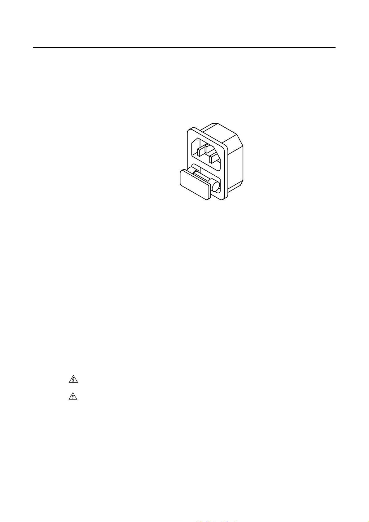
2.2.4 The AC line fuse is located below the AC line receptacle see Fig 2-2. With
the power cord removed, use a small screwdriver to extract the fuse holder
from under the AC socket. Replace the fuse with the appropriate type as
indicated in Table 1-2. These fuses are normal-blow fuses.
2.2.5 Reinstall fuse holder and connect the power cord.
Fig 2-2 AC LINE RECEPTACLE
2.3 Grounding requirements
Model 3302C mainframe and 3250A/3310A/3310C/3330A/3320 series Plug-in load
is equipped with three conductor cable which plugs in an appropriate receptacle to
ground the instrument's cover.
2.4 Environmental requirements
2.4.1 Indoor use.
2.4.2 Installation Category Ⅱ.
2.4.3 Pollution Degree 2.
2.4.4 Altitude up to 2000 Meter.
2.4.5 Relative Humidity 80% Max.
2.4.6 Ambient Temperature 0 ~ 40
2.4.7 While the ideal operating temperature is 25 ±5 degree centigrade.
2.5 Observe the International Electrical Symbol listed below.
Warning!Risk of electric shock.
Caution!Refer to this manual before using the meter.
3302C Series Mainframe Operation Manual 2-3
2.6 Cleaning and Storage
Periodically wipe the case with a damp cloth and detergent; do not use abrasives or
solvents.
2.7 Repairing
If the instrument is damaged, please attach a tag to the instrument to identify the
owner and indicated the require service or repairing. And inform the Prodigit sales
and service office or representative.
2.8 Accessories
The following parts should be include in the shipment.
2.8.1 Three conductor power cord 1pc
2.8.2 GW3302C mainframe operation manual 1pc
2.9 GPIB connection
The GPIB connector on the rear panel connects the 3302C mainframe to the
controller and to other GPIB devices. An GPIB system can be connected in any
configuration (star, linear, or both ) as long as
2.9.1 The maximum number of devices including the controller is no more than 15.
2.9.2 The maximum length of all cable in no more than 2 meters times the number
of devices connected together, up to 20 meters maximum.
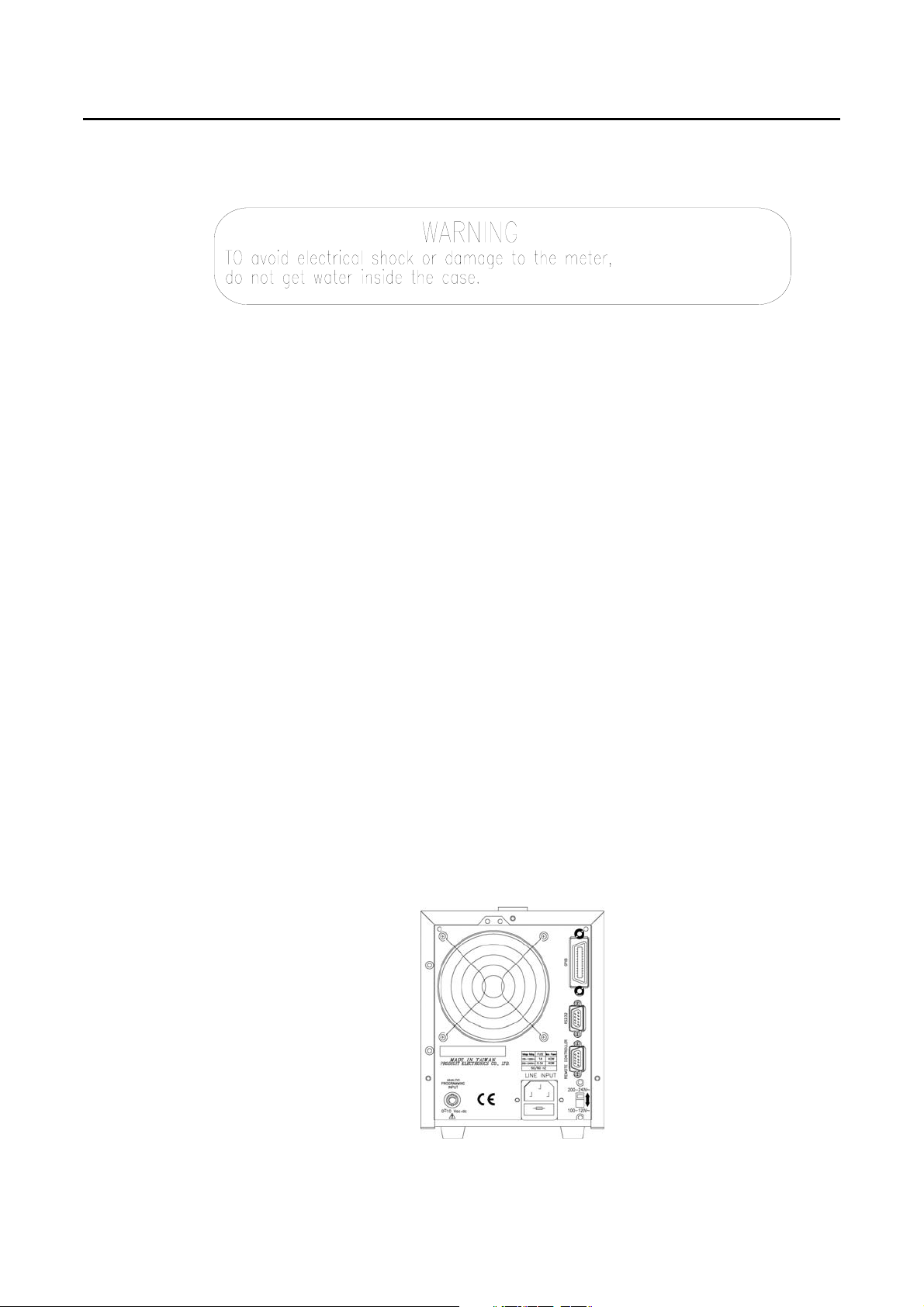
Please make sure the lock screws are firmly hand - tightened, use a screw-
driver only for the removal of screws. Fig 2-3 shows the rear panel of 3302C
mainframe, the GPIB connector is located on the rear panel of 3302C
mainframe. The GPIB address of the 3302C mainframe is set on front panel.
Fig 2-3 3302C REAR PANEL

2-4 PRODIGIT
2.10 RS-232C Connection
The RS-232C connector (Female) on the rear panel connects 3302C mainframe to
RS-232C port of computer in one by one configuration.
2.11 Remote control Port
There are two D-sub 9 pin connector on the rear panel, the Remote Input port
connects the 3302C mainframe to model 9931C remote controller and to replace
the RECALL option key 1 to 5 on the front panel of 3302C mainframe, The LED will
be lit if NG is occurred in any one of load module within 3302C mainframe.
The Remote output port can connect to another 3302C, 3300A or 3302 mainframe
for cascade operation, this feature enable user to control up to 12 or more load
module in a one memory recall operation, it is especially suitable for multiple output
power supply testing applications.
INSTRUMENT PROFESSIONAL
PRODIGIT
9931C REMOTE INTERFACE
9 Pin to 9 Pin Cable
1
2
3
4
5
STORE
1
2
3
4
5
6
7
8
9
NC
NC
D-sub 9 Pin
Fig 2-4 Diagram of Remote Control Port
2.12 Analog programming BNC input
The BNC connector on the rear panel connects the 3302C mainframe to the
3310A/3310C series analog programming input or to the external sync input of
3250A series load module.

3302C Series Mainframe Operation Manual 3-1
Chapter 3 Mainframe operation
The front panel of 3302C mainframe is shown in Fig 3-1.
STATE
STORE
POWE
BANK
START
EXIT
AUTO
SEQ.
ADDR.
Fig 3-1 3302C FRONT PANEL
3.1 Power switch
Before connecting AC power to the 3302C mainframe, make sure the power source
matches the power requirements of the 3302C Electronic load mainframe (as mark
on the rear panel) Power switch turns 3302C mainframe and
3250A/3310A/3310C/3330A and 3320 series Electronic load module ON or OFF,
when the 3302C mainframe is first turn ON, the 3302C mainframe is indicated with
the following configuration.

3-2 PRODIGIT
3.2 Power on status
3302C:
3.2.1 Local/manual operation mode.
3.2.2 STORE/RECALL:All LED is OFF, BABK LED display shows 01; 3302C
series electronic load is in power on initial state.
3.2.3 3250A/3310A/3310C/3330A and 3320 series electronic load is in power up
initial state, please refer to electronic load module's operation manual.
3.2.4 GPIB address setting:
GPIB address is set by press STATE 4 + STATE 5 simultaneously, press UP
or DOWN key to select 0-31 address number, press STATE 2 to exit GPIB
address setting mode.
Fig 3-2 3302C FRONT PANEL KEY SWITCH
STORE
1
2
3
4
5
STATE
START
EXIT
AUTO
SEQ
Addr

3302C Series Mainframe Operation Manual 3-3
3.3 STORE / RECALL operation
The eight function keys on the front panel of 3302C mainframe are designed for
high testing throughput purpose. There are 5 and 150 operation states or testing
steps can be store in the EEROM memory of 3250A/3310A, and 3310C/3330A
series electronic load module respectively, each state can save or recall the load
status and level for four Electronic load modules simultaneously.
3.3.1 STORE procedure:
3.3.1.1 Set the load status and load level from load module within the
mainframe respectively.
3.3.1.2 Skip this procedure for 3250A/3310A series load module, select
the Memory Bank (01-30) to be store for 3310C and 3330A series
load module.
3.3.1.3 Press the STORE key on the 3302C mainframe, the STORE LED
annunciator is flashing (about two times every second) to indicate
ready to store. Press Store key again or wait for about 20 sec to
exit the store operation.
3.3.1.4 Press one of the state 1-5 key, the appropriate state key's LED
annunciator will be lit immediately, the load level and status of
3310 series load module is stored into the EEROM memory this
time. then the STORE LED annunciator turns to OFF, it means the
STORE procedure is completed.
Note:
After press the STORE key, the STORE LED annunciator will flash for 20
seconds, if the STATE 1-5 key is not pressed within this 20 seconds, the
STORE LED annunciator will be OFF, it indicated the STORE process is not
available now, please repeat the STORE procedure for a new STORE
operation.
After press the STORE key, then press the STORE key, then press the
STORE LED annunciator will be blank, it indicate the STORE process is not
available.
After press the STORE key, it is available and useful to operate the front
panel key on the 3310 series Electronic load module. However, the STATE
LED will be OFF if any key on any load module is operated, this indicates the
front panel state of load module is not the same as STORE state.
3.3.2 STORE function:
Please refer chapter section on the 3250A/3310A/3310C/3330A and 3320
series electronic load module operation manual to more detail operation
flow-chart for store and recall operation.
It can store up to states of 3250A/3310A/3310C/3330A and 3320 series load
module setting simultaneously, if you store 2 different states in the same
state key, the later state will overcome the previous state, it acts as update
the new data.

3-4 PRODIGIT
3.3.3 RECALL operation:
3.3.3.1 For 3250A and 3310A series, press one of the Memory State 1
through 5 key, the appropriate LED annunciator will be lit, the
store state on the 3302C mainframe is sending to the electronic
load module simultaneously. Before press the states key, you
press any key on the load module then the state LED annunciator
is blank immediately, it indicates the STORE state has been
changed on load module's front panel.
3.3.3.2 For 3310C and 3330A series, using UP and Down key to select
the Memory Bank, then follow the procedure (a.) for the Memory
Recall operation.
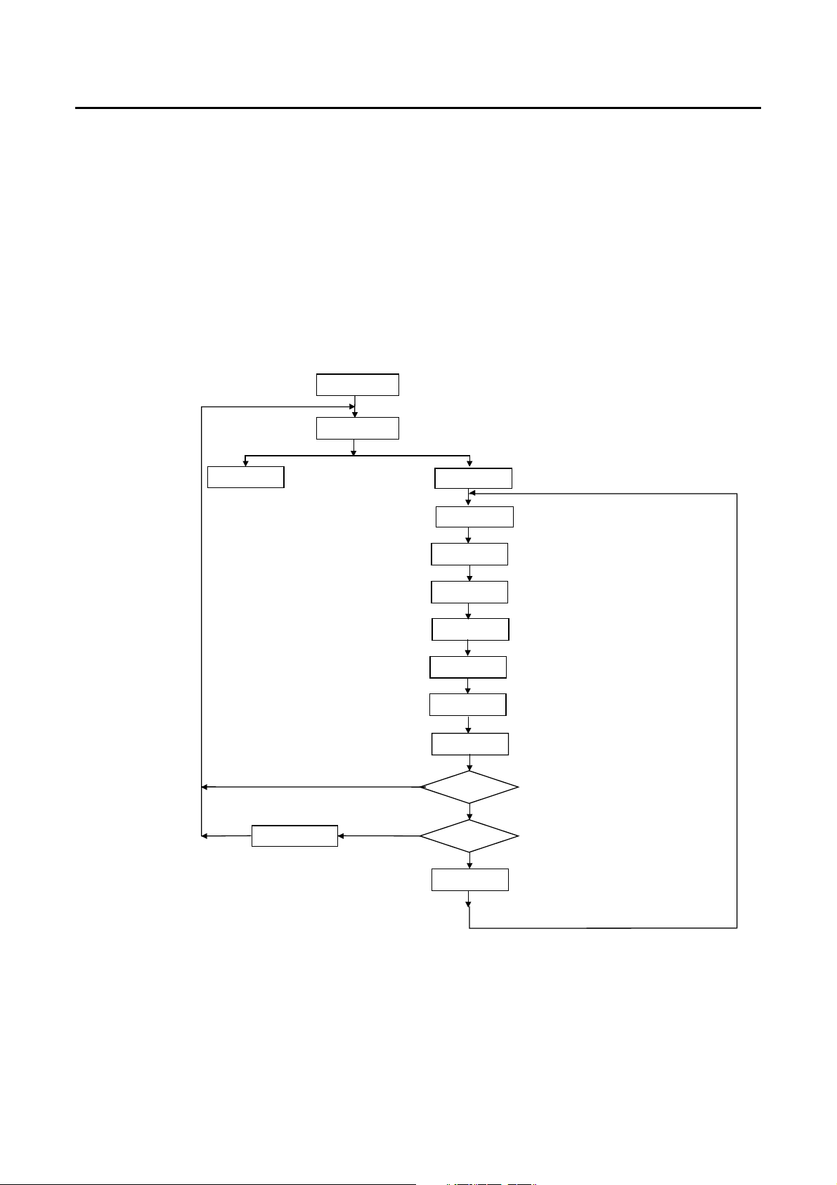
3.4 AUTO SEQUENCE testing function description
There are two modes in AUTO SEQUENCE function, EDIT MODE and TEST
MODE, The AUTO SEQ mode can be entered by press S3 + S4 key
simultaneously, then press STORE key again to enter the EDIT MODE, or press
START key to enter the TEST MODE, Please refer to the flow chart operation
below:
Normal Mode
AUTO SEQ.
Press S3+S4 key
Display bank no.
Press Exit key
bn
Show r1-r9 Display 3300C Firmware version r1-r9
Display bank
STATE MODESTORE MODE
Press STATE keyPress STORE key
Show n1~n9
Fig 3-3 AUTO SEQUENCY FUNCTION OPERATION FLOW-CHART
3.4.1 EDIT MODE
The TEST Mode of Auto-Sequence function is entered by press S3 + S4 key
simultaneously, The EDIT mode of Auto Sequence function is entered by
press S3 + S4 key simultaneously, the S3 and S4 LED are ON to indicate
Auto-sequence mode, then the Edit mode of Auto-sequence function is
proceed by press STORE key.
3302C Series Mainframe Operation Manual 3-5
The EDIT MODE flow chart is described below:
3.4.1.1 There are nine Auto Sequence (n1-n9) can be edit within 3302C
3.4.1.2 Each Auto Sequence has up to 16 Test step, where each step is
any one memory of 150 sets Store memory which is 30 memory
Bank with 5 memory state.
3.4.1.3 Each test step has t1 (test time) and t2 (delay time), the unit is
100mS, the range is 0.1S - 9.9S in 100mS resolution. 3302C
mainframe will check each module GO/NG at the end of t1 (test
time), the next step will be started after duration t2 (delay time).
3.4.1.4 The test step sequence can be up to 16 step, and can be
terminated by press EXIT key if less than 16 step is required.
S3+S4
Show n1-n9
Store Mode
1.Press S3+S4 key
2.Show AUTO SEQ. No.1-No.9,
Press Up/Down key to set n1-n9
Press Store
3.Press Store key to Store Mode
Set Bank Press Up/Down key to set Bank No.
Set State Set State No.1~5
Show t1
Set T1 Press Up/Down key to set T1,
t1 = 01-99, Unit = 100mS
Exit
Press Exit key
Show SP= 0
Set T2
Step = F?
Yes
Yes End?
Sp=Sp+1
Initial=n1~n9
Sp = 0 ~ F(16 step)
Show t2
Press Store key to next item
When press Store key, LED show t1
Press Store key to next item
When press Store key, LED show t2
Press Up/Down key to set T2,
t1 = 00-99, Unit = 100mS
Press Store key to next item
Is last step (16 step)?
Press Exit key
Fig 3-4 STORE (EDIT) MODE OPERATIONO FLOW-CHART

3-6 PRODIGIT
3.4.2 TEST MODE
The TEST Mode of Auto-Sequence function is entered by press S3 + S4 key
simultaneously, the S3 and S4 LED are ON to indicate Auto-sequence mode,
then the Test mode of Auto-sequence function is proceed by press START
key.
The TEST MODE flow chart is described below:
3.4.2.1 After press START key, the 3302C controls all the module within
the mainframe to recall correspond memory which had been
stored in Auto-sequence (n1~n9) memory.
3.4.2.2 The sequence start from (Step 0 - t1 - t2), then (step 1 - t1 - t2),
and so on until last step or stop by press EXIT key.
3.4.2.3 The two digit LED display will show GO (flash) if all the test in all
module is pass, and will show nG (flash) if there is at least one
failure during the test.
3.4.2.4 User can press Start key to continue another test, or the 3302C
can quit from Auto-Sequence mode by press EXIT key.
S3+S4
Show n1-n9
Start Mode
1.Press S3+S4 key, and S3 and S4 LED are ON
2.Show AUTO SEQ. No.1-No.9,
Press Up/Down key to set n1-n9
Initial = n1
Press Start key
3.Press Start key to Start Mode
Testing
1.To recall correspond memory which had been stored in n1-n9 memory
Show Memery
bank and State
EXI
Yes
End?
No
Sp = Sp+1
No
PASS/FAIL
Show GO Show NG
PASS FAI
1
2
3
Yes
4.1 If no than Step + 1, continue another step.
4.2 If "Yes", than if all the test in all module is pass,
Show GO.
4.3 If "Yes", than if there is at least one failure during the test,
Show NG.
4
4.2 4.3
4.1
4.If test is GO, than step is last?
3.Press Exit key to quit the AUTU SEQ mode
2.Check the GO/NG indicator
Press Exit key
Any key
Fig 3-5 TEST MODE OPERATION FLOW-CHART
3302C Series Mainframe Operation Manual 4-1
Chapter 4 GPIB/RS-232 programming operation
4.1 Introduction
The rear panel GPIB/RS-232 interface of 3302C mainframe is designed to connect
PC (Personal Computer) or NOTEBOOK PC with GPIB/RS-232 interface, the
NOTEBOOK PC acts as a remote controller of 3250A/3310A/3310C/3330A and
3320 series Electronic Load.
This feature can be used as an automatic load/cross load regulation and centering
voltage testing for a switching power supply or a rechargeable battery
charge/discharge characteristic testing. The function capability of rear panel
GPIB/RS-232 interface not only can set the load level and.
4.2 The summary of RS-232 interface and command
The following RS-232 commands are same as GPIB commands. The RS-232
protocol in 3302C mainframe is listing below:
Baud-rate :9600
Parity :none
Data bit :8 bits
Stop bit :1 bit
command delay time :20 mSec.
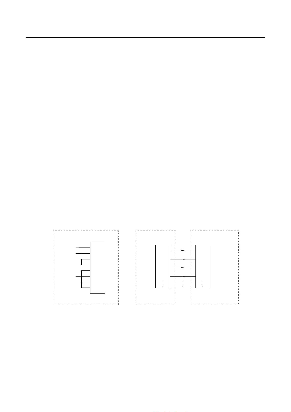
The connection of rear panel RS-232 interface is shown below, The Figure 4-1.a is
connector wire diagram of rear panel RS-232 interface, User can use the general
RS-232 cable as Figure 4-1.b.
TxD
RxD
RTS
CTS
TxD
RxD
RTS
CTS
Figure 4-1.a
TxD
RxD
RTS
CTS
DSR
GND
DCD
DTR
2
3
4
5
6
7
8
Figure 4-1.b
Inside of 3300C Mainframe RS232C port on
3300C Mainframe RS232C port on PC
9
Fig 4-1 Rs-232 INTERFACE DIAGRAM

4-2 PRODIGIT
4.3 GPIB/RS-232C COMMAND LIST
GPIB/RS-232C setting and read back command are listed in table 4-1 and 4-2。
Setting Preset numeric command Model Remark
3310A 3310C 3330A 3320 3250A
[PRESet:]BANK{SP}{d}{;|NL}9d=0~10
[PRESet:]WAVE{SP}{m}{;|NL }9M=0~4
[PRESet:]FREQuency{SP}{NR2}{;|NL}940.0~70.0Hz
[PRESet:]RISE{SP}{NR2}{;|NL}99
[PRESet:]FALL{SP}{NR2}{;|NL}99
[PRESet:]SLEWrate{SP}{NR2}{;|NL}9
[PRESet :]
SLEWRATE{SP}{FAST|MIDD|SLOW}{;|NL}9
[PRESet:]
PREIod:{HIGH|LOW}{SP}{NR2}{;|NL}999
[PRESet:]LDONv{SP}{NR2}{;|NL}99
[PRESet:]LDOFfv{SP}{NR2}{;|NL}99
[PRESet:]CC{SP}{NR2}{;|NL}99
[PRESet:]CC:{A|B}{SP}{NR2}{;|NL}9
[PRESet:]CC:{HIGH|LOW}{SP}{NR2}{ ;
|NL}999
[PRESet:]CP:{HIGH|LOW}{SP}{NR2}{ ;
|NL}9
[PRESet:]CR{SP}{NR2}{;|NL}9
[PRESet:]CR:{A|B}{SP}{NR2}{;|NL}9
[PRESet:]LIN:{A|B}{SP}{NR2}{;|NL}9
[PRESet:]CR:{HIGH|LOW}{SP}{NR2}{ ;
|NL}99
[PRESet:]CV:{HIGH|LOW}{SP}{NR2}{;
|NL}99
[PRESet:]CV{SP}{NR2}{;|NL}9
[PRESet:]
TCONFIG{SP} {NORMAL|OCP |OPP}{;|NL} 9
[PRESet:]
TCONFIG{SP} {NORMAL|OCP|OVP }{;|NL} 9
[PRESet:]OCP:START {SP} {NR2}{;|NL} 99
[PRESet:]OCP:STEP {SP} {NR2}{;|NL} 99
[PRESet:]OCP:STOP {SP} {NR2}{;|NL} 99
[PRESet:]OCP:VTH {SP} {NR2}{;|NL} 99
[PRESet:]OPP:START {SP} {NR2}{;|NL} 9
[PRESet:]OPP:STEP {SP} {NR2}{;|NL} 9
[PRESet:]OPP:STOP {SP} {NR2}{;|NL} 9
[PRESet:]OPP:VTH {SP} {NR2}{;|NL} 9
Table 4-1 GPIB/RS-232 SETTING COMMAND SUMMARY
Note:1.OCP/OPP and TCONFIG Function is available in 3310c REV:3.06 or later
Function is available in 3311c REV:3.06 or later
Function is available in 3312c REV:3.09 or later
Function is available in 3314c REV:3.07 or later
Function is available in 3315c REV:3.06 or later
Function is available in 3302c REV:2.9 or later

3302C Series Mainframe Operation Manual 4-3
Query Preset numeric command Model RETURN
3310A 3310C 3330A 3320 3250A
[PRESet:]BANK{SP}{?}{;|NL}90~10
[PRESet:]WAVE{SP}{?}{;|NL}90~4
[PRESet:]FREQuency{?}{;|NL}940.0~70.0
[PRESet:]RISE{?}{;|NL}99###.####
[PRESet:]FALL{?}{NR2}{;|NL}99###.####
[PRESet:]SLEWrate{?}{;|NL}9###.####
[PRESet:]SLEWRATE{?}{;|NL}9###.####
[PRESet:]PREIod:{HIGH|LOW}{?}{;|NL}999###.####
[PRESet:]LDONv{?}{;|NL}99###.####
[PRESet:]LDOFfv{?}{;|NL}99###.####
[PRESet:]CC{?}{;|NL}99###.####
[PRESet:]CC:{A|B}{?}{;|NL}9###.####
[PRESet:]CC:{HIGH|LOW}{?}{;|NL}999###.####
[PRESet:]CP:{HIGH|LOW}{?}{;|NL}9###.####
[PRESet:]CR{?}{;|NL}9###.####
[PRESet:]CR:{A|B}{?}{;|NL}9###.####
[PRESet:]LIN:{A|B}{?}{;|NL}9###.####
[PRESet:]CR:{HIGH|LOW}{?}{;|NL} 999###.####
[PRESet:]CV:{HIGH|LOW}{?}{;|NL} 99###.####
[PRESet:]CV{?}{;|NL} 9###.####
[PRESet:]TCONFIG {?}{;|NL} 9
1:NORMAL
2:OCP
3:3:OPP
[PRESet:]TCONFIG {?}{;|NL} 9
1:NORMAL
2:OCP
3:3:OVP
[PRESet:]OCP:START {?} {;|NL} 99###.####
[PRESet:]OCP:STEP {?}{;|NL} 99###.####
[PRESet:]OCP:STOP {?}{;|NL} 99###.####
[PRESet:]OCP:VTH {?}{;|NL} 99###.####
[PRESet:]OPP:START {?} {;|NL} 9###.####
[PRESet:]OPP:STEP {?}{;|NL} 9###.####
[PRESet:]OPP:STOP {?}{;|NL} 9###.####
[PRESet:]OPP:VTH {?}{;|NL} 9###.####
Table 4-2 GPIB/RS-232 QUERY COMMAND SUMMARY
This manual suits for next models
1
Table of contents
Other Prodigit Motherboard manuals

Popular Motherboard manuals by other brands


ASROCK
ASROCK P4VM900-SATA2 installation guide

Arbor Technology
Arbor Technology ITX-i45M2 user manual

NXP Semiconductors
NXP Semiconductors PCAL6416AEV-ARD user manual

Texas Instruments
Texas Instruments Modular MSOP8 EVM user guide

Diodes
Diodes EV1 user guide

ADLINK Technology
ADLINK Technology cPCI-3915B user manual