Prodigy Powder Spray Gun User manual

Prodigyr
Manual Powder Spray Guns
Customer Product Manual
Part 1053680E05
Issued 6/07
NORDSON CORPORATION •AMHERST, OHIO •USA
For parts and technical support, call the
Finishing Customer Support Center at (800) 433-9319.
This document is available on the Internet at http://emanuals.nordson.com/finishing
C
APPROVED
US
FM

Part 1053680E05 E2007 Nordson Corporation
Table of Contents
Safety 1. . . . . . . . . . . . . . . . . . . . . . . . . . . . . . . . . . . . . . .
Qualified Personnel 1. . . . . . . . . . . . . . . . . . . . . . . . .
Intended Use 1. . . . . . . . . . . . . . . . . . . . . . . . . . . . . .
Regulations and Approvals 1. . . . . . . . . . . . . . . . . .
Personal Safety 1. . . . . . . . . . . . . . . . . . . . . . . . . . . .
Fire Safety 2. . . . . . . . . . . . . . . . . . . . . . . . . . . . . . . .
Grounding 2. . . . . . . . . . . . . . . . . . . . . . . . . . . . . . . . .
Aggressive Substances 2. . . . . . . . . . . . . . . . . . . . .
Action in the Event of a Malfunction 3. . . . . . . . . . .
Disposal 3. . . . . . . . . . . . . . . . . . . . . . . . . . . . . . . . . .
Description 3. . . . . . . . . . . . . . . . . . . . . . . . . . . . . . . . . .
Features 3. . . . . . . . . . . . . . . . . . . . . . . . . . . . . . . . . .
Specifications 6. . . . . . . . . . . . . . . . . . . . . . . . . . . . . . .
Air Quality Requirements 6. . . . . . . . . . . . . . . . . . . .
Equipment Rating 6. . . . . . . . . . . . . . . . . . . . . . . . . .
Installation 6. . . . . . . . . . . . . . . . . . . . . . . . . . . . . . . . . .
ATEX Special Condition For Safe Use: 7. . . . . . . . .
Operation 7. . . . . . . . . . . . . . . . . . . . . . . . . . . . . . . . . . .
Presets 7. . . . . . . . . . . . . . . . . . . . . . . . . . . . . . . . . . .
Gun ON LED 7. . . . . . . . . . . . . . . . . . . . . . . . . . . . . .
Pattern Control Trigger 7. . . . . . . . . . . . . . . . . . . . . .
Maintenance 7. . . . . . . . . . . . . . . . . . . . . . . . . . . . . . . .
Nozzle Disassembly and Cleaning 8. . . . . . . . . . . .
Troubleshooting 10. . . . . . . . . . . . . . . . . . . . . . . . . . . . .
Continuity and Resistance Tests 11. . . . . . . . . . . . . .
Multiplier and Resistor Assembly
Resistance Test 11. . . . . . . . . . . . . . . . . . . . . . . . . . . .
Resistance Test - Control Cable End
to Adapter Spring Plunger 11. . . . . . . . . . . . . . . .
Resistance Test Using the Optional
Shorting Plug 11. . . . . . . . . . . . . . . . . . . . . . . . . . .
Resistor Resistance Test 12. . . . . . . . . . . . . . . . .
Control Cable Continuity Tests 12. . . . . . . . . . . . . . .
Trigger Switch Continuity Test 13. . . . . . . . . . . . . . . .
Repair 14. . . . . . . . . . . . . . . . . . . . . . . . . . . . . . . . . . . . . .
Nozzle and Powder Tube Replacement 14. . . . . . .
Control Cable Replacement 14. . . . . . . . . . . . . . . . .
Resistor and Electrode Replacement 15. . . . . . . . . .
Resistor and Electrode Removal 15. . . . . . . . . . .
Resistor and Electrode Installation 16. . . . . . . . .
Multiplier Replacement 17. . . . . . . . . . . . . . . . . . . . . .
Removal 17. . . . . . . . . . . . . . . . . . . . . . . . . . . . . . .
Assembly 17. . . . . . . . . . . . . . . . . . . . . . . . . . . . . . .
Parts 18. . . . . . . . . . . . . . . . . . . . . . . . . . . . . . . . . . . . . . .
Prodigy Manual Spray Gun - Standard Length 18.
Prodigy Manual Spray Gun - Short Length 20. . . .
Service Kits 22. . . . . . . . . . . . . . . . . . . . . . . . . . . . . . .
Options 22. . . . . . . . . . . . . . . . . . . . . . . . . . . . . . . . . . .
Powder and Air Tubing 24. . . . . . . . . . . . . . . . . . . . . .
Conical Nozzles 23. . . . . . . . . . . . . . . . . . . . . . . . . . . .
Conical Nozzle Components 23. . . . . . . . . . . . . .
Flat Spray, Cross, and Pinpoint Nozzles 24. . . . . . .
Flat Spray, Cross, and
Pinpoint Nozzle Components 25. . . . . . . . . . . . . .
Contact Us
Nordson Corporation welcomes requests for information, comments, and
inquiries about its products. General information about Nordson can be
found on the Internet using the following address:
http://www.nordson.com.
Address all correspondence to:
Nordson Corporation
Attn: Customer Service
555 Jackson Street
Amherst, OH 44001
Notice
This is a Nordson Corporation publication which is protected by copyright.
Original copyright date 2004. No part of this document may be
photocopied, reproduced, or translated to another language without the
prior written consent of Nordson Corporation. The information contained
in this publication is subject to change without notice.
Trademarks
Prodigy, HDLV, Nordson, and the Nordson logo are registered trademarks
of Nordson Corporation.
Viton is a registered trademark of DuPont Dow Elastomers. L.L.C.

ProdigyrManual Powder Spray Gun 1
Part 1053680E05
E2007 Nordson Corporation
ProdigyrManual Powder Spray Gun
Safety
Read and follow these safety instructions. Task-
and equipment-specific warnings, cautions, and
instructions are included in equipment
documentation where appropriate.
Make sure all equipment documentation, including
these instructions, is accessible to all persons
operating or servicing equipment.
Qualified Personnel
Equipment owners are responsible for making sure
that Nordson equipment is installed, operated, and
serviced by qualified personnel. Qualified
personnel are those employees or contractors who
are trained to safely perform their assigned tasks.
They are familiar with all relevant safety rules and
regulations and are physically capable of
performing their assigned tasks.
Intended Use
Use of Nordson equipment in ways other than
those described in the documentation supplied with
the equipment may result in injury to persons or
damage to property.
Some examples of unintended use of equipment
include
Susing incompatible materials
Smaking unauthorized modifications
Sremoving or bypassing safety guards or
interlocks
Susing incompatible or damaged parts
Susing unapproved auxiliary equipment
Soperating equipment in excess of maximum
ratings
Regulations and Approvals
Make sure all equipment is rated and approved for
the environment in which it is used. Any approvals
obtained for Nordson equipment will be voided if
instructions for installation, operation, and service
are not followed.
All phases of equipment installation must comply
with all federal, state, and local codes.
Personal Safety
To prevent injury follow these instructions.
SDo not operate or service equipment unless you
are qualified.
SDo not operate equipment unless safety
guards, doors, or covers are intact and
automatic interlocks are operating properly. Do
not bypass or disarm any safety devices.
SKeep clear of moving equipment. Before
adjusting or servicing any moving equipment,
shut off the power supply and wait until the
equipment comes to a complete stop. Lock out
power and secure the equipment to prevent
unexpected movement.
SRelieve (bleed off) hydraulic and pneumatic
pressure before adjusting or servicing
pressurized systems or components.
Disconnect, lock out, and tag switches before
servicing electrical equipment.
STo prevent injury, be aware of less-obvious
dangers in the workplace that often cannot be
completely eliminated, such as hot surfaces,
sharp edges, energized electrical circuits, and
moving parts that cannot be enclosed or
otherwise guarded for practical reasons.
SObtain and read Material Safety Data Sheets
(MSDS) for all materials used. Follow the
manufacturer’s instructions for safe handling
and use of materials, and use recommended
personal protection devices.

ProdigyrManual Powder Spray Gun
2
Part 1053680E05 E2007 Nordson Corporation
Fire Safety
To avoid a fire or explosion, follow these
instructions.
SDo not smoke, weld, grind, or use open flames
where flammable materials are being used or
stored.
SProvide adequate ventilation to prevent
dangerous concentrations of volatile materials
or vapors. Refer to local codes or your material
MSDS for guidance.
SDo not disconnect live electrical circuits while
working with flammable materials. Shut off
power at a disconnect switch first to prevent
sparking.
SKnow where emergency stop buttons, shutoff
valves, and fire extinguishers are located. If a
fire starts in a spray booth, immediately shut off
the spray system and exhaust fans.
SClean, maintain, test, and repair equipment
according to the instructions in your equipment
documentation.
SUse only replacement parts that are designed
for use with original equipment. Contact your
Nordson representative for parts information
and advice.
Grounding
WARNING: Operating faulty
electrostatic equipment is hazardous and
can cause electrocution, fire, or
explosion. Make resistance checks part
of your periodic maintenance program. If
you receive even a slight electrical shock
or notice static sparking or arcing, shut
down all electrical or electrostatic
equipment immediately. Do not restart
the equipment until the problem has
been identified and corrected.
Grounding inside and around the booth openings
must comply with NFPA requirements for Class II,
Division 1 or 2 Hazardous Locations. Refer to
NFPA 33, NFPA 70 (NEC articles 500, 502, and
516), and NFPA 77, latest conditions.
SAll electrically conductive objects in the spray
areas shall be electrically connected to ground
with a resistance of not more than 1 megohm
as measured with an instrument that applies at
least 500 volts to the circuit being evaluated.
SEquipment to be grounded includes, but is not
limited to, the floor of the spray area, operator
platforms, hoppers, photoeye supports, and
blow-off nozzles. Personnel working in the
spray area must be grounded.
SThere is a possible ignition potential from the
charged human body. Personnel standing on a
painted surface, such as an operator platform,
or wearing non-conductive shoes, are not
grounded. Personnel must wear shoes with
conductive soles or use a ground strap to
maintain a connection to ground when working
with or around electrostatic equipment.
SOperators must maintain skin-to-handle contact
between their hand and the gun handle to
prevent shocks while operating manual
electrostatic spray guns. If gloves must be
worn, cut away the palm or fingers, wear
electrically conductive gloves, or wear a
grounding strap connected to the gun handle or
other true earth ground.
SShut off electrostatic power supplies and
ground gun electrodes before making
adjustments or cleaning powder spray guns.
SConnect all disconnected equipment, ground
cables, and wires after servicing equipment.
Aggressive Substances
If the equipment is likely to come into contact with
aggressive substances, then it is the responsibility
of the user to take suitable precautions that prevent
it from being adversely affected, thus ensuring that
the type of protection provided by the equipment is
not compromised.
Aggressive substances: e.g. acidic liquids or
gases that may attack metals, or solvents that may
affect polymeric materials.
Suitable precautions: regular check as part of
routine inspections or establishing from the
material’s data sheets that it is resistant to specific
chemicals.
Please contact Nordson Corporation if you are
concerned or unsure about the suitability of the
product with relation to coming into contact with
particularly aggressive substances.
ProdigyrManual Powder Spray Gun 3
Part 1053680E05
E2007 Nordson Corporation
Action in the Event of a Malfunction
If a system or any equipment in a system
malfunctions, shut off the system immediately and
perform the following steps:
SDisconnect and lock out electrical power. Close
pneumatic shutoff valves and relieve pressures.
SIdentify the reason for the malfunction and
correct it before restarting the equipment.
Disposal
Dispose of equipment and materials used in
operation and servicing according to local codes.
Description
The Prodigy Manual Powder Spray Guns use
specially designed conical and flat-spray nozzles to
atomize, shape, and spray dense-phase powder
delivered by Nordson HDLVr(high-density powder,
low-velocity air) pumps.
The spray gun is available in a standard length and
a short length.
Features
S8-mm tubing used for powder delivery
SSeparate high voltage and powder paths.
SSpecial pattern control trigger toggles between
user-programmable high and low pattern air
and powder flows.
SShipped with a 70_conical nozzle and a
dual-slot flat-spray nozzle. Optional conical, flat
spray, cross, and pinpoint nozzles are available.
SUser-friendly controller with LCD display.
SUp to 10 user-programmable coating recipes.
1
2
3
45
6
78
9
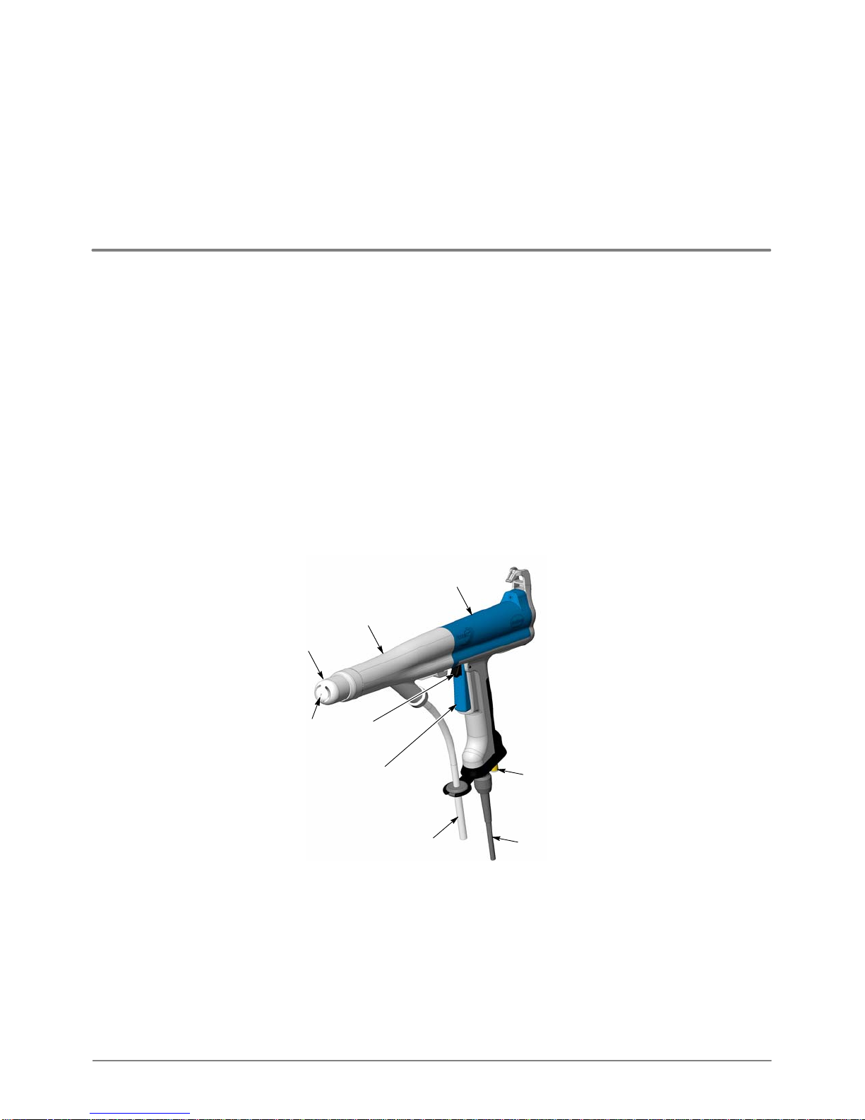
Figure 1 Prodigy Manual Powder Spray Gun
1. Gun body
2. Adapter
3. Conical nozzle
4. Nozzle electrode
5. Pattern control trigger
6. Trigger
7. Powder tubing (8 mm)
8. Control cable
9. Pattern air fitting (6 mm)
Note: Powder and pattern air tubing are not shipped with the spray gun. Tubing is included in manual gun systems.

ProdigyrManual Powder Spray Gun
4
Part 1053680E05 E2007 Nordson Corporation
Description (contd)
1
23
22
54
76
8
9
10
11
15
21
18
12
17
16
13
14
19
2
20
1/2in.
18 19 14
24
3
PRODIGY
NORDSON CORPORATION
SIRA05ATEX5212X EEx 2mJ
1180 II 2D
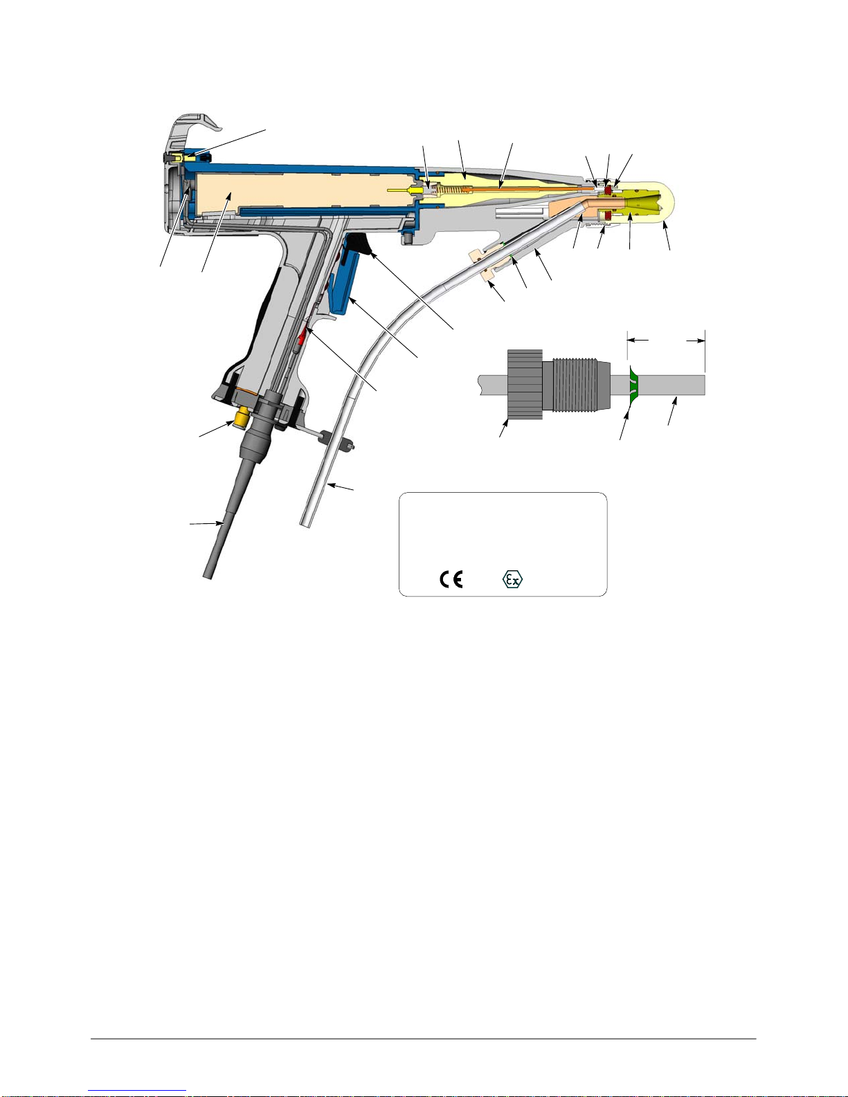
Figure 2 Standard Length Spray Gun Section View
1. Nozzle electrode*
2. Nozzle electrode ring*
3. Spring plunger
4. Electrode
5. Electrode holder
6. Resistor
7. Resistor holder
8. Contact spacer
9. Voltage multiplier
10. Ground stud
11. Cable/multiplier connection
12. 6-mm tube fitting (pattern air)
13. Control cable
14. 8-mm powder tubing
15. Switch keypad
16. Spray trigger
17. Pattern control trigger
18. Lock knob
19. Grip ring
20. Adapter
21. Powder tube
22. Retainer nut
23. Nozzle Insert*
24. Nozzle*
Note: Parts marked with an asterisk (*) are part of the nozzle assembly. Powder and pattern air tubing are included with
manual gun systems only.
ProdigyrManual Powder Spray Gun 5
Part 1053680E05
E2007 Nordson Corporation
PRODIGY
NORDSON CORPORATION
SIRA05ATEX5212X EEx 2mJ
1180 II 2D
23
22
76
8
10
15
21
18
12
17
16
13
14
19 20
18 14
24
11 9
1/2in.
19
1
2
3
Figure 3 Short Length Spray Gun Section View
Note: Use the legend from Figure 2 for the numbered components.

ProdigyrManual Powder Spray Gun
6
Part 1053680E05 E2007 Nordson Corporation
Specifications
Specifications are subject to change without notice.
Electrical Output
Maximum rated output voltage at the electrode: 95 kV ±10%
Maximum rated output current at the electrode: 100 µA ±10%
Air Pressure and Flow Requirements
Minimum input air: 4 bar (60 psi)
Maximum input air: 6.9 bar (100 psi)
Pattern air: 5.9 bar (85 psi), 6-57 l/min. (0.2-2.0 scfm)
Temperature Requirements
Maximum ambient temperature 40 _C (104 _F)
Air Quality Requirements
Powder spray systems require clean, dry, oil-free
compressed air. Moist or oil-contaminated air can
cause the powder to clog in the pump, powder feed
tubing, or spray gun.
Use 3-micron filter/separators with automatic drains
and a refrigerated or regenerative desiccant-type
air dryer that can produce a 3.4 _C (38 _F) or lower
dewpoint at 6.9 bar (100 psi).
Equipment Rating
This applicator is rated for use in a potentially
explosive environment: Class II, Division I, Group
F & G, Zone 21 or Zone 22.
Installation
WARNING: Allow only qualified
personnel to perform the following tasks.
Follow the safety instructions in this
document and all other related
documentation.
WARNING: Installation in Europe shall
carried out by suitably trained personnel
in accordance with the applicable code of
practice. EN60079-14
See Figure 2.
1. Connect the control cable (13) to the gun
controller receptacle labeled GUN and tighten
the cable nut securely.
NOTE: Refer to page 22 for optional
four-meter extension cables. Do not use more
than two extension cables.
NOTE: Powder and pattern air tubing are supplied
only with manual gun systems or can be ordered
separately. Refer to page 22 for tubing part
numbers.
2. Connect blue 6-mm pattern air tubing from the
appropriate pattern air outlet fitting on the pump
control cabinet to the tube fitting (12) on the
gun handle.
3. Use a tubing cutter to cut the 8-mm powder
delivery and suction tubing to the desired
lengths. The ends must be square. Refer to
page 22 for an optional tubing cutter.
Delivery tubing (pump to gun)
Minimum length: 9 m (30 ft)
Maximum length: 32 m (75 ft)
Suction tubing (pump to powder supply)
Minimum length: 1 m (3.5 ft)
Maximum length: 3.65 m (12 ft)
4. Push one end of the powder delivery tubing
through the grommet in the tubing bracket, then
install the lock knob (18) on the tubing (14).
5. Install a grip ring (19) 12.7-mm (1/2-in.) from the
end of the delivery tubing.
ProdigyrManual Powder Spray Gun 7
Part 1053680E05
E2007 Nordson Corporation
Installation (contd)
6. Push the delivery tubing into the adapter (20)
until it bottoms out against the powder tube
(21). Thread the lock knob into the adapter and
finger-tighten it until snug.
7. Route the delivery tubing to the appropriate
powder pump. Remove the outlet fitting (rear
fitting) and O-ring and install them on the
tubing, then screw the fitting back onto the
pump.
8. Connect suction tubing as described in the
powder pump manual or Color-on-Demand
installation manual.
9. Use cable ties or spiral-cut tube wrap to bundle
together the gun control cable, pattern air
tubing, and powder tubing.
ATEX Special Condition For Safe Use:
This applicator shall only be used with the Prodigy
Manual Controller.
Operation
WARNING: This equipment can be
dangerous unless it is used in
accordance with the rules laid down in
this manual.
All gun functions are set and controlled by the
manual gun controller.
Presets
A preset is a group of spray settings. The gun
controller provides 10 presets. Use the presets to
save optimal spray settings for parts with different
features.
Gun ON LED
The LED on the end plate lights when the spray
trigger is pulled and high voltage is generated.
Pattern Control Trigger
The pattern control trigger toggles between the
preset settings (High mode) and the Low mode
settings. Use it to change the pattern air and
powder flow as needed when part features change.
When in Low mode, a down-pointing arrow (⇓) is
appears to the right of the gun icon.
NOTE: If you change presets while spraying in
Low mode, the controller immediately switches to
High mode, spraying with the new preset settings.
Maintenance
WARNING: Inspection and maintenance
of this equipment in Europe shall carried
out by suitably trained personnel in
accordance with the applicable code of
practice. EN60079-17
Daily: Blow off the gun exterior with low-pressure
compressed air and wipe it clean with a soft cloth.
Weekly: Manually perform a hard purge, then
remove the retaining nut, nozzle, and powder tube.
Inspect the powder tube and nozzle for wear.
Replace any worn parts.
Periodically: Check the resistance of the voltage
multiplier and resistor with a megohm meter as
described in Continuity and Resistance Checks on
page 11. Replace any components that do not
meet the specifications.
As Required: Disassemble the nozzle and clean
the internal parts. Replace any worn parts. Refer
to Nozzle Disassembly and Cleaning on the
following page for instructions.
ProdigyrManual Powder Spray Gun
8
Part 1053680E05 E2007 Nordson Corporation
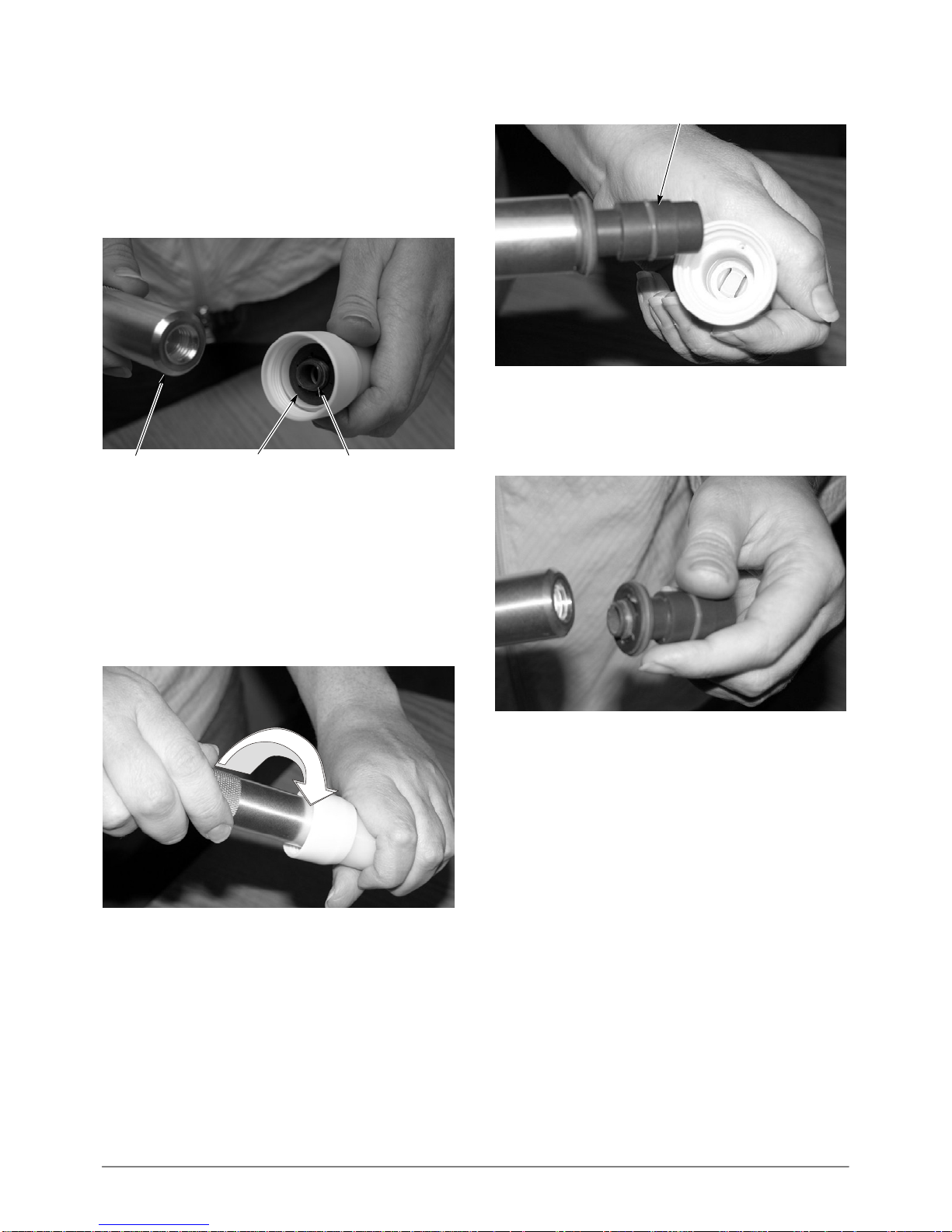
Nozzle Disassembly and Cleaning
Requirements: Nozzle Tool 1073682
1. Hold the nozzle firmly in one hand. Thread the
tool onto the threaded end of the insert until it
bottoms out on the electrode ring.
Insert
Electrode Ring
Tool
Figure 4 Nozzle Disassembly Step 1 (Shown with Nut
Installed)
2. Turn the tool clockwise while pulling on it until
the electrode ring/insert assembly comes out of
the nozzle.
NOTE: If the electrode is pulled out of the nozzle
shell, be careful to not lose it. The dual slot nozzle
has the electrode glued in.
Figure 5 Nozzle Disassembly Step 2A
Electrode Ring/Insert Assembly
Figure 6 Nozzle Disassembly Step 2B (New Style
Assembly Shown)
3. Unscrew the tool from the electrode ring/insert
assembly and blow off the assembly with
compressed air.
Figure 7 Nozzle Disassembly Step 3 (New Style
Shown)
4. Place the nozzle and nozzle nut in an ultrasonic
cleaner to remove any impact fusion, then blow
them off with compressed air. If desired,
remove the nozzle nut from the nozzle by
sliding the nut forward then turning it clockwise
to unscrew it.
NOTE: See Figure 9. Old style nozzles have a
disk-shaped filter (3) installed on the outside of the
insert (6) and held on by the electrode ring (2).
New style nozzles have a conical filter that is
installed inside the front end of the insert. The old
style filter and insert are obsolete. if you are
replacing the filter on an old style nozzle, you must
also order a new insert. The new filters are
available in quantities of 10.

ProdigyrManual Powder Spray Gun 9
Part 1053680E05
E2007 Nordson Corporation
5. Blow off the insert and filter. If the filter is
clogged with powder, remove it and replace it
with a new one. When removing the new style
filter from the insert, be careful not to scratch
the inside surface of the insert.
To re-assemble the nozzle:
1. Make sure the electrode ring is threaded all the
way onto the insert.
2. Thread the tool onto the threaded end of the
insert.
3. Turn the tool counterclockwise to remove it
from the insert. Check the nozzle. The
electrode ring should be approximately 1/4inch
inside the nozzle lip.
Electrode Ring
Nozzle Lip
Figure 8 Nozzle Re-assembly
7
6
5
4
3
2
1
OLD STYLE NOZZLE COMPONENTS
12
3
45
7
6
NEW STYLE NOZZLE COMPONENTS
8
8
Figure 9 Internal Components of Nozzle Assemblies
1. O-ring
2. Electrode ring
3. Filter
4. O-ring
5. O-ring
6. Insert
7. Electrode
8. Nozzle shell
Note: All internal components, except the electrodes, are the same for all nozzles. For flat-spray, cross, and pinpoint
nozzles, the electrode is glued into the nozzle shell with epoxy and cannot be replaced separately.

ProdigyrManual Powder Spray Gun
10
Part 1053680E05 E2007 Nordson Corporation
Troubleshooting
WARNING: Allow only qualified
personnel to perform the following tasks.
Follow the safety instructions in this
document and all other related
documentation.
These procedures cover only the most common
problems that you may encounter. If you cannot
solve the problem with the information given here,
contact your local Nordson representative for help.
Problem Possible Cause Corrective Action
1. Unsteady or
inadequate powder
flow
Problem with powder pump Refer to pump manual for
troubleshooting.
Blockage in powder tubing Perform a hard purge to clear tubing.
Replace tubing if partially or
completely blocked.
Plugged nozzle Remove nozzle and clean.
2. Uneven pattern Insufficient pattern air flow Increase pattern air flow.
Worn powder tube Remove powder tube from gun and
check for worn passageway.
3. Loss of wrap, poor
transfer efficiency Low electrostatic voltage Increase the electrostatic voltage (kV
or µA setting).
Poorly grounded parts Check the conveyor chain, rollers,
and part hangers for powder buildup.
The resistance between the parts
and ground must be 1 megohm or
less. For best results, 500 ohms or
less is recommended.
Poor connection in high voltage
path inside spray gun Perform the Multiplier and Resistor
Assembly Resistance Tests on
page 11.
Fault in controller Refer to Troubleshooting in the gun
controller manual.
4. No kV output from the
spray gun (LED on
the spray gun does
not light)
Damaged control cable Perform the control cable continuity
tests on page 12.
If an open or short is found, replace
the cable.
Fault in controller Refer to Troubleshooting in the gun
controller manual.
5. No kV output from the
spray gun (LED on
the spray gun lights)
Faulty voltage multiplier or poor
connection in high voltage path
inside spray gun
Perform the resistance tests on
page 11.
Check all high voltage path
connections.
6. No kV output and no
powder output Faulty trigger switch or control
cable Perform the control cable continuity
tests on page 12, and the trigger
switch test on page 13.
Faulty controller wiring harness Check the wiring between the GUN
receptacle and the circuit board.
Faulty controller circuit board Check the circuit board as described
in the controller manual.

ProdigyrManual Powder Spray Gun 11
Part 1053680E05
E2007 Nordson Corporation
Continuity and Resistance Tests
WARNING: Turn off the electrostatic
voltage and ground the spray gun
electrode before performing the following
tasks. Failure to observe this warning
could result in a severe shock.
Use the following tests to isolate problems with the
voltage multiplier or resistor, control cable, and
trigger switch.
Multiplier and Resistor Assembly
Resistance Test
Resistance tests must be made with a 500 volt
megohm meter.
CAUTION: Short together the three pins
in the multiplier receptacle, or the
designated pins in the control cable,
before testing the continuity and
resistance of the
multiplier/resistor/electrode assembly. If
not shorted, the multiplier could be
damaged.
Use the optional shorting plug shown in Figure 11
when testing resistance from the multiplier
receptacle to the adapter spring plunger. Refer to
Options in Parts for the shorting plug part number.
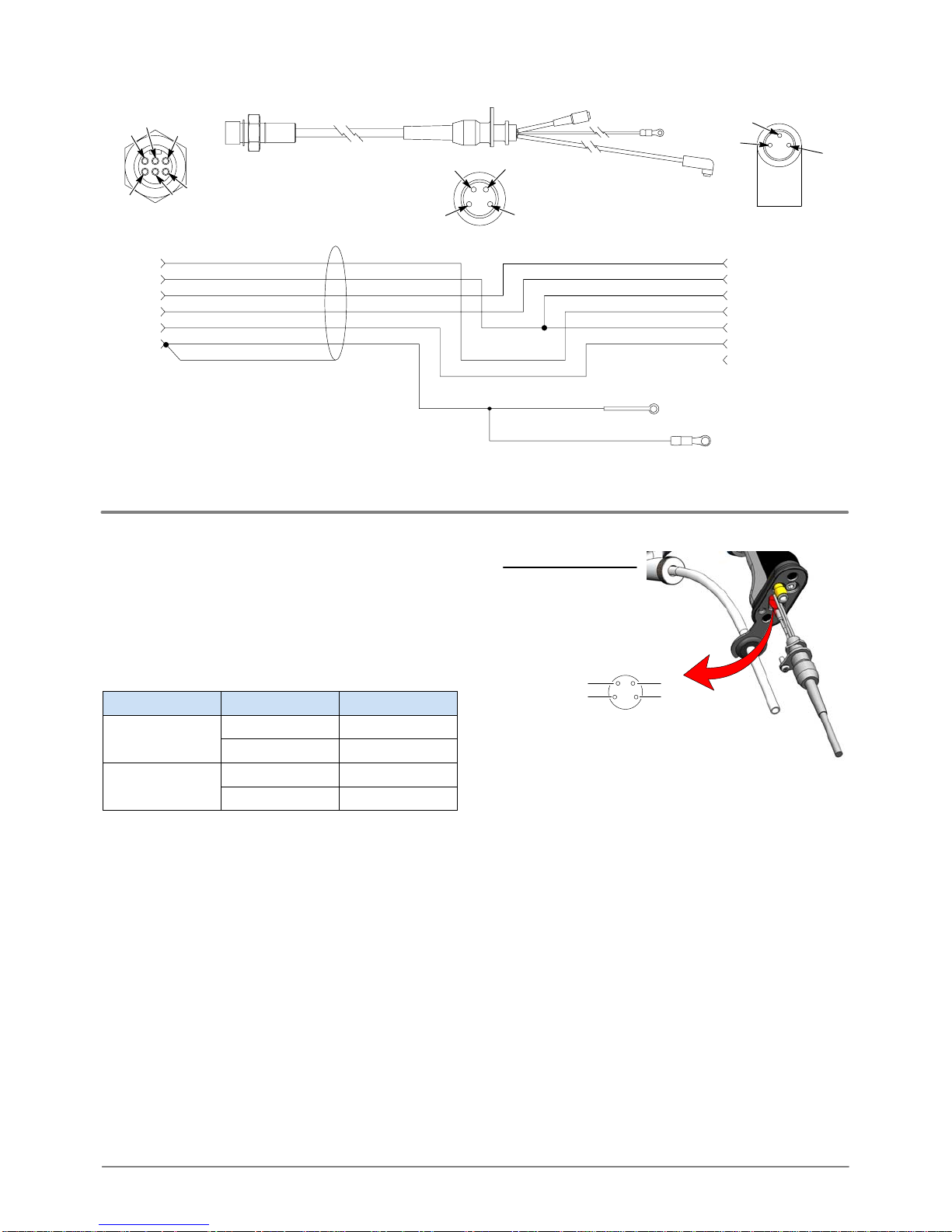
Resistance Test - Control Cable End to
Adapter Spring Plunger
1. See Figure 10. Remove the nozzle.
2. Disconnect the control cable from the manual
control unit.
3. Short together cable connector pins J1-2, J1-3,
and J1-4 and connect them to the positive
megohm meter probe.
4. Connect the negative megohm meter probe to
the adapter spring plunger.
The megohm meter reading should be
350-420 megohms. If the reading is out of this
range, test the resistor separately. If the resistor
passes the test, replace the multiplier.
Pin 2 Pin 3
Pin 4
350-420
megohms
Figure 10 Cable End to Spring Plunger Test
Resistance Test Using the
Optional Shorting Plug
1. See Figure 11. Remove the end cap and
nozzle from the spray gun.
2. Disconnect the multiplier connector from the
multiplier receptacle.
3. Connect the shorting plug connector to the
multiplier receptacle.
4. Connect the megohm meter positive probe to
the shorting plug ring-tong terminal and the
negative probe to the spring plunger. (If the
reading is infinite, switch the probes).
5. The megohm meter should read
350-420 megohms. If the reading is out of this
range, test the resistor separately. If the
resistor passes the test, replace the multiplier.

ProdigyrManual Powder Spray Gun
12
Part 1053680E05 E2007 Nordson Corporation
Resistance Test Using the Optional Shorting Plug (contd)
Shorting Plug
350-420
megohms
Figure 11 Test with Shorting Plug
Resistor Resistance Test
1. Remove the resistor/electrode assembly as
described in Resistor and Electrode
Replacement on page 15.
2. See Figure 12. Connect the megohm meter
probes to the resistor spring and electrode
spring.
The megohm meter reading should be
153-187 megohms. If it is out of this range,
replace the resistor. If it is within this range, but the
multiplier/resistor resistance check was out of
range, replace the multiplier.
153-187
megohms
Figure 12 Resistor Resistance Test
Control Cable Continuity Tests
Make continuity tests with a standard ohmmeter.
Use the following table and Figure 13.
NOTE: The first two tests in the following table can
be made by disconnecting the cable from the
manual control unit. All other tests require
disconnecting the J2, J3, and ground connectors
from the gun as described in Cable Replacement
on page 14.
Test for continuity between:
J1 pins 1 and 2, spray trigger pressed
J1 pins 2 and 5, pattern air trigger pressed
J1 pin 1 and J3 pin 1
J1 pin 2 and J2 pin 3 and J3 pin 2
J1 pin 3 and J2 pin 1
J1 pin 4 and J2 pin 2
J1 pin 5 and J3 pin 3
J1 pin 6 and ground terminal
ProdigyrManual Powder Spray Gun 13
Part 1053680E05
E2007 Nordson Corporation
J3
J2
J1
123
4
5
6
12
3
42
1
3
J1 J2
J3
Ground
(N/C)
J1-1
J1-2
J1-3
J1-4
J1-5
J1-6 J3-4
J3-3
J3-2
J3-1
J2-1
J2-3
J2-2
SPRAY TRIGGER +
COMMON
+VDC
uA FEEDBACK
PATTERN TRIGGER +
GND
SHIELD
CABLE GND
IC WIRE
MOLDED INTO
STRAIN RELIEF
+VDC
uA FEEDBACK
COMMON
SPRAY TRIGGER +
COMMON
PATTERN TRIGGER +
Figure 13 Control Cable Continuity Tests
Trigger Switch Continuity Test
Disconnect the control cable from the trigger
switch, as described in Cable Replacement on
page 14.
Test for continuity using the following table and
Figure 14.
Pins Trigger Results
1 and 2
Off (Open) No continuity
1 and 2 On (Closed) Continuity
2 and 3
Off (Open) No continuity
2 and 3 On (Closed) Continuity
Pin
2
14
3
J3
1 Spray Trigger
2 Common
3 Pattern Control Trigger
4 N/C
Function
Figure 14 Trigger Switch Continuity Test

ProdigyrManual Powder Spray Gun
14
Part 1053680E05 E2007 Nordson Corporation
RepairWARNING: Allow only qualified
personnel to perform the following tasks.
Follow the safety instructions in this
document and all other related
documentation.
WARNING: Turn off the electrostatic
voltage and ground the spray gun
electrode before performing the following
tasks. Failure to observe this warning
could result in a severe shock.
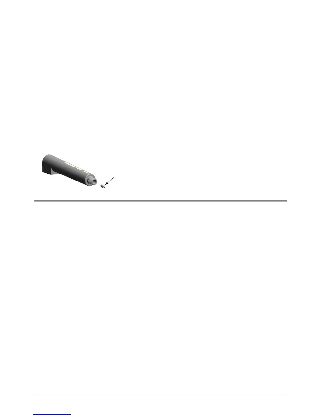
Nozzle and Powder Tube Replacement
1. Shut off the controller power switch.
2. See Figure 15. Unscrew the lock knob (7) and
pull the powder tubing out of the adapter (9).
7
9
Figure 15 Disconnecting the Powder Tubing
3. See Figure 16. Unscrew the retaining nut (12)
and remove it from the spray gun.
4. Unscrew the nozzle (11) from the retaining nut.
5. Pull the powder tube (10) out of the adapter.
12
11
10
Short gun powder tube
Standard gun
powder tube
Figure 16 Removing the Air Cap and Powder Tube
6. Slide a new powder tube into the adapter.
7. Screw the nozzle back into the retaining nut,
then install the nozzle onto the powder tube and
screw the retaining nut back onto the adapter.
8. See Figure 15. Push the powder tubing into the
adapter until it bottoms out against the powder
tube. Screw the lock knob into the adapter and
tighten until snug.
Control Cable Replacement
1. Shut off the gun controller power switch and
remove the powder tubing from the gun. Refer
to step 2 of Nozzle and Powder Tube
Replacement.
2. Remove the gun from the spray area (at least
one meter (3 ft) from the spray booth).
3. See Figure 17. Remove the screw (36)
securing the cable (37) to the bottom of the gun
handle.
4. Rotate the cable to release it from the handle
base. Gently pull down on the cable until you
can grasp the trigger switch receptacle (28).
5. Disconnect the trigger cable plug (J3) from the
trigger switch receptacle.
28
37
36
J3
Figure 17 Disconnecting the Control Cable from the
Handle

ProdigyrManual Powder Spray Gun 15
Part 1053680E05
E2007 Nordson Corporation
Control Cable Replacement (contd)
6. See Figure 18. Remove the end cap
screw (21) and end cap (20) from the gun body.
20
2121
Figure 18 Removing the End Cap
7. See Figure 19. Disconnect the multiplier
connector (J2) from the multiplier receptacle.
8. Remove the post and lock washer (17, 16) to
disconnect the ground terminal (GND).
J2
GND
17
16
Figure 19 Disconnecting the Control Cable
9. See Figure 20. Lift up on the back of the gun
body (14) to unsnap it from the handle, then
push the body forward to separate it from the
handle (23).
Feed cable
through here
14
23
Figure 20 Separating the Gun Body from the Handle
10. Feed the ground and multiplier wiring through
the opening in the handle.
11. Perform the previous steps in reverse to install
a new cable.
Resistor and Electrode Replacement
Resistor and Electrode Removal
1. See Figure 15. Unscrew the lock knob (7) and
pull the powder tubing out of the adapter (9).
2. See Figure 21. Loosen the set screw (5) in the
bottom on the adapter.
5
9
Figure 21 Loosening the Adapter Set Screw

ProdigyrManual Powder Spray Gun
16
Part 1053680E05 E2007 Nordson Corporation
Resistor and Electrode Removal (contd)
3. See Figure 22. Pull the adapter (9) straight off
the gun body (14).
14
9
Short length spray gun
Standard length spray gun
Figure 22 Removing the Adapter
4. See Figure 23. Unscrew the resistor holder (3)
from the multiplier (19).
3
19 Short length resistor holder
Standard length resistor holder
Figure 23 Removing the Resistor Holder
5. See Figure 24. Remove the contact
spacer (18) from the multiplier well. Wipe the
dielectric grease off the contact spacer.
Multiplier Well
18
Figure 24 Removing the Contact Spacer
6. See Figure 25. Remove the resistor (4) from
the resistor holder (3). Clean the resistor
holder.
43
Resistor Well
Figure 25 Removing the Resistor from the Holder
7. See Figure 26. Standard Length only: To
replace the electrode (2), pull it out of the
electrode holder (1).
2
1
Figure 26 Replacing Electrode
Clean and inspect the resistor holder and electrode
holder. Replace the holders If you find carbon
tracks or pin holes in them.
Resistor and Electrode Installation
1. See Figure 26. If removed, install the electrode
in the electrode holder, then thread the
electrode holder into the resistor holder.
2. See Figure 25. Inject approximately 0.60 cc of
dielectric grease into the resistor well.
3. Insert the resistor into the resistor holder until it
bottoms out, then fill the resistor well with
approximately 0.8 cc of dielectric grease.
4. See Figure 24. Insert the contact spacer into
the multiplier well. Fill the multiplier well with
dielectric grease.
5. See Figure 23. Screw the resistor holder onto
the multiplier.
6. See Figures 22 and 21. Install the adapter on
the gun body. Tighten the set screw.
7. See Figure 15. Push the powder tubing into the
adapter until it bottoms out against the powder
tube. Screw the lock knob into the adapter and
tighten it snugly.
ProdigyrManual Powder Spray Gun 17
Part 1053680E05
E2007 Nordson Corporation
Multiplier Replacement
Removal
1. Remove the resistor holder. Refer to steps 1-4
of the Resistor and Electrode Replacement
procedure.
2. Remove the end cap and disconnect the control
cable. Refer to steps 6-8 of the Control Cable
Replacement procedure.
3. Push the multiplier out of the gun body from the
front.
4. See Figure 27. Remove the contact spacer
(18) from the multiplier well. Clean the
dielectric grease off the contact spacer.
18
Figure 27 Removing the Contact Spacer
Assembly
1. See Figure 27. Insert the contact spacer into
the multiplier well. Fill the multiplier well with
dielectric grease.
2. Install the multiplier into the gun body.
3. Fill the resistor holder well with dielectric
grease. Refer to Resistor and Electrode
Installation instructions.
4. See Figure 23. Screw the resistor holder onto
the multiplier.
5. See Figures 22 and 21. Install the adapter over
the electrode and resistor holders. Tighten the
set screw.
6. See Figure 19. Connect the ground wire to the
gun body with the lockwasher and post.
Connect the multiplier connector (J3) to the
multiplier receptacle.
7. See Figure 18. Install the end cap on the gun
body with the screw.
8. See Figure 15. Push the powder tubing into the
adapter until it bottoms out against the powder
tube, then thread the lock knob into the adapter
and tighten it snugly.

ProdigyrManual Powder Spray Gun
18
Part 1053680E05 E2007 Nordson Corporation
Parts
Prodigy Manual Spray Gun - Standard Length
Item Part Description Quantity Note
— 1053594 GUN, manual, 95 kV, Prodigy 1
1 1010561 SHOLDER, electrode, M4 1
2 1064038 SELECTRODE, spring contact, 0.154 diameter 1
3 1049605 SHOLDER, resistor, Prodigy, manual 1
4 1053912 SKIT, resistor, cable, series 1
5 982455 SSCREW, set, M6 x 1 x 8, nylon, black 1
6 1047796 SGRIP RING, 8 mm, TE 1 A
7 1047934 SKNOB, lock, powder tube 1
8 940117 SO-RING, silicone, 0.312 x 0.438 x 0.063 in. 3
9 1053897 SKIT, adapter/spring plunger assembly 1 C
10 1049603 SPOWDER TUBE, Prodigy manual 1
11 1062223 SKIT, nozzle, 70 degree, conical 1 B
12 1047536 SNUT, retaining 1
13 940212 SO-RING, silicone, 0.938 x 1.063 x 0.063 in. 1
14 1053683 SBODY, handgun, Prodigy 1
15 288815 SRIVET, snap, 0.125 in. diameter, black, Nylon 1
16 983416 SWASHER, lock, internal, M4, steel, zinc 1
17 288553 SPOST, spacer, hex 1
18 1053595 SSPACER, contact 1
19 288552 SPOWER SUPPLY, 95 kV, negative 1 C
20 - - - - - - SCAP, end, handgun 1
21 982800 SSCREW, pan, recessed, M4 x 6, black, zinc 1
22 1069680 SGASKET, cover, handgun 1
23 288561 SHANDLE, w/cover, handgun 1
23A 288534 SS GASKET, base, hand gun 1
24 288541 STRIGGER, purge, handgun 1
25 288542 STRIGGER, actuator, handgun 1
26 288537 SPIVOT, threaded, gun, M5 1
27 288549 SSWITCH, keypad, trigger/purge 1
28 288550 SPAD, ground, small, handgun 1 C
29 288538 SBASE, handle, handgun 1
30 1062113 SGROMMET, Buna-N, 0.312 ID x 1.00 in. OD 1
31 288545 SBRACKET, hose, handgun 1
32 982801 SSCREW, oval, recessed, M4 x 20, black, zinc 2
33 328524 SCONNECTOR, male, w/integral hex, 6 mm
tube x M5 1
34 973402 SPLUG, pipe, socket, flush, 1/8in. NPT, zinc 1
35 982825 SSCREW, pan head, rec, M4 x 12, with integral
lock washer bezel, black, zinc 1
36 1053914 SKIT, cable, handgun, Prodigy, 6 meter 1
37 1073706 SKIT, nozzle, flat spray, dual slot, converging
angle, 1 mm 1 B
NOTE A: Also available in packages of 10. Refer to page 22 for service kits.
B: Refer to page NO TAG for conical nozzles and components; pages NO TAG and 25 for flat spray, cross,
and pinpoint nozzles and components.
C: Refer to page 22 for options.
NS: Not Shown
Table of contents


