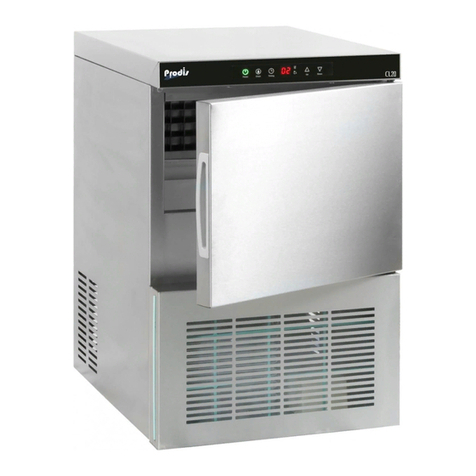
PRODIS CL20 User manual

CL20
ICE MAKER
ICE MAKER
CL161019SM Rev 1.0
SERVICE MANUAL

PART I - ERROR CODES & EXPLANATIONS
PART II - MAINTENANCE
PART III - TECHNICAL DATA
PART IV - SPARE PARTS DIAGRAM & LIST
PART V - WIRING DIAGRAM
TABLE OF CONTENTS
CL161019SM Rev 1.0

PART I
Error
Code Description Solution
E1 Water Shortage Check mains water pressure is between 1.4 - 5.5 bar
Check mains water supply is connected and turned on
Check for kinks or blockages in mains water supply line externally
replace where necessary
Check for kinks or blockages in mains water supply line internally,
replace where necessary
Check oat valve for operation, replace where necessary
E2 Harvest Overtime Refer to page 2
E3 Condenser sensor open
circuit
Check condenser sensor connection, replace where necessary
E4 Evaporator sensor open
circuit
Check Evaporator sensor connection, replace where necessary
E5 Ambient sensor open
circuit
Check Ambient sensor connection, replace where necessary
E6 Evaporator over tempera-
ture protection
Evaporator too hot, check hot gas valve, replace where necessary
E7 Ambient temperature out
of range
Ice maker is located in a room with too high or too low ambient, relo-
cate ice maker in a room with a temperature range of +10°c to +32°c
E8 Ice production over time Ice production has taken too long, allow sucient time for ice to fall
from the evaporator plate,
do not try to manually remove the ice from the evaporator.
Check ambient air temperature is within operating range of +10°c to
+32°c.
Check incoming water temperature is within operation range of +7°c
to +32°c.
Check hot gas valve for operation, replace where necessary
1CL161019SM Rev 1.0
ERROR CODES

2
CL161019SM Rev 1.0
E2
Error E2 is commonly caused by lime scale build up on the water distributor. This part needs to be cleaned and
de-scaled on a 6 monthly basis or whenever necessary.
The use of a water lter will assist in reducing lime scale build up and prolong the life of the ice maker.
When lime scale is allowed to build up within the water distributor water will not be able to ow correctly over
the evaporator.
If the water from the distributor is not owing over the evaporator and is instead “spraying” past the evaporator
and in to the storage bin the ice maker will constantly bring in fresh water to replace the lost water. The fresh
incoming water will then need to be cooled to near 0°c by owing over the evaporator. In this case the ice maker
will not be able to make any ice at all within the allotted cycle time as the water will never be able to be cooled
to 0°c.
The ice maker will then go into a harvest cycle, if the ice maker does not detect ice falling from the evaporator by
activating the bin full sensor the harvest cycle will time out after 5 minutes and E2 will be displayed.
De-scaling and cleaning procedure
Open the door of the ice maker.
Discard any ice in the storage bin
Prepare a solution of 50% water and 50% phosphoric acid
Holding both sides of the water distributor rotate the tube so that
the holes are facing towards your.
Using a sti brush clean the water distributor with the de-scaling
solution paying close attention to ensure water can freely ow
through the holes.
Rotate the water distributor back to its original location with the
holes facing down and slightly backwards.
Pour the phosphoric acid and water solution into the water reser-
voir
Put the ice maker into clean cycle
After the clean cycle has completed allow the ice maker to stand
with the descaling solution in the unit for 30 minutes.
Put the ice maker through another clean cycle and totally empty the water reservoir
Put the ice maker back in to production mode
Discard any ice made for the rst 3 hours after cleaning to ensure all traces of lime scale and de-scaling solution
has been removed.
ALWAYS WEAR SUITABLE GLOVES AND EYE
PROTECTION WHILST CARRYING OUT THIS
PROCEDURE
WARNING
DISCARD ANY ICE MADE FOR THE FIRST 3
HOURS AFTER WATER DISTRIBUTOR CLEANING.

MAINTENANCE AND CLEANING
PERIODIC CLEANING AND PROPER MAINTENANCE WILL
EXTENDTHE LIFE OFYOUR ICE MAKER, ENSURE MAXIMUM
EFFICIENCY AND DELIVER BETTER TASTING ICE TO YOUR
CUSTOMER.
WARNING
DISCONNECT THE MACHINE FROM THE MAINS
ELECTRICITY BEFORE PERFORMING ANY CLEANING
OR MAINTENANCE
WARNING
INSPECTION, DE-SCALING AND SERVICING SHOULD
ONLY BE UNDERTAKEN BY A QUALIFIED ENGINEER
WARNING
NEVER CLEAN THE ICEMAKER WITH A PRESSURE
WASHER OR BY SPRAYING WATER
WARNING
NEVER USE ACIDIC OR ABRASIVE DETERGENTS, THESE
TYPES OF CLEANERS MAY TRANSFER TASTE AND
ODOUR TO THE MACHINE AND THE ICE. THIS TYPE
OF CLEANER MAY ALSO DAMAGE OR DISCOLOUR THE
ICE MAKER.
WARNING
NEVER CLEAN STAINLESS STEEL WITH A BLEACH
BASED CLEANER AS THIS MAY CAUSE CORROSION ON
THE STAINLESS STEEL.
EXTERIOR CLEANING
ALWAYS CLEAN THE EXTERIOR STAINLESS STEEL PARTS
OF THE ICE MAKER WITH A MICRO-FIBRE CLOTH AND OR
A SPONGE. ALWAYS CLEAN IN THE DIRECTION OF THE
GRAIN OF THE STAINLESS STEEL.
DO NOT USE ABRASIVE OR METALLIC PRODUCTS (WIRE
WOOL) WHICH COULD SCRATCH AND DAMAGE THE
SATIN FINISH OF THE ICE MAKER PERMANENTLY.
USING A METALLIC CLEANING PRODUCT SUCH AS
WIRE WOOL WILL DEPOSIT IRON PARTICLES INTO THE
STAINLESS STEEL WHICH COULD CAUSE CORROSION OF
THE STAINLESS STEEL FINISH.
INTERIOR CLEANING
CLEAN THE INTERIOR OF THE ICE BIN AND ALL
REMOVABLE PARTS BYWASHING THEM WITH A SOLUTION
OF LUKEWARM WATER AND A SMALL AMOUNT OF DISH-
WASHING LIQUID. RINSE AND DRY IMMEDIATELY.
WARNING
THE ICE STORAGE BIN IS FOR STORAGE OF ICE ONLY,
NEVER STORE ANYTHING OTHER THAN ICE IN THE
STORAGE BIN AS THIS IS A HEALTH HAZARD.
AIR FILTER
THE ICE MAKER IS EQUIPPED WITH AN AIR FILTER TO
PREVENT DIRT AND DUST ENTERING THE CONDENSER.
IT IS IMPORTANT THAT THE AIR FILTER IS CLEANED TWICE
A MONTH TO ENSURE EFFICIENT OPERATION OF THE ICE
MAKER.
TO CLEAN YOUR AIR FILTER SLIDE THE FILTER OUT FROM
THE FRONT GRILL AND REMOVE ANY DUST OR DIRT
USING A SOFT BRUSH AND A VACUUM CLEANER. IF THE
AIR FILTER IS HEAVILY BLOCKED WE RECOMMEND USING
WATER AND A MILD DETERGENT TO CLEAN THE FILTER.
IMPORTANT: AIR FILTER MUST BE CLEAN AND DRY
BEFORE REPLACING INTO THE MACHINE.
IMPORTANT: DO NOT OPERATE YOUR ICE MAKER
WITHOUT THE AIR FILTER IN PLACE
WARNING
FAILURE TO CLEAN YOUR AIR FILTER COULD CAUSE
COMPONENT FAILURE AND WILL INVALIDATE YOUR
WARRANTY.
CONDENSER CLEANING
A DIRTY OR CLOGGED CONDENSER WILL PREVENT
PROPER AIR FLOW. THIS WILL LEAD TO REDUCED
EFFICIENCY, REDUCED ICE PRODUCTION AND AN
INCREASE IN OPERATING TEMPERATURE WHICH MAY
LEAD TO COMPONENT FAILURE. WE RECOMMEND
THE CONDENSER IS CLEANED EVERY SIX MONTHS BY
A QUALIFIED ENGINEER. TO CLEAN THE CONDENSER
DISCONNECT THE ICE MAKER FROM THE MAINS
ELECTRICITY. REMOVE THE SCREWS FROM THE
BOTTOM PANEL AND GENTLY REMOVE THE GRILL.
REMOVE DIRT AND DUST FROM THE CONDENSER FINS
WITH A SOFT BRUSH AND VACUUM CLEANER. REATTACH
THE FRONT GRILL AND RECONNECT POWER TO THE
MACHINE.
WARNING
CONDENSER CLEANING MUST BE CARRIED OUT BY A
QUALIFIED ENGINEER
WARNING
FAILURE TO CLEAN YOUR CONDENSER COULD CAUSE
COMPONENT FAILURE AND WILL INVALIDATE YOUR
WARRANTY.
3CL161019SM Rev 1.0
PART II

ICE PRODUCTION 22KG PER 24 HOURS
ICE STORAGE 6KG STORAGE BIN
VOLTAGE 230V/50HZ
RATED POWER 155W
CLIMATE CLASS SN,N,ST
REFRIGERANT R290
REFRIGERANT CHARGE 55G
UNIT DIMENSIONS 380 X 470 X 600 (W,D,H MM)
AMBIENT OPERATING AIR TEMPERATURE 10°C - 32°C
WATER SUPPLY TEMPERATURE 7°C - 32°C
WATER SUPPLY PRESSURE 1.4 - 5.5BAR
TECHNICAL DATA
4
CL161019SM Rev 1.0
PART III & IV
PARTS DIAGRAM

5CL161019SM Rev 1.0
PART IV
DRAWING # DESCRIPTION PART NUMBER
1 REAR PANEL CL20PANEL01
2 WATER INLET VALVE BRACKET CL20BRACKET01
3 POWER CORD CL20CABLE01
4 N/A N/A
5 LEFT PANEL CL20PANEL02
6 N/A N/A
7DRAINAGE THREE WAY TEE PIECE CL20TEE02
8 FILTER DRIER CL20DRIER01
9 COMPRESSOR CL20COMP01
10 FOOT CL20FOOT01
11 BASE PANEL CL20BASE01
12 N/A N/A
13 N/A N/A
14 WATER PUMP THREE WAY TEE PIECE CL20TEE01
15 WATER OUTLET VALVE CL20VALVE02
16 CONDENSER CL20COND01
17 WATER PUMP CL20PUMP01
18 N/A N/A
19 N/A N/A
20 CONDENSER FAN MOTOR CL20MOTOR01
21 N/A N/A
22 PCB HOUSING CL20HOUSING01
23 MAIN PCB BOARD CL20BOARD01
24 RIGHT PANEL CL20PANEL03
25 AIR FILTER CL20FILTER01
26 N/A N/S
27 FRONT GRILL CL20GRILL01
28 N/A N/A
29 N/A N/A
30 HINGE AXIS + BUSHING CL20BUSH01
31 SEE #30 N/A
32 DOOR CL20DOOR01
33 DOOR GASKET CL20GASKET01
34 N/A N/A
35 DISPLAY BOARD CL20BOARD02
36 TOP PANEL CL20PANEL01
37 WATER LEVEL FLOAT CL20FLOAT01
38 WATER TANK CL20TANK01
39 N/A N/A
40 BIN SENSOR CL20SENSOR01
41 N/A N/A
42 EVAPORATOR CL20EVAP01

MODEL CL20
PRODUCTION 20kg/24hr
STORAGE 7kg
CLIMATE CLASS N
VOLTAGE 230V
FREQUENCY 50Hz
POWER
REFRIGERANT
WATER PRESSURE 1.4 - 5.5 bar
SERIAL NUMBER
MANUFACTURED
CL20 COMPACT ICE MAKER
CIRCUIT DIAGRAM
barcode number
barcode number
155W
R290/55g
Water pump
Solenoid
value
Compressor
Display panel
Main Board
Condenser
Fan
Water outlet
value
Ice Full
Switch
Condenser
Sensor
Evaporating
Temperature Sensor
Environment
Temperature Sensor
WWW.PRODIS.CO.UK
PROJECT DISTRIBUTION LTD
WIRING DIAGRAM
6
CL161019SM Rev 1.0
PART III & IV

NOTES.......

NOTES.......

NOTES.......

CL161019SM Rev 1.0
Project Distribution Ltd
Unit 1 Sun Street
Stoke on Trent
United Kingdom
ST1 4JW
Tel: 01782 280289
www.project-distribution.co.uk
Other manuals for CL20
1
Table of contents
Other PRODIS Ice Maker manuals
Popular Ice Maker manuals by other brands
Caldura
Caldura IM06 operating instructions
Hoshizaki
Hoshizaki KM-2000SRE3 Final Parts List

Adler Europe
Adler Europe AD 8082 user manual

Hoshizaki
Hoshizaki KM-901MAH50 instruction manual

Ice-O-Matic
Ice-O-Matic ICE250 through ICE2100 SERIES Installation and maintenance manual
Polar Electro
Polar Electro G620-A instruction manual
