Contents
1. Introduction ......................................................................................................................................................... 2
2. In general ............................................................................................................................................................ 2
3. Main components ................................................................................................................................................ 2
4. Operating modes ................................................................................................................................................. 3
5. LCD display .......................................................................................................................................................... 3
6. User buttons ........................................................................................................................................................ 3
7. Battery housing ................................................................................................................................................... 3
8. Installation ........................................................................................................................................................... 3
9. Daily use ............................................................................................................................................................. 4
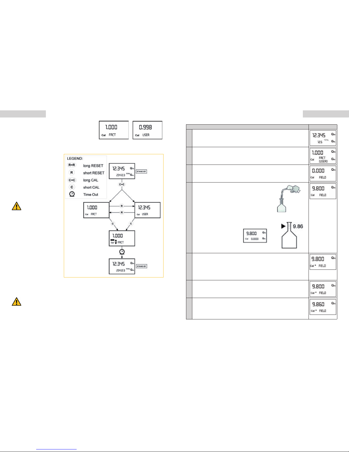
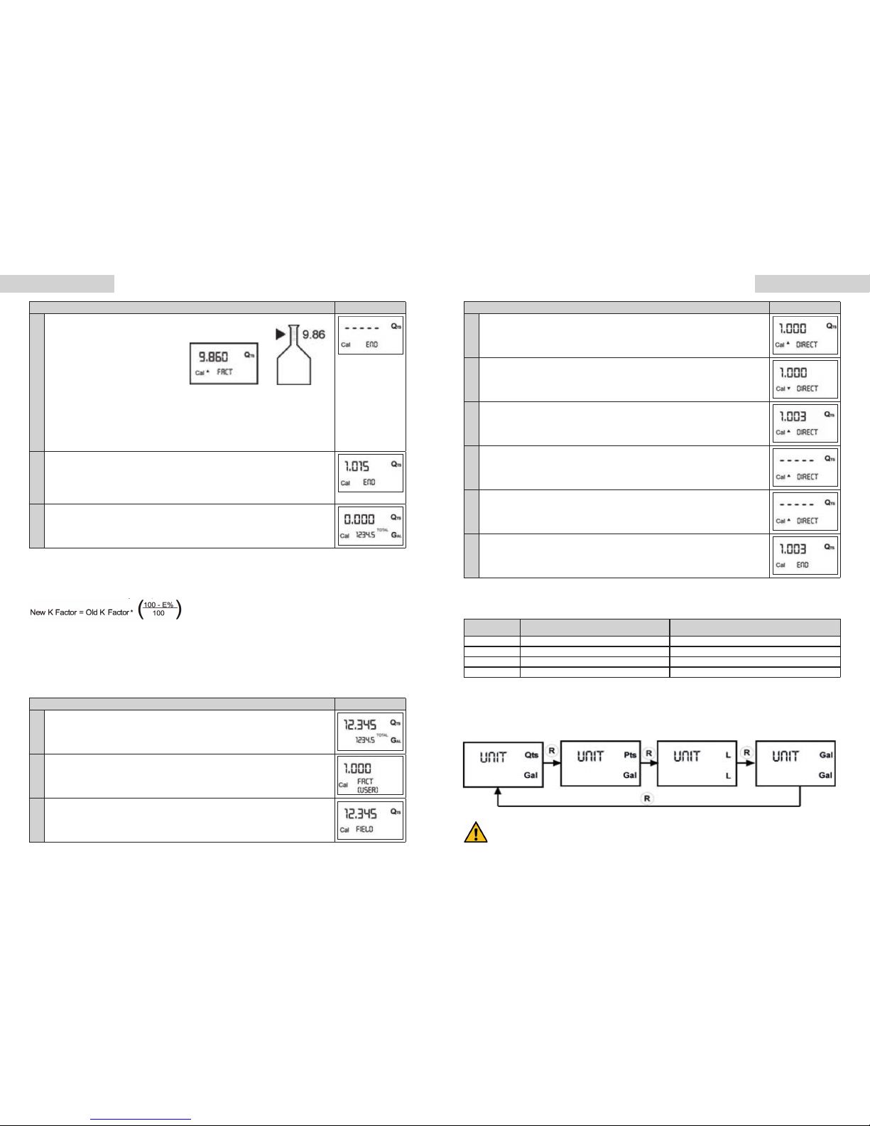
10. Callibration .......................................................................................................................................................... 5
11. Meters conguration ............................................................................................................................................ 9
12. Maintenance ...................................................................................................................................................... 10
13. Recognising and repairing of mistakes ............................................................................................................. 10
14. Guarantee regulations ....................................................................................................................................... 11
15. Notes on Product Liability ................................................................................................................................. 11
16. Notes on Disposal ............................................................................................................................................. 11
17. EU Declaration of Conformity ............................................................................................................................ 11
12. Technical Data ................................................................................................................................................... 12
English 32 English
1. INTRODUCTION
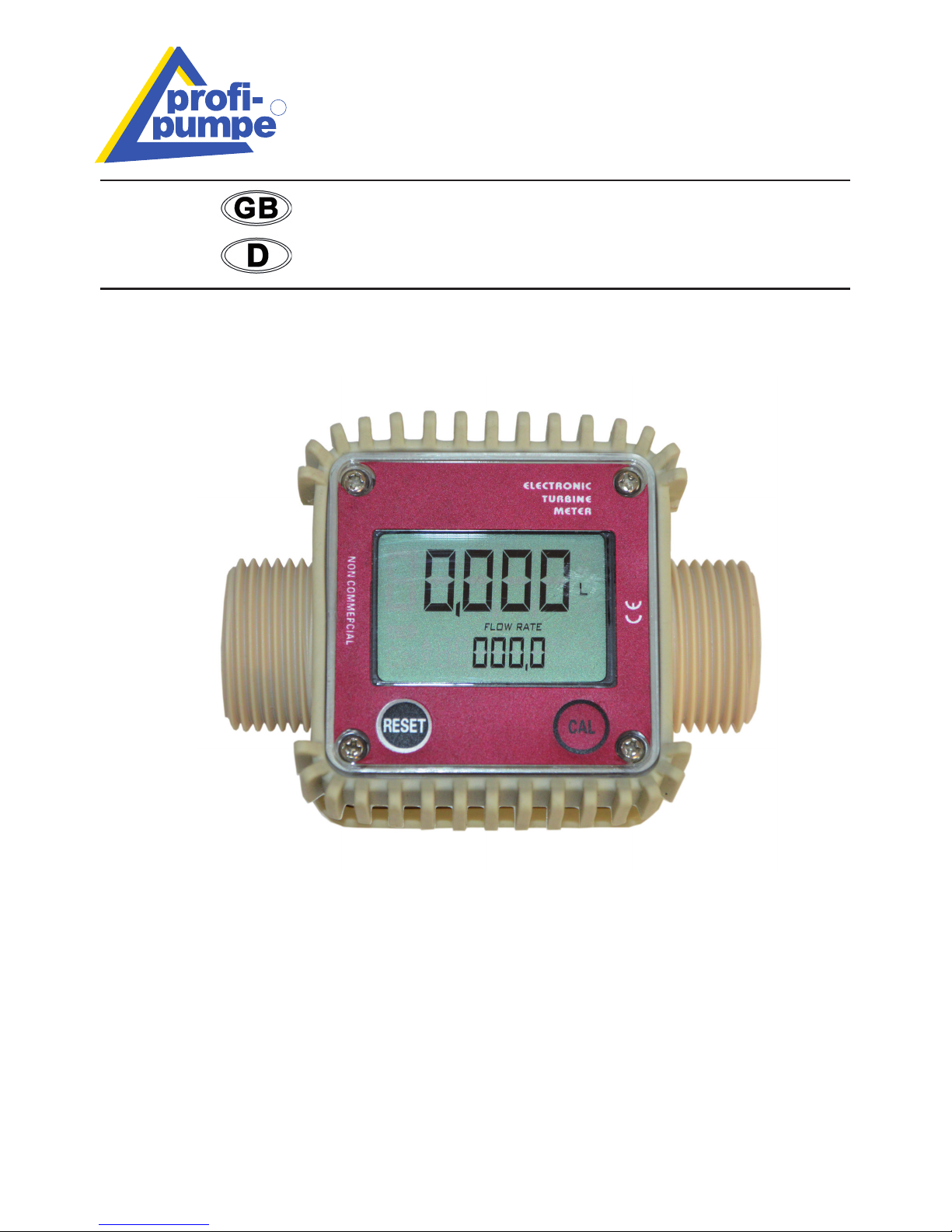
We would like to congratulate you on the purchase of our K24 Electronic digital meter. We appreciate your trust. That‘s
why funtional security and operational safety stands by us on rst place.
To prevent damage to persons or property, you should read this user manual carefully. Please
observe all safety precautions and instructions for proper use of the K24 meter. Failure to follow
the instructions and safety precautions can result in injury or property damage.
Please keep this manual with the instructions and safety instructions carefully in order to at any
time you can restore them.
2. IN GENERAL
K24 Electronic digital meter featuring a turbine measurement system, designed for precise measuring of low viscosity uids.
It is divided into two using macrogroups:
l With body made of inconductive plastic material of light colour, designed to be used with water / urea solution
l With body made of conductive plastic material of dark colour (assessed resistance: 50 ohm), designed to be used
with DIESEL FUEL, WATER and windscreen uids. The card can be rotated with respect to its housing, thus allow-
ing easy display readings in any position. The card housing, easily accessible, is closed by a plastic cover sealed
through a rubber protection acting as a gasket as well. The whole unit can be easily removed by unscrewing the 4
screws xing thecard and the cover.
Turbine measurement system. The turbine is placed inside a hole through the body of K24, tted with threaded inlet
and outlet. The body of K24 is made of a plastic material that allows several types of threads with relevant combina-
tions. K24 has 2 rubber protections, designed to act as gaskets, too, and thus reducing the number of its components.
The liquids compatible with K24 must be at low viscosity, namely: Diesel fuel, Water, Water/urea solution, Kerosene,
Windscreen - Petrol
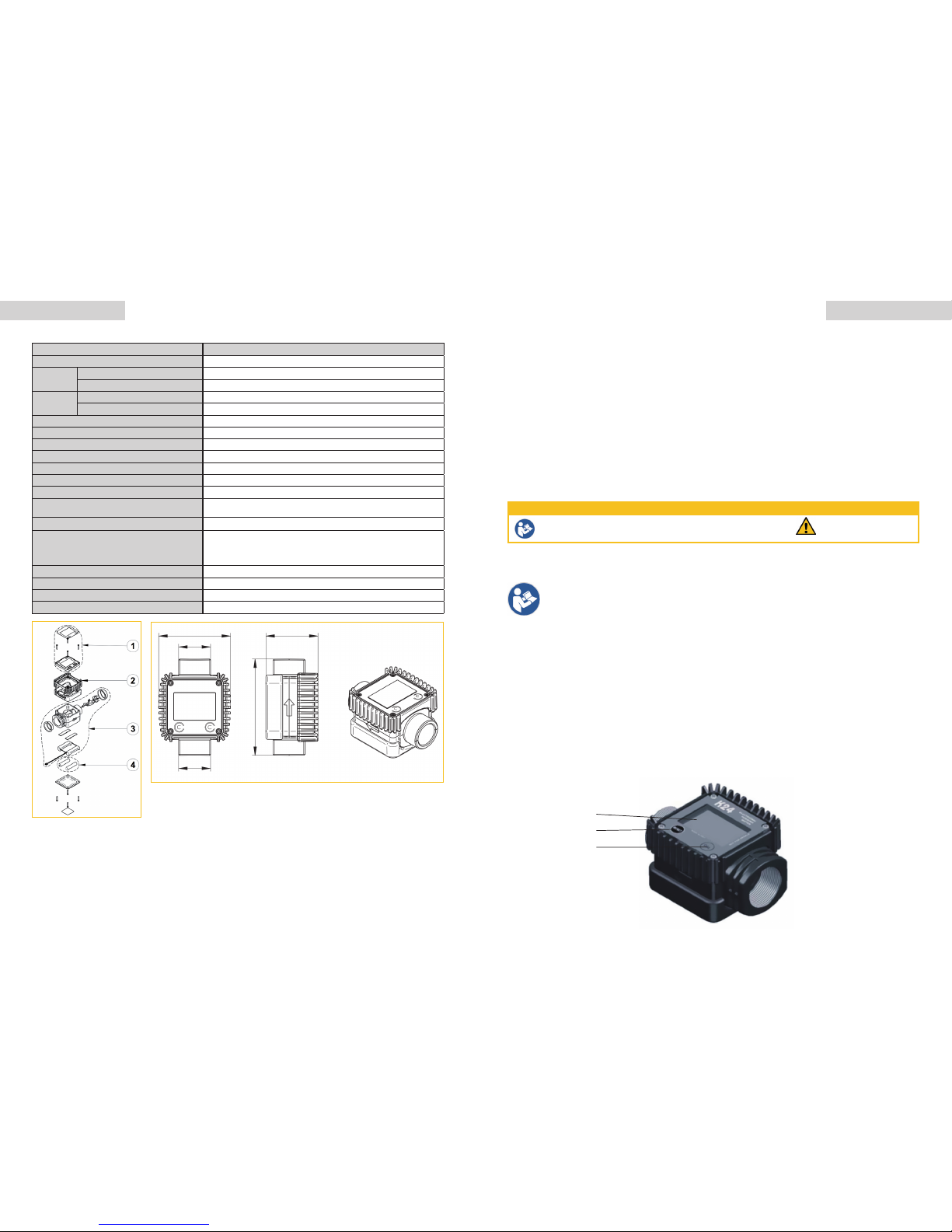
3. MAIN COMPONENTS
Please read the user manual before using the K24 Electronic digital meter Warning sign
SAFETY INSTRUCTION AND WARNINGS
WhilexingtheK24
card, make sure the bat-
tery contact cable is not
placed above the circular
housing of the bulb.
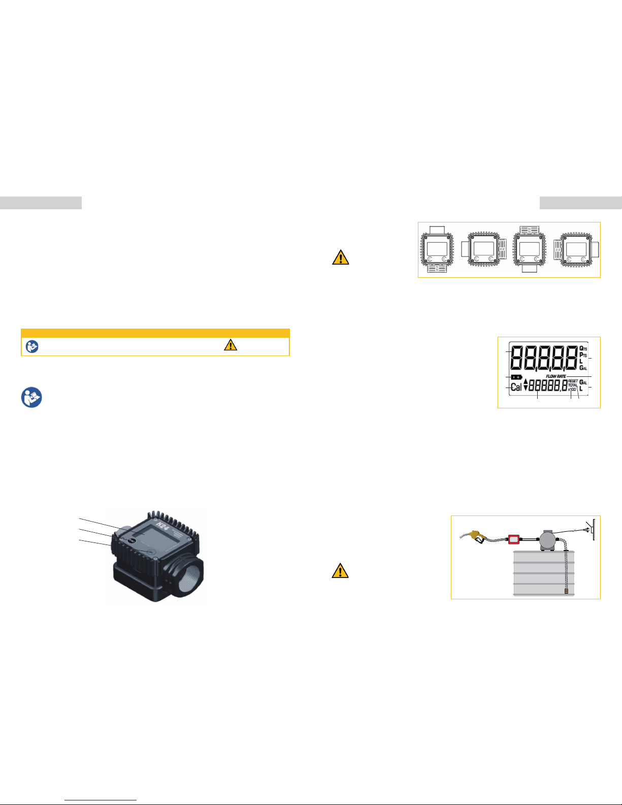
3.1. DISPLAY POSITIONING
The square shape of the k24 body
allows the card to be rotated in
its housing, thus ensuring great
versatility in positioning.
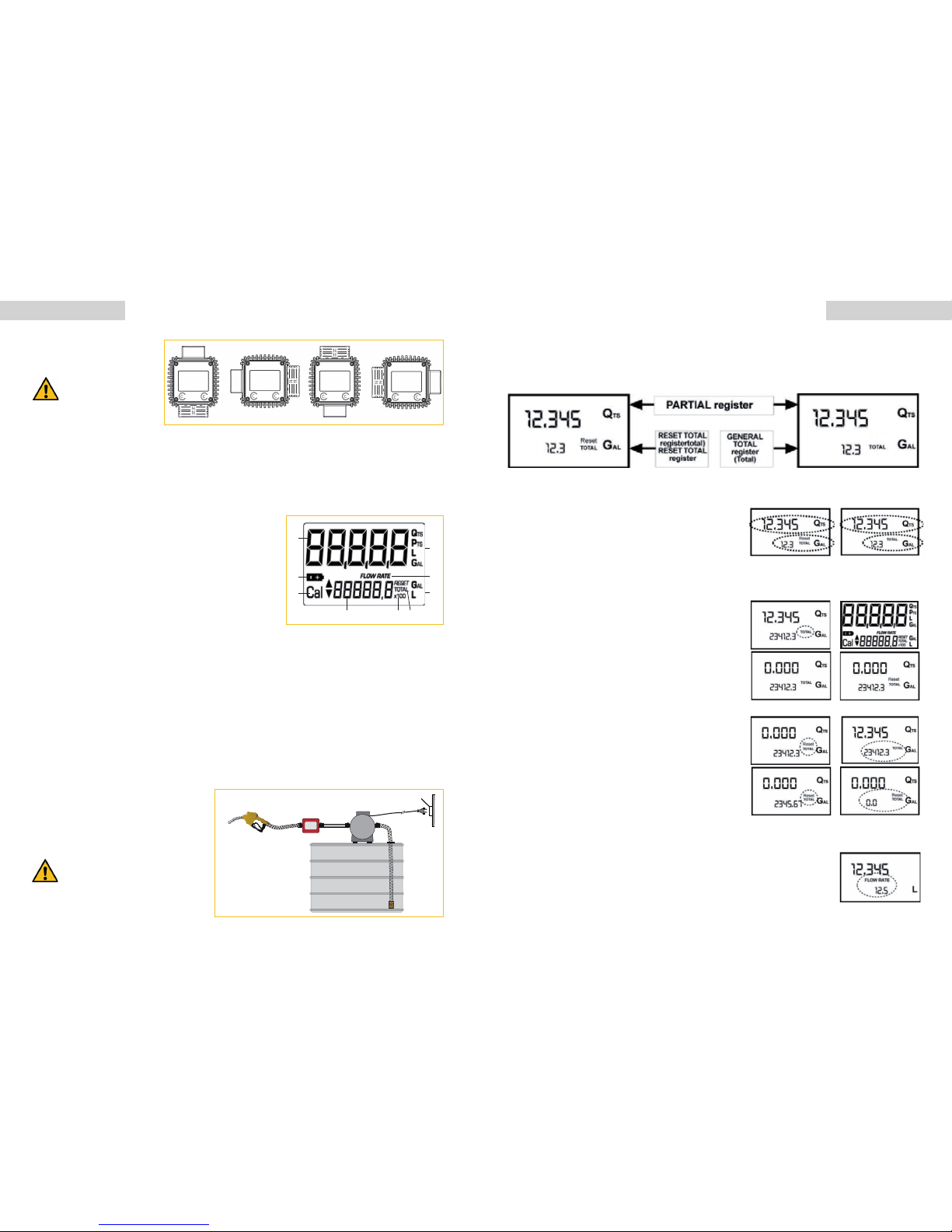
4. OPERATING MODES
The user can choose between two different operating modes:
l
Normal Mode: Mode with display of Partial and Total dispensed quantities.
l
Flow Rate Mode: Mode with display of Flow Rate, as well as Partial dispensed quantity.
The meter features a non-volatile memory for storing the dispensing data, even in the event of a complete power break
for long periods. The measurement electronics and the LCD display are tted in the top part of the K24 which remains
isolated from the uid-bath measurement chamber and sealed from the outside by means of a cover.
6. USER BUTTONS
The k24 features two buttons (reset and cal) which individually perform two main functions and, together, other
secondary functions. The main functions performed are:
lFor the reset key, resetting the partial register and resettable total (reset total)
lFor the cal key, entering instrument calibration mode.
Used together, the two keys permit entering conguration mode, useful for changing the units of measurements and
calibration factor.
7. BATTERY HOUSING
The k24 is powered by two standard type 1.5 V batteries (size AAA). The battery housing, easily accessible, is closed
by a metal cover sealed through a rubber protection acting as a gasket as well. The whole unit can be easily removed
by unscrewing the 4 screwsxingthe cover and the protection to the body.
8. INSTALLATION
Theinstallationmustbeperformedbyaqualied
professional.
K24 features a threaded, perpendicular inlet and
outlet (1 and female that can be combined together).
It has been designed to be easily installed in any
position: xed in-line or mobile on a dispensing
nozzle. In order to improve the life of the turbine, it is
recommended to t a strainer before the meter itself.
At the female inlets, tighten the coup-
lingsatamax.torqueof55N/m.
ITH THE GAS-FEMALE INLETS, DO
NOT USE CONICAL THREADED COU-
PLINGS.
RESET button
LCD Display
CAL button
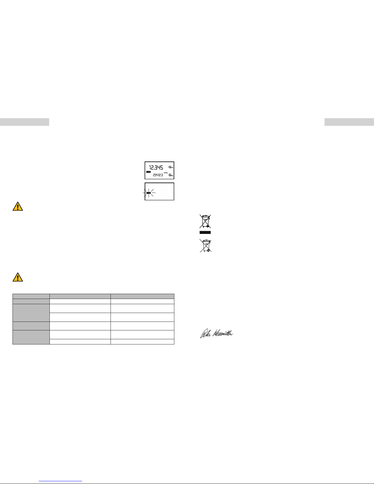
5.LCDDISPLAY
The „LCD“ of the METER features two numerical registers and various indi-
cations displayed to the user only when the applicable function so requires.
Key:
1. Partial register (5 gures with moving comma FROM 0.1 to 99999) in-
dicating the volume dispensed since the reset button was last pressed
2. Indication of battery charge
3. Indication of calibration mode
4. Totals register (6 gures with moving comma FROM 0.1 to 999999),
that can indicate two types of Total:
4.1. General Total that cannot be reset (TOTAL)
4.2. Resettable total (Reset TOTAL)
5. Indication of total multiplication factor (x10 / x100 )
6. Indication of type of total, (TOTAL / Reset TOTAL)
7. Indication of unit of measurement of Totals: L=Litres Gal=Gallons
8. Indication of Flow Rate mode
9. Indication of unit of measurement of Partial: Qts=Quarts, Pts=Pints, L=Litres, Gal=Gallons
1
2
3
4 5 6
7
8
9
88,8,8,8
888888,8,8,8
*AdBlue, a registered trademark of Verband der Automobilindustrie e. V. *AdBlue, a registered trademark of Verband der Automobilindustrie e. V.