Profile CD7400 Service manual

AM/FM HIGH POWER FLIP DOWN DETACHABLE FACE
CD PLAYER
CD7400
INSTALLATION INSTRUCTIONS / OWNER S MANUAL
,

1
INTRODUCTION
Congratulations on your purchase of a Profile state-of-the-art single disc CD
player. Your selection of a Profile car audio product indicates a true appreciation
of fine musical reproduction. Whether adding to an existing system or including
your Profile CD player in a new system, you are certain to notice immediate
performance benefits.
FEATURES
50W x 4 Power Output Power Level Meter
Dual RCA Line Output(Front & Rear) ISO/DIN Mounting
Clock Blinking Security L.E.D.
30 Station Memory Full Electronic Function Controls
4 Band Preset Equalizer Disc Scan, Random & Repeat Play
KEEP YOUR SALES RECEIPT
Take this time to attach your sales receipt to the manual and put in a safe place.
In case of any reason this product may need warranty service, your receipt will
be necessary to establish purchase date.
IMPORTANT! Before making any connections, disconnect the car s battery
until the installation is completed to avoid possible damage to the electrical
system.
Serial # Purchase Date
,

2CD7400
SAFETY PRECAUTIONS
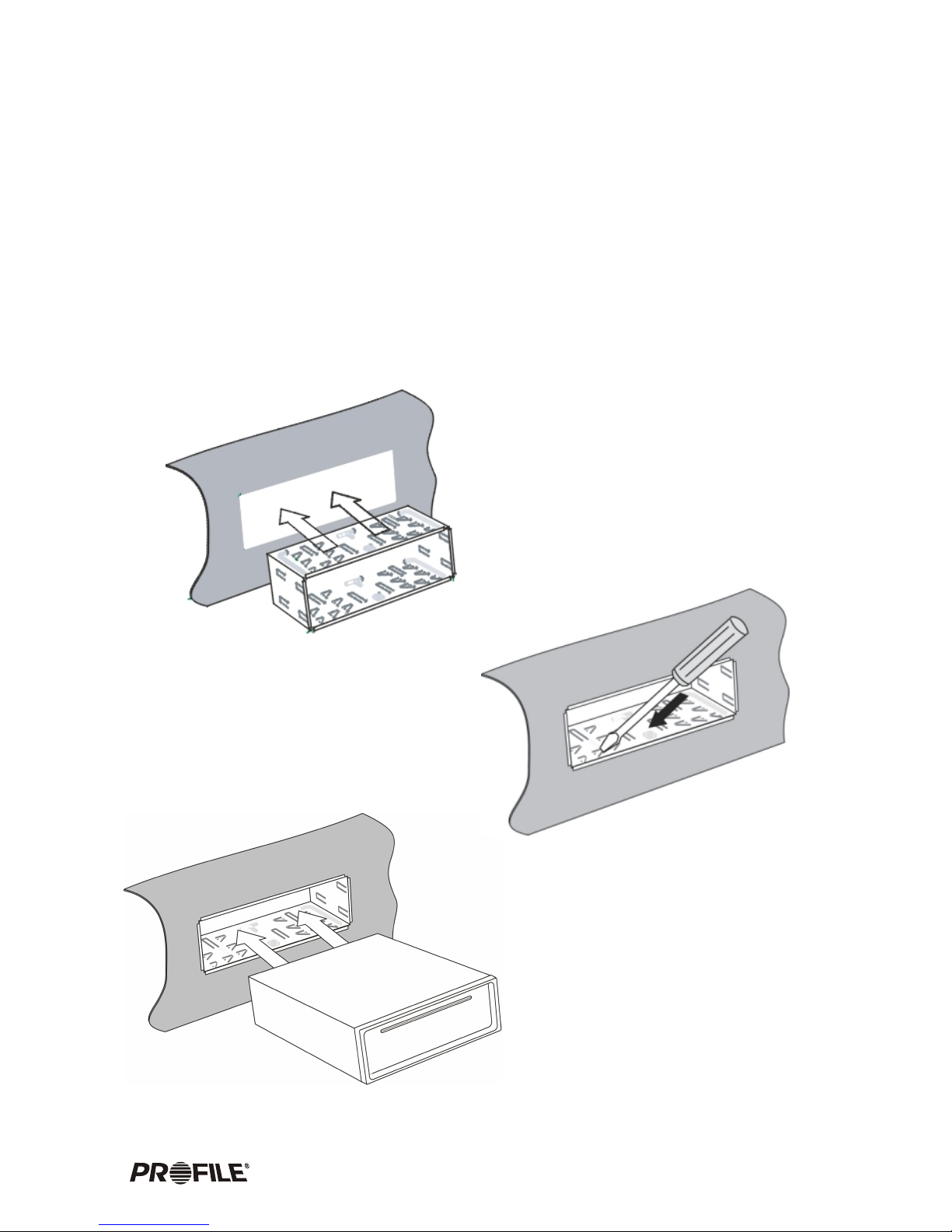
Secure the CD player
When installing your CD player in the vehicle, make sure it is mounted properly in the dash,
using an after market installation kit if needed. When using the supplied mounting sleeve,
it is a must that you also use the supplied back brace to support the back of the CD
player.
Use caution when mounting the CD player.
Remember there are many electrical wires, vacuum lines, brake lines and air bag deployment
wires. Make sure you know where they are when mounting the CD player to avoid puncturing
lines, and shorting wires.
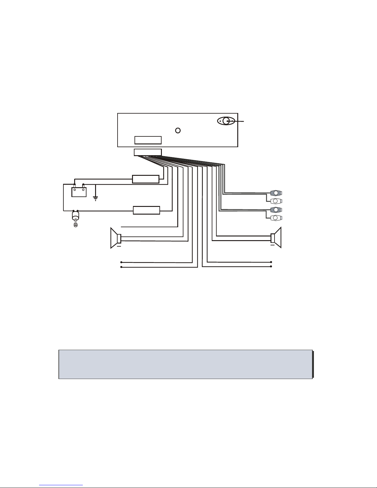
Use high grade wire connectors.
To ensure maximum power transfer and secure safe connections, it is recommended to use
high grade barrel or crimp cap connectors.
Do not run any wires underneath the vehicle.
Exposed wires can be cut or damaged. It is best to run all wires through the vehicle under the
carpet and/or side panels. This enables to a cleaner installation and less risk of damage.
Run signal wires away from electrical wires
To avoid possibility of induced noise from the car's electrical system (i.e. popping noises or
engine noise), run signal wires away from the car's electrical wiring.
Make all ground wires as short as possible and terminated at the same point.
In order to reduce the chance of ground loops (i.e. engine noise), make the grounded wire as
short as possible to reduce the wire's resistance. Also, when using multiple components, make
sure all units are grounded at the same point.
Avoid sharp edges when running the wires.
To avoid the possibility of power, signal or speaker shorts, be careful not to allow the amplifier
wires to come in contact with sharp edges. Use a grommet to protect the wire when running
through the fire wall .
.
.

3
CARE AND MAINTENANCE
Cleaning the CD player
When cleaning the vehicle, be sure not to get any water in or on the CD player. Clean only the
exterior surface of the unit with a dry, clean soft towel using no chemical solvents.
Operating in extreme temperatures
Sometimes the unit will not operate in extreme, hot or cold temperatures. If this is the case,
wait until the temperature in the vehicle is normal, then resume operation.
Protect your CDs.
When not using the disc player, it is recommended that you remove the CD.
Do not leave an
ejected disc sitting on the edge of the disc player for long periods of time.
The disc will warp
under direct sunlight. Always put each disc in its case to protect them during times of non-use.
CD operation.
Never attempt to force anything other than a compact disc in the disc slot. This disc player is
a precision instrument that could be damaged by a foreign object.
Disc skip
When driving down a very rough road, the disc may skip. This will not scratch or damage the disc.
Removing and protecting detachable front panel.
The front panel of the radio may be removed as a theft deterrent. After removing the front
panel, use the case provided to keep the front panel from getting damaged.
.
.
Press the OPEN button to flip down the front panel (fig.1), then pull out the
front panel (fig.2) and put it in the protective case (fig.3) for safe keeping.

4CD7400
DISC CARE AND PLAY:
Before playing, clean the disc with a clean, lint-free cloth.
Wipe the disc in the direction of the arrow.
Do not use solvents such as benzine or thinners. Commercially available
cleaners or anti static spray will damage the unit.
Insert a disc with the labeled surface up.
Do not try to insert another disc when one has already been inserted.
Doing so may damage the unit.
Label
surface up
Handle the disc by its edge to keep the disc clean and do not touch
the surface.
Do not stick paper or tape on the disc.
Do not expose the disc to direct sunlight which can cause the disc to warp.
Always store the disc in its case for protection. Scratched up discs will
produce poor sound performance and cause CD player to skip.

5
++
++++
++
YELLOW
ANTENNA CONNECTOR
MEMORY +12V
BLACK(GND)
RED (B+)
FRONT RIGHT
SPEAKER
BLUE AUTO ANT
WHITE
WHITE/BLACK
GREEN/BLACK VIOLET/BLACK
GRAY/BLACK
GRAY
VIOLET
GREEN
FUSE
FUSE
15 A
0.5 A
ELECTRICAL AND SIGNAL CONNECTIONS
FOUR SPEAKER SYSTEM
BATTERY
+12V
+-
SWITCHED +12V
(ON WITH IGNITION)
Before making the following connections, take time to look over the vehicle s wiring and
determine the location and wires you will be connecting to. If you do not wish to cut or tap into
the vehicles existing factory wiring, there are wiring kits available at your car audio retailer
that will allow you to plug directly into the factory wiring harness. Make sure to test all wires
before connecting to the CD Player.
,
!Connect Black wire to chassis ground.
!Connect the Yellow memory backup wire to a Constant +12 Volt power source wire.
!Connect the Red ignition wire to a switched +12 Volt power source wire. (The power
wire that is energized when the key is in the accessory position).
!The blue wire is connected only if a power antenna or an amplifier is used in the
system. This wire supplies +12 Volt output when the CD Player is turned on,
which activates most power antenna relays or amplifier turn on circuits.
Low level signal output for
connection to amplifier or
signal processors.
R
L
R
L
R CH RED
L CH WHITE
R CH RED
L CH WHITE
BLACK
GRAY
FRONT RCA OUTPUT
REAR RCA OUTPUT
REAR RIGHT
SPEAKER
FRONT LEFT
SPEAKER
REAR LEFT
SPEAKER

6
NOT USED
NOT USED
NOT USED
NOT USED
CAUTION! Tape unused wires so they do not short against other wires or
chassis ground.
++++
YELLOW
ANTENNA CONNECTOR
MEMORY +12V
BLACK(GND)
RED (B+)
FRONT RIGHT
SPEAKER
BLUE AUTO ANT
WHITE
WHITE/BLACK GRAY/BLACK
GRAY
FUSE
FUSE
15 A
0.5 A
TWO SPEAKER SYSTEM
BATTERY
+12V
+-
SWITCHED +12V
(ON WITH IGNITION)
Low level signal output for
connection to amplifier or
signal processors.
R
L
R
L
R CH RED
L CH WHITE
R CH RED
L CH WHITE
BLACK
GRAY
FRONT RCA OUTPUT
REAR RCA OUTPUT
FRONT LEFT
SPEAKER
CD7400

7
MOUNTING THE CD PLAYER
There are two different ways to mount the CD Player. In most Japanese vehicles you can use
the factory mounting brackets, taking advantage of the ISO/DIN opening. If your vehicle
does not have ISO/DIN opening, you can mount the CD Player using the supplied DIN sleeve
and rear support bracket. When considering your mounting location, make sure the unit will be
leveled. If you cannot mount the CD Player level, due to your vehicles design, make sure there is
no more than a 30 degree tilt. Keeping this in mind will assure proper CD play and overall reliability.
DIN SLEEVE MOUNTING
Insert the mounting sleeve into a
standard DIN cutout in the dash
kit, dashboard or Console.
Bend the mounting tabs of the sleeve
with a screwdriver to secure the bracket
firmly in place.
Insert the CD Player in the
mounting sleeve until it locks.

8
Attach the back brace to the CD
player using the supplied hardware.
Then attach the other end of the
brace to a firm mounting surface
(i.e. Dash brace, fire wall, e.t.c.)
This will brace the back of the CD
player to ensure solid mounting to
prevent theft and provide optimal
CD play.
Once the CD player is secured, fit the trim ring over outside edge of the radio until it snaps
into place. Insert the face plate with the left side first. Angle in the left side slightly then
gently push the right side of face plate until it snaps completely in place.
CD7400

9
ISO/DIN MOUNTING
If you own a Japanese vehicle, you can use the standard ISO/DIN mounting screw holes on
the side of the CD player to attach to the existing factory mounting bracket, without using
the provided DIN sleeve.
Remove the factory ISO/DIN mounting bracket from the car along with the factory radio.
Remove the factory radio from the bracket by unscrewing the two Phillips screws on each
side of the radio paying close attention to their screw positions and saving the screws to
mount the CD player.
Remove the two spring clips from each side of the CD player by removing the screws. These
clips are not used in ISO/DIN mounting method and must be removed to expose the ISO/
DIN mounting holes.
Also remove the detachable face and rectangular trim ring from the CD player and mount the
CD player to the factory ISO/DIN bracket using the screws that you removed from the
factory radio.
Connect the wire harness and antenna plug to the back of the CD player. Then mount the
factory ISO-DIN bracket to the car.
Note: It is not necessary to attach the outer rectangular trim ring for ISO/DIN mounting method.
REMOVING THE CD PLAYER
To remove the CD player from an ISO/DIN mount, follow the above mounting procedure in
reverse order.
To remove the CD player from a sleeve mount, use the pair of keys provided.
Remove the rectangular trim ring by
applying pressure with your finger
tips, then gently pull out away from
the dash.
Insert the provided removal key into the opening on each side of the CD player.
Push the keys inward until they snap in place. Firmly grab the keys and slowly
pull the CD player out away from the dash.
PLACE FINGER TIPS HERE
!
!
!
!
!
!
!

10
LOCATION AND FUNCTION OF CONTROLS
CD7400

11
1
2 FLIP DOWN PANEL
Press the OPENbutton to flipdown the frontpanel. This willallow you toinsert
or eject aCD and alsoremove the frontpanel.
3 CD PLAY
To play aCD, press theOPEN button toflip down thefront panel exposingthe CD
inserting slot. Gentlyinsert the CDinto the slotwith the labelside facing up.The
disc will automaticallybe loaded intothe unit andstart playing thefirst track of
the disc. Thedigital display willindicate the tracknumber.
4 EJECT CD
To remove aCD once inserted,press the OPENbutton to flipdown the frontpanel
and press theEJ button locatedon the rearface of thepanel. Once theCD is
ejected, the unitswitches to radiomode.
5 VOLUME UP
Press the +button to increasethe system svolume.
6 VOLUME DOWN
Press the -button to decreasethe system svolume.
7 MODE
Press the MODEbutton to changebetween tuner (radio)and CDP (CDplaying)
mode.
8 BAND
Under radio modepress the BNDbutton to changebetween three FMbands and
two AM bands.
FM 1 FM 2 F M 3 AM 1 AM 2
POWER
To turn ON the unit, pressany button exceptthe EJECT andOPEN button.
To turn OFF the unit, pressthe PWR button.
,
,
“

12
9 10 RADIO TUNE & CD TRACK UP/DOWN, CD FAST FORWARD/REWIND
Under radio mode,press the 9 or 10 buttonmomentarily and repeatedlyto
change the frequencynumber up ordown one step.Press and holdthe button for
more than 1second to seek to the nextclear station.
In CD playmode, press the 9 or 10button to moveto the next or previous track.
In CD playmode, press and hold the 9 or 10 buttonto fast forwardor fast
reverse through thesong. The CD resumes playing whenthe button isreleased.
11 PRESET STATIONS
There are 6numbered buttons to store into memory and recall stations for each
band. Select aband (if needed)as explained in 8 . Tuneto a radio station that
you wish tostore. Select, press, and hold a preset numbered button for 2 seconds
until you heara beep indicating that the station has been stored in memory. To
recall a presetstation, simply push the numbered preset button.
12 FUNCTION SELECT
SEL button allowsyou to displaydifferent functions foradjustments. Press the
SEL button momentarilyand repeatedly tomove the displayfrom Volume, Bass,
Treble, Balance, andFader functions. Use+ 5 and - 6 buttonsto adjust the
selected mode. Whenthe mode hasnot been adjusted for several seconds, display
and mode returnsto normal radioor CD operation.
VOL BAS TRE BAL FAD
(Volume) (Bass) (Treble) (Balance) (Fader)
VOLUME - Pressthe SEL buttononce. Adjust the volume level using the + 5 and
- 6 buttons.
BASS - Pressthe SEL buttontwice. Adjust the bass level using the + 5 and - 6
buttons.
TREBLE - Pressthe SEL button three times. Adjust the treble level using the +
5 and - 6 buttons.
BALANCE - Pressthe SEL button four times. Adjust the sound balance between
left and rightspeakers using the+ 5 and- 6 buttons.
FADER - Pressthe SEL button five times. Adjust the sound balance between front
and rear speakersusing the + 5 and - 6 buttons.
CD7400

13
DSP - Theunit is equipped with 4 presetequalization modes. Pressthe SEL button
for more than1 second todisplay DSP OFF. Then use + 5 and - 6 buttons
to choose oneof 4 followingpreset EQ s in the followingorder. In DSPOFF
mode, the EQis controlled byBass and Treblesettings.
DSP OFF FLAT CLASSIC ROCK POP
BEEP - Thebeep sound when you press abutton on theunit can beturned on or
off. Press theSEL button for more than 1second to displaythe DSP
function. Press theSEL button again momentarily to displayBEEP ON/OFF.
Then use + 5 and - 6 buttons toturn on/off the beep sound.
SET VOL -A certain Volume Level can beset to comeon when theunit is turned
on or canbe set to come on atthe same lastlevel before theunit was
turned off. Pressthe SEL button for more than1 second todisplay
the DSP function.Press the SEL button twice momentarilyto display
VOL LAST/ADJ. Use+ 5 and- 6 buttonto choose between VOL
LAST and VOLADJ. To set the volume toa certain level,press the
SEL button momentarilywhen VOL ADJ is displayed. Thenuse + 5
and - 6 buttons to adjustto certain volumelevel when A-VOL is
displayed.
13 CD TOP/PAUSE
In CD playmode, press the TOP 13 buttonto pause CDplay. Press again to
resume normal play.
In CD playmode, press the TOP 13 buttonfor more than1 second to go back
to the topof the disc and play the first track.
14 CD SCAN
In CD playmode, press the INT 14 buttonto turn onintro playing first10
seconds of eachtrack. When wish to listen tothe whole trackduring intro mode,
press the buttonagain to turn off intro.
15 REPEAT PLAY
In CD playmode, press the RPT 15 button to continuously playing the current
track. Press itagain to cancelthe repeat feature.
Press the SELbutton for morethan 1 secondto display additionalset of functions
for adjustments, suchas DSP, BeepOn/Off, and VolumeLast/Adjust.
,

14
16 RANDOM PLAY
In CD playmode, press the RDM 16 buttonto play alltracks of thedisc in random
sequence. Press itagain to cancel random play.
17 RADIO SCAN
In radio mode,press the SCN 17 button to scan up onestrong radio stationsignal
at a time.If a valid radio station is detected, the station number will blink on the
LCD for 3seconds before moving onto the next strong station. Pressing the
button again willstop the scanprocess and remain on current radio station.
18 AUTOMATIC STORING & PRESET SCANNING
In radio mode,press and holdthe A.P. 18 button for morethan 2 secondsto
activate the automaticstoring function. Onceactivated, the radiostarts search-
ing for first6 strong signaledstations and storesthem into thepreset memory.
After completion, theradio will tuneback to thefirst preset memorystation.
In radio mode,press the A.P. 18 button formomentarily to activatethe preset
scanning function. Onceactivated, the radiostarts scanning all preset memory
stations for fewseconds at atime while thepreset memory numberflashes on
the LCD. Pressingthe button againwill stop thescan.
19 MUTE
Press the MUTEbutton to silence the system. Pressa second timeto resume
listening.
20 MONO/STEREO
Monaural (Mono) orStereo mode can be selected forFM tuner sreception. For
best quality sound,stereo mode should be selected. However, Mono mode canbe
selected to helpthe reception of distant radio stations. Press the STbutton to
select between Monoand Stereo modes.
21 CLOCK
Press the CLKbutton to display the time on the LCD for 5 seconds. Toadjust the
time, press andhold the CLK button until the time flashes and use the + 5 button
to adjust thehours and - 6 button to adjust the minutes.
22 RESET
The reset buttonshould be pressed when installation iscomplete and alsowhen
all buttons donot operate.
23 SECURITY LED
Designed as atheft deterrent, the red LED willflash when theunit is turnedoff
and front panelremoved.
,
CD7400

15
TROUBLE SHOOTING THE SYSTEM
The following chart will help in solving most problems that may occur. Should any problem
persist after you have made these checks, please consult your nearest Profile retailer.
Before going through this check list, refer back to the wiring and operating procedures.
SYMPTOM CAUSE SOLUTION
The vehicle's ignition switch
is not on.
Turn the ignition switch to the accessory
position. If there is still no power, check the
fuses at the vehicle's fuse block or the
radio's fuse leads.
The fuse is blown. Replace the fuse with another fuse of the
same recommended value
There is a disc already in
the player.
Remove the disc in the player, then put in
the new one.
You are trying to put the
compact disc in upside down.
Insert the compact disc with the label facing
up.
The compact disc is
extremely dirty or
defective.
Clean the compact disc with a compact disc
cleaning solution or replace the defective
compact disc.
The temperature in the car
is too hot.
Cool the inside of the vehicle, then try again.
Condensation build-up on the
inside of the unit.
Leave the disc player off and turn the
vehicle's air conditioner on to remove the
condensation build-up inside the unit.
The volume control is all the
way down.
Adjust the volume control.
The speakers are bad. Test the speakers to determine if they need
replacing.
The function
buttons do
not work.
The built-in microprocessor
is operating incorrectly.
Remove the disc, then re-insert it. Press the
reset button .
No Power
Disc cannot
be loaded or
ejected.
No sound.
New installation. Press the RESET button.
22
E 1~ E 10 The unit cannot be operated because of trouble. Press the "RESET"
button . If theindicator still appears after pressing the"RESET"
button , your unit needs repair. Please refer to the warranty section
of this manual for details on getting the unit serviced.
.
ERROR CODES
22
22
22

SYMPTOM CAUSE SOLUTION
The installation angle is
greater than 30 degrees
Adjust the angle of the unit to less than 30
degrees
The disc player is installed
incorrectly
Check to see if the unit is fastened securely
with the back brace supporting the rear of
the unit.
The compact disc is
extremely dirty or defective
disc.
Clean the compact disc with a compact disc
cleaning solution or replace the defective
compact disc.
Condensation build-up on the
inside of the unit.
Leave the disc player off and turn the
vehicle's air conditioner on to remove the
condensation build-up inside the unit.
The antenna is not
connected or the antenna is
bad.
Check the antenna and connection to insure
proper performance.
The signals in your listening
area are weak.
Select stations manually and make sure the
tuner is in the distant stereo mode.
The radio
does not
work. The
Radio station
automatic
selection
does not
work.
The compact
disc skips.
16 CD7400

SPECIFICATIONS
GENERAL
Power Supply Requirements...........................................DC 12 Volts, Negative Ground
Chassis Dimensions (mm)......................................................178(W) x 165 (D) x 50 (H)
Tone Controls...........................................................................................................................
Bass @ 100Hz..........................................................................................+10dB / -10 dB
Treble @ 10Khz.......................................................................................+10dB / -10 dB
Equalizer..................................................................................................................4 Presets
Maximum Output Power.........................................................................................50W x 4
RMS Output Power..................................................................................................30W x 4
Maximum Current Consumption........................................................................15 Ampere
Fuses
Memory (Constant)........................................................................................15 Ampere
Accessory (Switched).................................................................................0.5 Ampere
RCA line out voltage.....................................................................................................3.7 V
CD PLAYER
Signal to Noise Ratio...................................................................................................>85dB
Channel Separation......................................................................................................>80dB
Frequency Response........................................................................................5Hz ~ 20Khz
Usable Disc....................................................................................CD/CD-R/CD-RW Discs
RADIO
FM
Frequency Coverage..............................................................................87.5 to 107.9MHz
IF................................................................................................................................10.7MHz
Station Presets...................................................................................................................18
AM
Frequency Coverage.................................................................................530 to 1710KHz
IF.................................................................................................................................450KHz
Station Presets...................................................................................................................12
Due to continuing product improvement, specifications subject to change without notice.
17

LIMITED WARRANTY
Profile Consumer Electronics, Inc. warrants this product to be free from defects in
material and workmanship for a period of One (1) Year from the date of sale to the
original consumer purchaser. If this product is proven to be defective within this one
year period, Profile will repair it when said product is returned, with a copy of the
dated sales receipt, freight prepaid to Profile.
This warranty is valid only in the United States. This warranty does not cover any
expense incurred in the removal and/or re-installation of this product. This warranty
does not cover any Profile product damaged by accident, misuse, abuse, improper line
voltage, fire, water, lightning, or other acts of God. This warranty is void if any parts
and/or service is/are furnished by anyone other than Profile. This warranty is void if
the factory applied serial number is altered or removed from the product.
This warranty does not cover cartons, cases, batteries, broken or marred cabinets,
magnetic tapes, or any other accessories used in connection with this product or
consequential damages due to a defect in the product.
Any implied warranties, including fitness for use and merchantability, are limited in
duration to the period of the express warranty set forth above. No person is
authorized to assume for Profile any other liability in connection with the sale of the
product. Profile expressly disclaims liability for incidental and consequential
damages that might be caused by this product. The remedies provided under this
warranty are exclusive and lieu of all others.
This warranty gives you specific legal rights. You may have other rights which vary
from state to state or province to province. Some states or provinces do not allow
limitation on how long warranties last, so the above may not apply to you. Additionally,
some states/provinces do not allow the exclusion to limitation of consequential or
incidental damages, so the above limitation or exclusion may not apply to you.
* In the space below, record the serial number that is located on the back of the unit
along with the purchase date and location.
Model Number __________________ Serial Number
____________________
Purchase Date __________________ Where Purchased _________________
RETAIN YOUR SALES RECEIPT ALONG WITH THIS CARD. IT IS YOUR ONLY
VALID DOCUMENT TO RECEIVE WARRANTY SERVICE.

PROFILE CONSUMER ELECTRONICS, INC.
15060 SHOEMAKER AVE
SANTA FE SPRINGS, CA 90670
TEL: (562)404-9393 FAX: (562)404-9433
WWW.PROFILEUSA.COM
WARRANTY REPAIR POLICY
In the unlikely event of product failure, the following procedures
should be followed
1) The unit must be under the 1-year warranty period.
2) The unit must have no physical damage.
3) A copy of the original proof of purchase must be sent with the unit.
4) Include a brief description of the problem or failure with the unit.
5) Include the return street address and daytime telephone number.
6) Allow 2~3 weeks for repair (this period includes shipping time).
Send unit to: PROFILE CONSUMER ELECTRONICS, INC.
15060 SHOEMAKER AVE
SANTAFE SPRINGS, CA90670
TEL: (562)404-9393
Note:All units failing to meet the above requirements will be
subject to a charge and or may not be repaired.
Table of contents
Other Profile Car Receiver manuals

Profile
Profile CD7200 Service manual

Profile
Profile CD6500 Service manual

Profile
Profile MP9900 Quick start guide

Profile
Profile PCD970R Service manual

Profile
Profile CD8700 Service manual

Profile
Profile CD8200 Service manual

Profile
Profile PCD950R Service manual

Profile
Profile PCD920 Service manual

Profile
Profile MP9700 Service manual