REHATEAM s.r.l.—vicolo Negrelli 5—31038 Castagnole di Paese TV—www.rehateamprogeo.com Service Manual MOTOTRONIK 2
SERVICE MANUAL
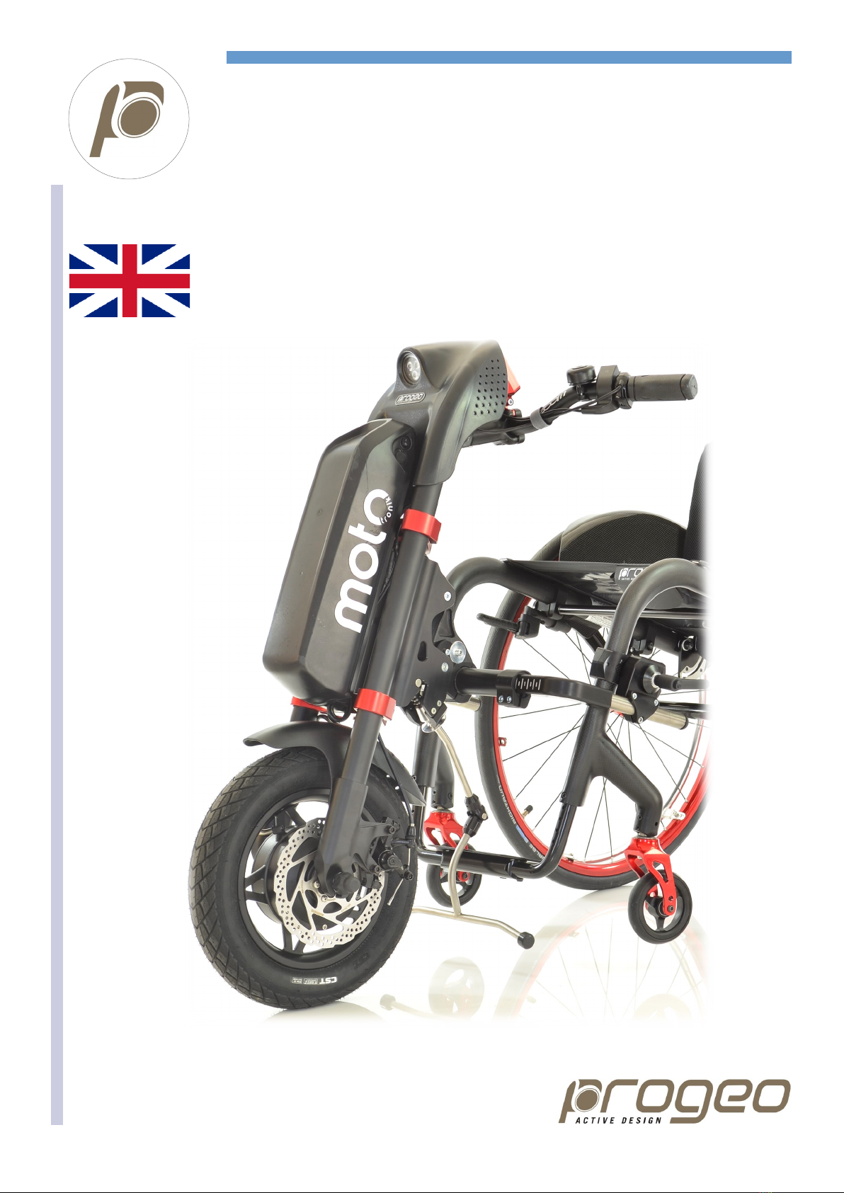
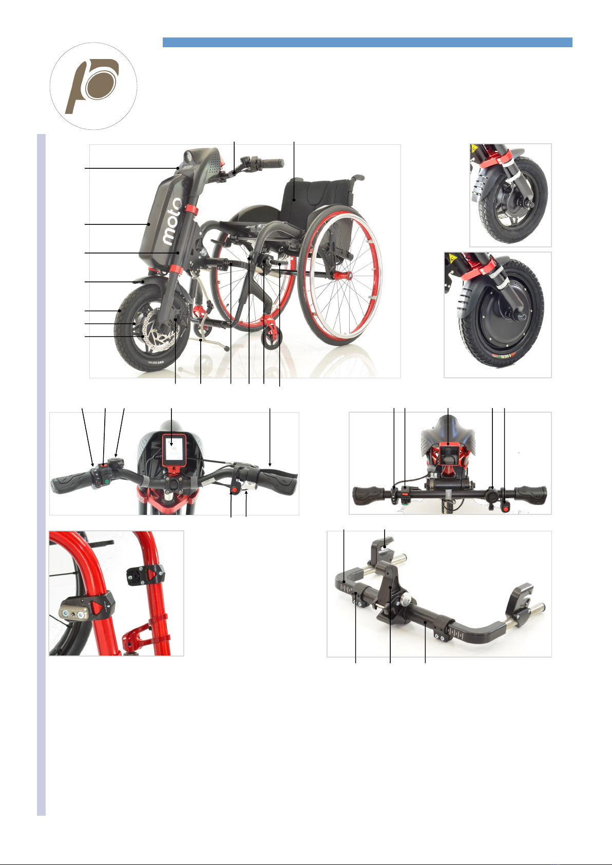
MOTOTRONIK
GENERAL WARNINGS
ANY ADJUSTMENT CAN BE CARRIED OUT EXCLUSIVELY BY QUALIFIED AND AUTHORIZED
BY REHATEAM S.R.L. PERSONNEL.
It is forbidden to carry out any modifications to the Mototronik, even when possible, to the original
design.
Any adjustments and/or any modification that is carried out by non-authorized personnel will
immediately void the warranty on the product and it relieves Rehateam s.r.l. from any responsibility
on any malfunctioning and/or damage due to such adjustments/modifications.
Always contact Rehateam s.r.l. and its technicians for any non-standard requirements or
modifications to allow them to evaluate such modifications and verify that they will not compromise
the normal and safe use of the wheelchair.
Any adjustment of the Mototronik could seriously compromise the safe use of the combination with
the wheelchair causing damage to both the user and the wheelchair itself.
After every adjustment made to the Mototronik, check carefully that all parts are correctly fixed.
Check that all screws and nuts are tightened and that all moving parts are functioning correctly.
After any adjustment, always test the Mototroink combined to with wheelchair before giving the
product to the user.
Rehateam s.r.l. disclaims any responsibility for damage to the product, to any object or to people
due to any modification that is not properly performed or that, in any case, does not guarantee
safety to the user.
The Mototronik device is compatible with most of the manual wheelchairs in the market, neverthe-
less, it is always advisable to consult Rehateam s.r.l. and/or the wheelchair’s manufacturer to know
about the actual compatibility or possible directions to be followed.