Progres 06730001 User manual

Weather Station
CODE 06730001
Manual
The weather station has a set of climatic sensors: relative humidity, temperature, solar
radiation, anemometer, wind vane and rainfall gauge.
The weather station is easy to install, has a watertight connection and is resistant to inclement
weather. It has a metallic structure to hold the dierent devices that the weather station includes
and arms to place the sensors further away from the body, so that they give the correct readings.
All sensors have a 4-20 mA current output, except the rainfall gauge, which has a pulse output
(digital output).
The weather station is connected to the Agrónic with a 12-metre multi-wire cable.
2· User manual | Weather Station
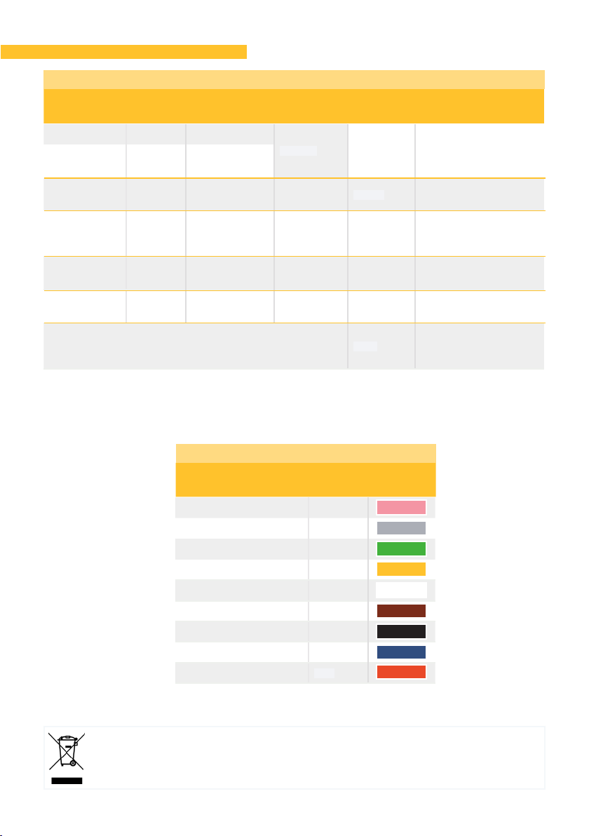
Technical specications
Temperature 4-20 mA -40 to +85ºC
400 ms 1.75 kg
with
protector
Height: 190 mm
Width: 230 mm
Depth: 200 mm
Relative
Humidity 4-20 mA 0 to 100%
Solar
radiation 4-20 mA 0 to 2000
W/m2200 ms 0.1 kg Height: 130 mm
Width: Ø 30 mm
Anemometer 4-20 mA 0 to 120 km/h 2 sec. 0.25 kg Height: 139 mm
Width: Ø 124 mm
(blades)
Wind vane 4-20 mA 0 to 360º (*) 2 sec. 0.25 kg Height: 185 mm
Width: 128 mm
Rainfall
gauge Pulses 0.2 L/m2pulse --- 1 kg Height: 260 mm
Depth: 280 mm
Station complete and assembled with all sensors 7 kg Height: 680 mm
Width: 470 mm
Depth: 570 mm
Temperature Pink
Relative Humidity Grey
Solar radiation Green
Anemometer Yellow
Wind vane White
Rainfall gauge (A) Brown
Rainfall gauge (B) Black
Power supply (+12 Vdc) Blue
Power supply (0 Vdc) Red
Sensor Output
signal Reading range Response
time (min.) Weight Dimensions
Sensor Wire colour
This symbol indicates that electronic devices should not be disposed of along with household
waste at the end of their useful life. The product must be taken to the corresponding collection
point for electronic equipment recycling and correctly processed pursuant to Spanish legislation.
Sensor specifications
Sensor ratio - cable colour
*If the weather station is set up in the Northern Hemisphere, the tare must be adjusted to -20º (Settings - Sensors - Analogue).
*If the weather station is set up in the Southern Hemisphere, the tare must be adjusted to +20º (Settings - Sensors - Analogue).
User manual | Weather Station · 3
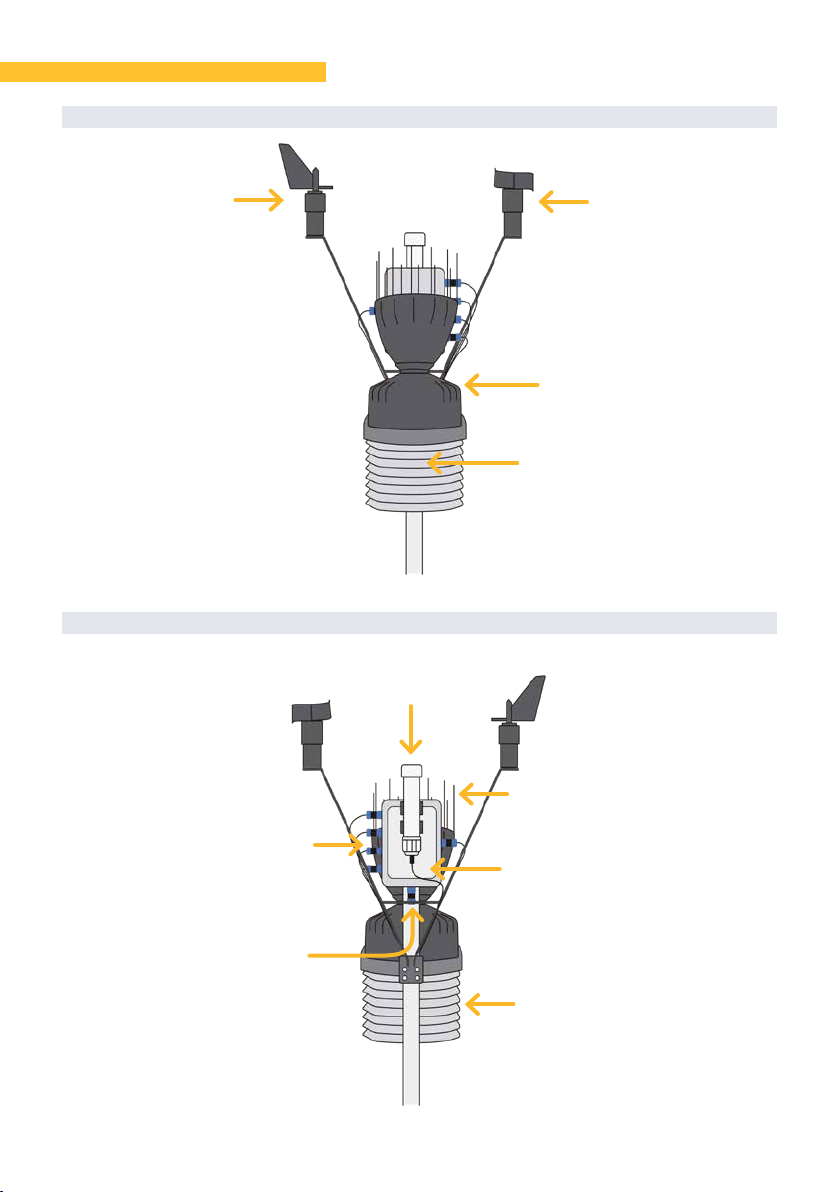
Weather station parts
FRONT VIEW
REAR VIEW
Wind vane Anemometer
Main
connector
Solar
Radiation
Rainfall gauge
Sensor
connectors
Temperature
Relative Humidity
(Both inside the
solar protector)
Solar protector
Anti-bird spikes
Watertight box
connections

4· User manual | Weather Station
Installation
In order to ensure good quality data in the probe reading, it is very important to take a series
of tips into account in the installation as well as to choose the location correctly.
• Move the weather station away from any artificial source of heat or cold.
• The recommended height from the ground is between 1.25 metres and about 2 metres.
• Avoid obstacles such as walls, trees, fences, etc. that may aect the sensor readings. The
weather station should be moved away to a reasonable distance of twice the height of the
nearest object (see example).
• The rainfall gauge must be level and must be mounted on a support so that vibrations are
not transmitted to it.
• For optimal system operation, it is important to ensure the wind vane is oriented correctly.
Depending on the hemisphere in which it is installed, its assembly changes.
8 metres 2 metres
4 metres
NORTH HEMISPHERE
1
2

User manual | Weather Station · 5
Before mounting the weather station, an internal flange must be cut that protects the tipping
container of the rainfall gauge while it is being moved.
Follow the instructions below:
• Remove the "aerocone" to reveal the inside of the rainfall gauge. To do this, turn a little to
the le as shown in the drawing.
• Li the aerocone to see the entire rainfall gauge mechanism.
• Use pliers to cut the flange that prevents the container from tipping, as shown in the
image. To finish, place the "aerocone" again turning to the right.
A B C
C
A
B
SOUTHERN HEMISPHERE
RAINFALL GAUGE
1
2
IMPORTANT
Assemble in the direction of the figure and in the position of the figure .
1 2
6· User manual | Weather Station
Sensor conguration
The sensor, with analogue output, acts by delivering a current and a voltage proportional
to what it measures. The format indicates the sensor units and the relationship between the
voltage read by the input and the sensor reading values.
To configure the sensors of the weather station, go to:
• Function | Settings | Sensors | Analogue
Depending on the controller, once in and for each of the sensors, configure the data according
to the following tables.
ANALOGUE SENSORS
Configuration of the analogue sensors in Agrónic 2500
Sensor Number
Sensor
Number
Input (1)
Number
Input (2)
Time
voltage (2)
Number
Format
Voltage
(Vdc)
Temperature 1 00001 30101 500 ms 1
12 Vdc
Humidity 2 00002 30102 500 ms 4
Anemometer 3 00201 30103 2 s 5
Wind vane 4 00202 30201 2 s 16
Solar radiation 5 00203 30202 250 ms 2
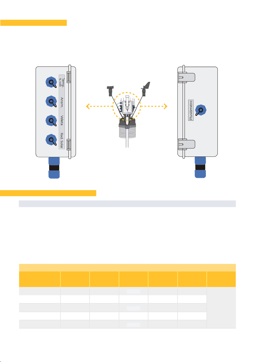
Connections
The box has a series of connectors prepared and identified to screw in their respective sensors.
The connector layout is as follows:
LEFT PROFILE RIGHT PROFILE
1Configure when the weather station is connected directly to the Agrónic 2500.
2Configure in the Agrónic 2500 when the weather station is connected to the AgroBee-L 3MA modules.

User manual | Weather Station · 7
Configuration of analogue sensors in Agrónic 4000/5500
Sensor Number
Sensor
Number
Input
Number
Format
Voltage
(Vdc)
Temperature 1 1 1
12 Vdc
Humidity 2 2 4
Anemometer 3 3 5
Wind vane 4 4 16
Solar radiation 5 5 2
Internal configuration of analogue sensors in Agrónic Bit
Sensor Number
Sensor
Number
Input
Number
Format
Time
Reading (s)
Number
Output *
Voltage
(Vdc)
Humidity 1 00001 4 1.0" 00101
12 Vdc
Temperature 2 00002 1 1.0" 00101
Solar radiation 3 00004 2 0.4" 00002
Anemometer 4 00005 5 2.0" 00003
Wind vane 5 00006 16 2.0" 00001
Analogue Sensor Formats
Setting Humidity
Temperature
Solar Anemometer Wind vane
No. of integers 3 2 4 3 3
No. of decimals 0 1 0 0 0
Sign no yes no no no
Units % ºC W/m2km/h º
Calibration Point 1
Real value 800 mV 800 mV 800 mV 800 mV 800 mV
Logical value 000% - 40ºC 0000 W/m20 km/h 0º
Calibration Point 2
Real value 4000 mV 4000 mV 4000 mV 4000 mV 4000 mV
Logical value 100% 85.0ºC 2000 W/m2120 km/h 360º
Two calibration points must be configured for the sensor calculation from the controller menu
as follows.
From the Agrónic Bit menu, go to:
• Function | Settings | Sensors | Analogue | Formats
Once in, the settings should be the same as shown in the following table.
*This digital output number is used to power the sensor for a configurable time.
IMPORTANT
In the controllers, modify the values of format number 1, since by default it is configured for
another type of temperature sensor.

8· User manual | Weather Station
The rainfall gauge sensor, with pulsed digital output, determines the litres/m2of rain
accumulation.
To configure the weather station's rainfall gauge, go to:
• Function | Settings | Sensors | Counters (Agrónic 2500, 5500, Bit)
• Function | Settings | Sensors | Digital | Function 35 (Agrónic 4000)
Once in, configure the settings according to the following table.
DIGITAL SENSOR
Rainfall gauge sensor format
Setting Value to
configure
Sensor 1
Input No.
*1
Pulse value 00000.20 L
Maximum time
between pulses 600"
Flow in 000.00 L/h
Accumulated in 000.00 L/m2
Text Rainfall
gauge
IMPORTANT
In the Agrónics 2500/5500 and Bit, check that the digital input is configured to work as a rainfall
gauge. This configuration varies depending on the controller.
From the Agrónic 2500/5500 menu, go to:
• Function | Settings | Sensors | Counters
‒Type: rainfall gauge
From the Agrónic Bit menu, go to:
• Function | Settings | Installer | Misc
‒Input D1: rainfall gauge
*In the Agrónic 4000, the digital input must be 12.
Compatibility table
✅ ✅ ✅ ✅
✅ ✅
AGRÓNIC 2500 AGRÓNIC 4000 AGRÓNIC 5500 AGRÓNIC 7000 AGRÓNIC BIT
AgroBee-L AgroBee A. MONOCABLE AGRÓNIC RADIO

User manual | Weather Station · 9
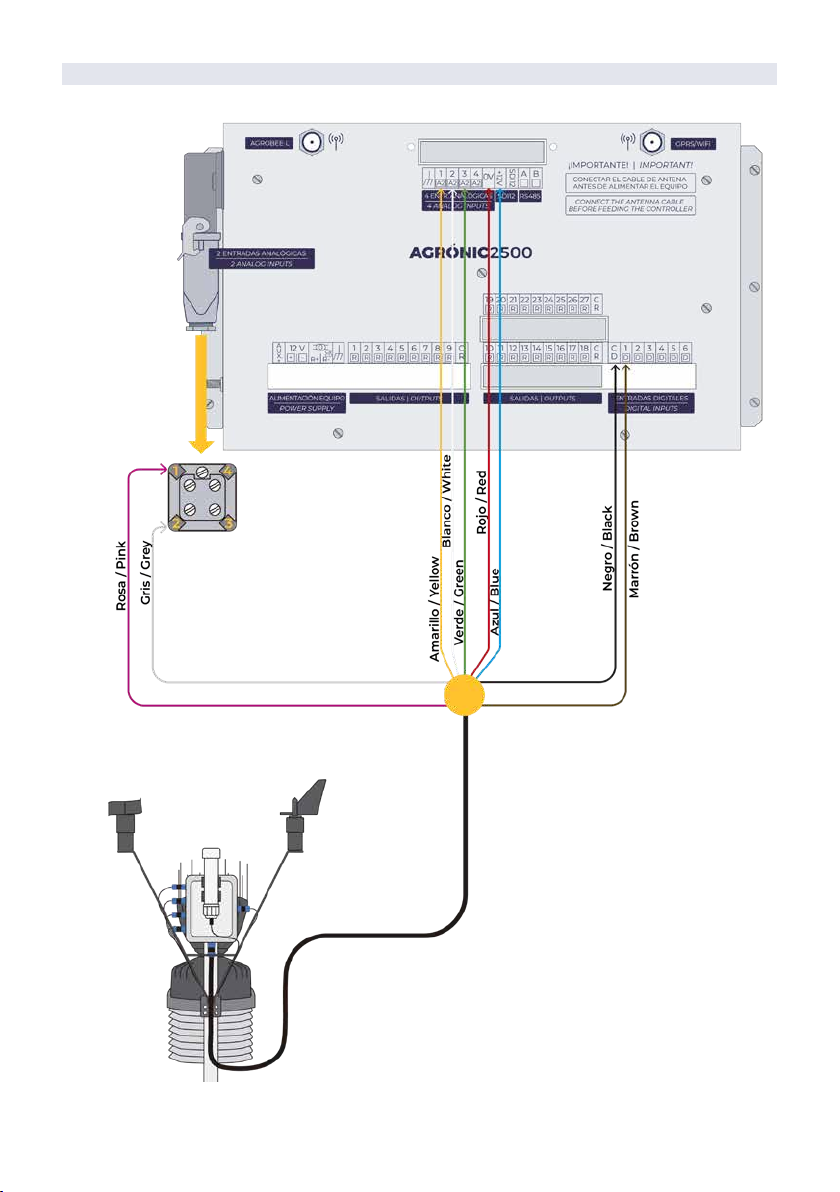
Connection examples
AGRÓNIC 2500 BOX MODEL
Four analogue
inputs
Two
analogue
inputs
IMPORTANT
Maximum cable length between station and controller: 200 m (minimum section 0.5 mm2).
10 · User manual | Weather Station
AGRÓNIC 2500 RECESSED MODEL
IMPORTANT
Maximum cable length between station and controller: 200 m (minimum section 0.5 mm2).

User manual | Weather Station · 11
AGRÓNIC 4000
In the Agrónic 4000, the rainfall gauge must be
connected to digital input number 12.
IMPORTANT
Maximum cable length between station and controller: 200 m (minimum section 0.5 mm2).

R-2364
Polígon Industrial, C/ de la Coma, 2 | 25243 El Palau d’Anglesola | Lleida | España
Sistemes Electrònics Progrés, S.A.
Problem resolution
Maintenance
THE RAINFALL GAUGE DOES NOT COUNT OR ACCUMULATE ANY DATA
THE SENSOR(S) ARE NOT READING ANYTHING
• Check that the flange that protects the tipping container inside the rainfall gauge has been
cut. (P. 5)
For correct operation, some of the sensors require annual maintenance.
• Rainfall gauge:
- Remove the leaf filter and remove any solids that may be clogging it.
- Clean the scoop, the funnel hole in the cone, and the drains in the base.
• Solar radiation: It may be necessary to clean the top dome due to any dirt deposits. In this
case, clean with a damp cloth with water, alcohol or a non-abrasive product.
• Check that the sensors are well connected to the connection box. (P. 6)
TWO MODULES AGROBEE-L 3MA
Module 1
AgroBee-L 3MA
Module 2
AgroBee-L 3MA
In this special model, the connection with the two AgroBee-L 3MA modules is made directly
with two cables with connectors.
IMPORTANT
Maximum cable length between the station and AgroBee-L 3MA: 50 m (minimum section 0.5 mm2).
Table of contents
Popular Weather Station manuals by other brands


ECOWITT
ECOWITT HP2551CA Operation manual

La Crosse Technology
La Crosse Technology WS-9049 instruction manual

HoMedics
HoMedics EnviraStation DWS-220 Instruction manual and warranty information

TFA
TFA KlimaLogg Pro Pavouk DTHL manual

Emos
Emos E8826 manual

La Crosse Technology
La Crosse Technology WS-9031U instruction manual