TFA KlimaLogg Pro Pavouk DTHL User manual

30
LCD display
Buttons Battery
co part ent
Stand (fold out)
Hanging hole
FEATURES:
•
Indication of the current te perature and hu idity
•
DCF radio controlled ti e and date
•
MIN/MAX values and ti e of reception
•
Indication of the current dew point
•
Te perature display in ºC/ ºF
•
12 or 24 hour ti e ode
•
Ti e zone option ±12 hours
•
LCD contrast selectable
•
Low battery indicator
•
Data logging function – up to 50000 data records
•
Logging intervals 1, 5, 10, 15, 30 inutes or 1, 2, 3, 6 hours
•
Data sets can be called up either directly on the device or using a
PC
•
Display of the data sets that have not yet been read out in %
•
Up to 8 trans itters receivable (te perature and hu idity
trans itter or only te perature trans itter with external cable
sensor)
•
Text display with predefined serial nu ber or individual na e
assign ent for trans itters that have been received
•
Manual learning function for all trans itters or individual
trans itters
•
Status display upon loss of trans itter signals
•
Data transfer via USB wireless transceiver

31
•
Individual alar li its for all channels can be set with visual and /
or acoustic alar
•
Additional generat of “Alar Event” data sets when an alar is
triggered
•
Switching output for alar output to external hardware
•
Table standing or wall ounting
•
Including easy-to-use Windows software
ADDITIONAL TRANSMITTER (pur hased separately)
You have the possibility to receive up to eight additional external
trans itters with your Kli aLogg Pro. These are separately available in
specialist shops.
INSTALLATION AND REPLACEMENT OF THE BATTERIES:
Note:
f you have purchased external transmitters, you should insert the
batteries into the transmitters just before into the KlimaLogg Pro. For
more information, please have a look at the chapter “transmitters” of this
manual or refer the instruction manual of the transmitter.
The instru ent operates with three 1,5 V batteries Type Mignon AA.
For installation and replace ent of the batteries, please follow the steps
below:
Te perature & Hu idity
Kat. No.: 30.3180.IT
Te perature with external cable
Kat. No.: 30.3181.IT

32
1. Insert finger or other solid object
in the space at the botto
center of the battery
co part ent and lift up to
re ove the cover.
2. Insert the batteries, pay
attention to their correct polarity.
3. Insert co part ent cover and
close it.
FIRST INSTALLATION:
When the Kli aLogg Pro is powered up, a short beep will sound and all
LCD seg ents will light up.
The Kli aLogg Pro shows the current te perature and hu idity values.
“INDOOR” is displayed in the text field, and 00:00:00 and 01.01.10 are
displayed in the ti e and date area (the device counts up the ti e until
the DCF signal has been received or the ti e and date are anually
set).
After the Kli aLogg Pro has been started up, it searches for external
trans itters for three inutes. After a battery change, the trans itters
that were entered previously are once again assigned the channel that
had previously been assigned to the . External trans itters that had not
been previously detected are auto atically entered on a available
channel.
DCF RADIO CONTROLLED TIME RECEPTION
•
After the Kli aLogg Pro has searched for external trans itters for
three inutes, the device begins to search for the DCF signal
(ger an radio-controlled clock signal), and the DCF reception
indicator flashes. If the ti e code has been received after 5-10
inutes, the radio-controlled ti e is displayed and the DCF
reception indicator re ains on the LCD.
Battery
co part ent
Connector socket
Open Collector

33
•
In case the clock cannot detect the DCF-signal (for exa ple due to
disturbances, trans itting distance, etc.), the ti e can be set
anually.
•
The clock will then work as a nor al quartz clock. (see: Basic
settings/Ti e and calendar).
•
The radio controlled clock receives the signals at 2:00 and 3:00
o'clock in the orning.
•
As soon as the clock has received the DCF signal, the anually
set ti e will be overwritten by the DCF ti e.
•
Note that during reception of the radio-controlled clock signal, no
co unication with the USB wireless transceiver is possible or
ay be briefly interrupted.
Note for Radio Controlled Time DCF:
The base for the radio controlled time is a Caesium Atomic Clock
operated by the Physikalisch Technische Bundesanstalt Braunschweig
which has a time deviation of less than one second in one million years.
The time is coded and transmitted from Mainflingen near Frankfurt via
frequency signal DCF-77 (77.5 kHz) and has a transmitting range of
approximately 1500 km. Your Logger receives this signal and converts it
to show the precise time in summer or wintertime. The quality of the
reception depends greatly on the geographic location. n normal cases,
there should be no reception problems within a 1,500 km radius around
Frankfurt.
Recommended distance to any interfering sources like computer
monitors or TV sets is a minimum of 1.5 - 2 metres.
Within ferro-concrete rooms (basements, superstructures), the received
signal is naturally weakened. n extreme cases, please place the unit
close to a window and/or point its front or back towards the Frankfurt
transmitter.
During night-time, the atmospheric disturbances are usually less severe
and reception is possible in most cases. A single daily reception is
adequate to keep the accuracy deviation below 1 second.

34
LCD DISPLAY:
The LCD display is split into 7 sections.
The designation of each section can be found on the following figure:
BUTTONS:
The logger is equipped with 7 function buttons:
Channel Display
Indication of the trans itters that
were entered, status
infor ation, current selected channel
Text Display
Indication of the channel’s na e
(or serial nu ber) or guidelines
Indication Hu idity
Indication Te perature
Me ory Indication
Indication of the logging interval
and display of the data sets that
have not yet been read out in %
Indication of ti e and date
Toolbar
DCF sy bol, Alar sound,
Alar ON/OFF, USB, History (HIST)
and Learning Mode (LRN)-Sy bol

35
FUNCTIONS OF THE BUTTONS IN THE NORMAL VIEW:
History / Delete go to the history- ode of the recorded data sets
USB (single press)
initiate the contact with the known USB
transceiver
(press and hold for three se onds)
Synchronization to an USB transceiver
SET (single press)
go to the setting ode of the trans itter (Learn
ode).
With a further press you go to the record interval
setting.
(press and hold for three se onds)
go to the basic setting ode of the logger
Alarm (single press)
deactivate active alar sound if an alar is
happend
(press and hold for three se onds)
go to the alar setting ode of the currently
displayed channel.
OK / Max.Min. call up the Max.Min. values and the current dew
point of the selected channel
Plus Scroll up through the available channels
Minus Scroll down through the available channels
BASIC SETTINGS:
In nor al ode, press and hold the SET button for 3 seconds to enter
the anual setting ode for the following functions:
- LCD contrast
- Ti e zone
- Alar sound ON/OFF

36
- Radio-controlled ti e reception ON/ OFF
- 12/ 24 hour for at
- Te perature unit (°C/ °F)
- Manual ti e setting
- Manual date setting
- Main reset
After you press and hold the SET button for three seconds, you are
auto atically taken to the first setting option for basic settings, the
contrast setting. Pressing the SET button once again takes you to the
next setting option.
If no button is pressed for 20 seconds, the Kli aLogg Pro auto atically
switches back to the nor al view. You can return to the nor al view at
any ti e by pressing the “HIST/DEL”, the “USB” or the “ALM” button.
Note:
Changes at the setting-mode require no additional confirmation and are
automatically saved when you leave or go further to the next setting.
f you press and hold the “+” or “-” button, you are quickly taken through
the possible settings (time, date and time zone settings).
LCD- ontrast:
„CONTRAST“ appears on the text display and the default „5“ starts
flashing. With the + or - button you can select between 0 until 7 as
the LCD contrast.
Time zone:
„TIMEZONE“ appears on the text display and the default „0“ starts
flashing.
With the + or - button you can set the ti e zone (-12 until +12
hours).
Alarm sound ON/OFF:
„ALERTSOUND“ appears on the text display and the default “ON”
starts flashing. With the + or - button you can deactivate (OFF) or
activate (ON) the alar sound. If the alar sound is activated, the
alar sy bol will appear (bell) in the toolbar. If the alar sound is
deactivated, the alar sy bol does not appear.

37
Note:
This setting is related to the alarm sound only. Alarms that have been
set, continue to be registered. Also they are shown on the display as
well. Only the sound is activated or inactivated by this setting in case of
an alarm.
Time re eption ON/OFF:
„DCF“ appears on the text display and the default „On“ starts
flashing.
With the + or - button you can deactivate (OFF) or activate (On)
the DCF ti e reception.
12/24-Hour format:
„TIMEFORMAT“ appears on the text display and the default „24 h“
starts flashing. Also the current ti e will be shown in the display.
With the + or - button you can select between 12 hr or 24 hr ti e
for at. If you select the 12 hr ti e for at, AM or PM appears in
the display additionally.
Temperature unit (°C/ °F):
„TEMP UNIT“ appears on the text display and the default „°C“
starts flashing. With the + or - button you can select between „°C“
or „°F“ as the te perature unit.
Manual time setting:
„TIME SET“ appears on the text display and the hour digits start
flashing. With the + or - button you can set the hours.
Press SET button again and set the inutes by the sa e way.
Manual date setting:
„DATE SET“ appears on the text display and the year starts
flashing. With the + or - button you can set the year.
Press SET button again and the onth starts flashing. With the +
or - button you can set the onth.
Press SET button again and the day starts flashing. With the + or -
button you can set the day.
Main reset (resetting ba k to fa tory settings):
“MAIN RESET” appears on the text display. If the “OK/MAX.MIN.”
button is now pressed and held for three seconds, the Kli aLogg
Pro deletes all settings and recorded data. The Kli aLogg Pro is

38
reset to factory settings. After the “OK/MAX.MIN.” button has been
pressed and held for three seconds, the progress of the reset is
shown in % on the e ory display. The Kli aLogg Pro
auto atically restarts when the reset is co plete.
Note:
Note that through the main reset also all recorded data will deleted. f
necessary, please ensure that there is no relevant data on the
KlimaLogg Pro that has not yet been retrieved or transferred to the PC.
f the device shows a malfunction, we recommend that you firstly check
the batteries and try a normal reboot of the unit. f this does not help, we
recommend that you do the main reset.
TRANSMITTERS:
•
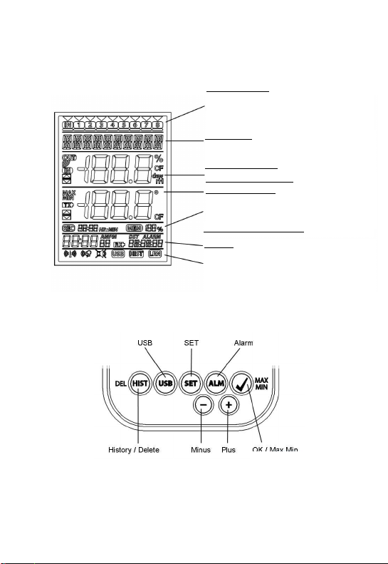
If you use your logger with additional trans itters that were entered
into the logger during startup or via the learning ode, you see a
nu ber in the channel display for every assigned channel.
•
After inserting the batteries in to the trans itter, the trans itter
auto atically starts transferring the outdoor values.
•
After successful start up of the trans itter close the battery
co part ent carefully.
•
In the nor al view and as well as in history ode, you can scroll
up and down through the existing channels by pressing the + or -
button. A triangle is displayed above the currently selected channel
sy bol, and the current channel values are displayed in the
te perature and hu idity display area.
•
The co patible external trans itters (Kat.Nr. 30.3180.IT and
30.3181.IT) each have their own predefined serial nu bers (four-
digit, alphanu eric). This serial nu ber is printed on the respective
trans itter and is also briefly displayed on the trans itter’s display
when it is started up. The serial nu ber is also displayed on the
text display (if the trans itter has been selected as the current one
on the Kli aLogg Pro). The PC software allows you to assign an
individual na e to each channel (except for the logger’s own
easured values. The na e “INDOOR” is always displayed with
these values.)
Note:
f you do not know for certain which transmitter is entered for which
channel in your individual channel designations, you can call up this

39
information in learning mode. n learning mode, the serial number of the
entered channel is always displayed for the corresponding channel.
In the channel display, a status infor ation sy bol can be displayed for
every trans itter. It is a bar that is displayed under the channel nu ber.
If the bar flashes, the batteries of the corresponding trans itter are weak
and should be replaced (in this case, a “TX” sy bol also appears in the
te perature display area when the corresponding channel is
selected/displayed). If a bar is displayed constantly, radio contact to the
corresponding trans itter has been interrupted.
Note:
After the batteries of a transmitter are changed, we recommend
activating the comprehensive transmitter search in learning mode in
order to re-establish contact as quickly as possible.
A transmitter can be entered into a receiving device for only three hours
after it is started up. The transmitter then only transmits its current
measured values and can no longer be entered on a receiving device.
LEARNING MODE:
Learning ode allows you to anually start a trans itter search. It is
possible to enter a trans itter individually on every channel. Further ore
a trans itter that was already entered can be re oved.
•
Press SET button to enter setting ode.
•
CH1-8 and LRN appear in the display.
•
The channel nu bers start flashing.
•
If a trans itter is already entered on a channel, a triangle is
displayed above the corresponding channel nu ber.
Comprehensive hannel sear h
•
Press the OK/MAX/MIN button to start a co prehensive
trans itter search.
•
LEARNING and the channel nu bers appear on the display
with a black bar.
•
The Kli aLogg Pro searches for trans itter signals for three
inutes.
•
If a trans itter signal is received, the bar under the
corresponding channel nu ber disappears.
•
Trans itters that have already been entered re ain, and
trans itters that were previously unknown are successively
assigned.

40
Transmitter sear h for a ertain hannel
•
Press + or - button during CH 1-8 appears in the display.
•
You can select now any channel.
•
The chosen channel nu ber starts flashing.
•
After the desired channel is selected, CH x appears on the
display.
•
---- appears on the display if no trans itter is found, or the
serial nu ber of a trans itter appears if a trans itter is
already entered on that channel.
•
Press the OK/MAX/MIN button to start a trans itter search
for that channel.
•
LEARNING and the channel nu bers appear on the display
with a black bar.
•
The Kli aLogg Pro searches for trans itter signals for three
inutes.
Delete transmitter:
•
Press HIST/DEL button during CH1-8 appears in the display.
•
All entered trans itters will be deleted.
•
DELETED appears in the display.
•
You can also delete single trans itters with the HIST/DEL
button.
RECORDING INTERVAL SETTING:
•
Press SET button twice in nor al ode.
•
INTERVAL appears on the text display.
•
The recording interval indication next to sy bol REC starts
flashing.
•
Default interval 0:15 HR:MIN correspond 15 inutes.
•
The “+” or the “-” button allows you to select the recording
intervals listed below:
1 in, 5 in, 10 in, 15 in, 30 in, 1 hr, 2 hrs, 3 hrs und 6 hrs
Note:
This function allows you to set the interval in which the KlimaLogg Pro
records the data sets. The KlimaLogg Pro automatically creates a data
set in the corresponding interval. A data record is a snapshot of all
temperature and humidity values of all channels as well as the current
time and date.

41
The recorded data sets can be called up in history mode or transferred to
a PC using the USB wireless transceiver.
MAX./MIN VALUES AND THE CURRENT DEW POINT in the sele ted
hannel:
•
Press OK/MAX/MIN button in nor al ode.
•
MAX appears in the display and the highest hu idity is
displayed.
•
Press the button again.
•
The highest te perature is displayed.
•
Press OK/MAX/MIN button again.
•
MIN appears in the display and the lowest hu idity is
displayed.
•
Press the button again.
•
The lowest te perature is displayed
•
Press the button again.
•
DEW appears in the display.
•
The current dew point is displayed.
•
The ti e and date when the respective value was deter ined
are also displayed.
•
The corresponding channel nu ber is shown on the channel
display, and the assigned na e or the serial nu ber of an
entered trans itter is displayed.
•
To clear the recorded ax. in.-values, please press and
hold OK/MAX/MIN button for three seconds in any ode.
•
The ax./ in. values will be deleted for all channels.
•
The display shows the current te perature and hu idity at
all channels.
Note:
Max./min. values are not recorded in a data set.
Only the current max./min. values are displayed in the PC software.
ALARM SETTING MODE:
•
Press and hold the ALM button for the three seconds.
•
HIGH AL RH for the selected channel appears in the display.
•
The upper alar li it for the hu idity is flashing.
•
With the ALM button you can select one possible alar li it
after the other:

42
- High li it hu idity („HIGH AL RH“, default 70%)
- Low li it hu idity („LOW AL RH“, default 20%)
- High li it te perature (“HIGH AL °C“, default 40°C)
- Low li it te perature („LOW AL °C“, default 0°C)
•
When displayed, the li it value can be changed by pressing
the “+” or “-” button.
•
In order to activate an alar li it, the “OK/MAX.MIN.” button
ust be pressed while the corresponding li it value is
displayed.
•
If the alar li it is activated, the alar on/off sy bol is
displayed as active on the toolbar (not crossed out).
•
If the alar li it is not activated, the alar on/off sy bol is
displayed as inactive on the toolbar (crossed out).
•
Press and hold + or - button in setting ode, you will enter
fast ode.
•
To enter nor al ode again, press either ALM button again
or press for at least 20 seconds no button.
Alarm fun tion:
•
In case of an alar , Sy bol ALARM (above the date) and
the corresponding channel nu ber flashes. Also the Hi or Lo
Sy bol is flashing if the corresponding channel is shown.
•
If the alar sound is activated, the sy bol (bell) flashes and
the acoustic alar will sound for 2 inutes.
•
Press ALM button to stop the alar sound.
•
The corresponding “Hi” or “Lo” Sy bol and ALARM continue
to flash until the corresponding value is again within the
alar li it or the alar li it is deactivated in alar setting
ode.
Note:
f any alarm limit is activated (no matter which alarm limit or which
channel), “ALARM” is displayed permanently in normal mode (in the time
and date display area).
The alarm sound can be deactivated in the basic settings of the
KlimaLogg Pro if desired.
You can use the USB wireless transceiver and the PC software to easily
make all alarm settings on the PC and transfer those to the KlimaLogg
Pro.

43
ALARM EVENT DATA SET FUNCTION:
•
If an alar is triggered, your Kli aLogg Pro auto atically
creates a special Alar Event data set.
•
Like a nor al data record, this data record contains a
snapshot of all te perature and hu idity values of all
channels as well as the current ti e and date.
•
Also he channel and the value that triggered the alar are
arked in this Alar Event data set.
•
The Alar Event data sets are recorded in addition to the
nor al data sets and are auto atically listed in the history of
nor al data sets.
Note:
The AlarmEvent data records can be displayed in the history mode on
the KlimaLogg Pro and also in the PC software separately.
HISTORY MODE:
You also have the option to read the data sets and the Alar Event data
sets on the Kli aLogg Pro itself.
•
Press HIST/DEL button in nor al ode.
•
HIST appears in the display.
•
The e ory indication is hidden.
•
The values of the latest data set as well as the ti e and date
when this data set was recorded will be shown.
Use the button as follows to navigate in history ode:
„HIST / DEL“ ------------- next / older record
„OK / MAX.MIN.“ -------- previous / recent record
„Minus„ -------------------- Channel change within the selected data
set (to the left)
„Plus“ ----------------------- Channel change within the selected data
set (to the right)
„ALM“ ---------------------- separation of the Alar Event-data sets
„SET“ --------------------- Back to nor al ode
•
To enter the latest Alar Event data set, please press ALM
button in HISTORY-MODE.
•
The channel and the value that triggered the alar and the
corresponding upper or lower li it are also shown.

44
•
With the HIST / DEL or OK / MAX.MIN. button you can toggle
through the different Alar Event-records (if available).
•
If you press the “ALM” button again, you return to the position
of the last showing Alar Event data set in the nor al
HISTORY MODE.
•
Press and hold the “HIST/DEL” or “OK/MAX.MIN.” button for
fast forward scrolling through the data sets (steps of 50).
•
To enter nor al ode again, press either SET button in
HISTORY-MODE or press no button for at least 2 inutes.
PC CONNECTION:
Note:
The required PC software can be downloaded free from the
download age of the TFA home age (www.tfa-dostmann.de).
The Kli aLogg Pro can record up to 50,000 data sets and can also
transfer the to a PC using the included USB wireless transceiver
(Kat.Nr. 30.3175).
A ring e ory is used. That eans that when all data sets have been
written, the oldest existing data sets is auto atically overwritten by the
next new data set. On the e ory indication, the logger displays the
a ount of data sets that has not yet been transferred to a PC (in
percentage).
Syn hronisation:
The Kli aLogg Pro has a USB button. When the PC software requests
that synchronization be started, please press and hold the USB button
on the Kli aLogg Pro for three seconds until a brief beep is heard and
the USB sy bol on the toolbar flashes. The synchronization ust then
be confir ed in the PC software.
If the synchronization is successful, another beep sounds and the USB
sy bol is displayed steadily. The Kli aLogg Pro starts to transfer his
datas to the PC.
Initiate onta t:
Synchronization is only required once in order to assign the logger to the
software. In order to initiate contact to the software during the next start,
it is only necessary to press the USB button once. The Kli aLogg Pro

45
then atte pts to establish the connection for 5 seconds and displays the
assign ent received fro the software on the text display.
For infor ation about the operating of the PC software, we reco end
that you use the anual (which is available as PDF file at the installation
folder of the software) or use the help function in the PC software.
Note:
The data sets that have been recorded are wirelessly transferred to the
PC using the USB transceiver. The average transfer speed is 20 data
sets per second. n extreme cases, it can take almost 45 minutes until all
data sets have been downloaded (when the memory is completely filled).
During radio-clock reception, communication with the USB receiver is not
possible and is interrupted. When reception is successful,
communication is automatically restored again.
OPEN COLLECTOR HARDWARE OUTPUT:
The Kli aLogg Pro has an open collector hardware output.
This output has two switching outputs that react as follows in case of an
alar on channel 1.
Switch point 1, active when the te p. or rH is exceeded on channel 1.
Switch point 2, active when the te p. or rH is undershot on channel 1.
A switch point is active as long as the alar li it is triggered and
deactivated again as soon as the respective value is again within the
standard range or the respective alar setting is deactivated.
The open collector output has a jack for a 3.5 jack plug. The
following drawing shows the configuration.

46
Technical specifications:
Maxi u switching voltage: 24V. DC
Maxi u switching current: 400 A
Note:
Comply with the technical specifications.
Please get sure, while you plug in any external hardware that this unit is
not under electrical power.
We assume no liability for damage to the KlimaLogg Pro due to incorrect
use of the hardware output or for external devices that are connected.
Ja k
swit h point 1
- high alarm -
swit h point 2
- low alarm -
C = swit h point 1, high alarm
B = swit h point 2, low alarm
A = ground

47
TROUBLESHOOTING:
If proble s occur, we reco end that you read the corresponding
section of the instruction anual in order to beco e fa iliar with the
precise function and principle of operation of the device.
Logger:
When the logger alfunctions, check the batteries and reboot the device
if necessary.
We reco end that you allow the Kli aLogg Pro to rest for several
inutes and then insert the batteries again.
Do not use rechargeable batteries. 1.5 V batteries should be used for
proper function of the Kli aLogg Pro.
Radio trans ission proble s:
Radio trans ission proble s can be occurred between the Kli aLogg
Pro and a trans itter or between the Kli aLogg Pro and the USB
transceiver if local conditions influence the radio signal.
A axi u trans ission range of up to 100 eters to a trans itter and
up to 10 eters to the USB transceiver is possible (free field in each
case). In practice, the axi u possible range is reduced to the actual
range due to local conditions.
Conditions that reduce the range are:
Batteries:
Weak or alfunctioning batteries can decrease the ideal trans ission.
Visible obstacles:
Each visible obstacle has a corresponding negative effect on reception
depending on its thickness, structure and aterial properties. Large
etal and steel surfaces should be avoided if possible (including
coated/da pened window panes).
Invisible obstacles:
The ost co on cause of proble s is interference due to electronic
factors. In this regard, so e distance should be aintained to large
electronic devices (1-2 eters) in order to avoid electro agnetic
influences as far as possible. Any other wireless products that operate
within the range of the device can also have a negative influence on the
trans ission contact.

48
When loss of radio contact occurs, consult the corresponding section of
the instruction anual in order to re-establish contact. If contact cannot
be re-established, or if it should be repeatedly interrupted, check the
general function of your devices when they are placed i ediately next
to each other. If the function of the devices is generally possible, but the
trans ission at the desired location(s) is not reliable, we reco end
changing the location of the logger and/or the trans itter/receiver in
order to opti ize the connection.
PC-Software:
Note that there is a help function within the PC software and that an
instruction anual is included as a PDF-File within the installation folder
of the software.
POSITIONING OF THE LOGGER
The Kli aLogg Pro can be placed on a table or ounted on a wall.
Before ounting it on a wall, ensure that any trans itters in use can be
correctly received at the desired ounting location.
1. Attach an appropriate screw (not included in
the scope of delivery) to the wall and
ensure that its head is approx. 5 fro
the wall.
2. Fold in the logger’s table stand and hang it
on the screw using the eyelet on its back.
Ensure that the device is securely engaged
with the screw before letting go.
CARE AND MAINTENANCE
•
Clean the instru ent and the trans itter with a soft da p cloth. Do
not use solvents or scouring agents. Protect fro oisture.
•
Re ove the batteries if you do not use the product for a lengthy
period.
•
Keep the instru ent in a dry place.
Table of contents
Other TFA Weather Station manuals

TFA
TFA WeatherHub 30.3312.02 User manual

TFA
TFA 30.3196 User manual

TFA
TFA Weather Station User manual

TFA
TFA 35.1102 User manual

TFA
TFA Studio 35.1085 User manual

TFA
TFA 30.5042 User manual

TFA
TFA FAKTUM 35.1101 User manual

TFA
TFA 35.1065 User manual

TFA
TFA 30.3030.IT User manual

TFA
TFA RAIN PRO User manual
Popular Weather Station manuals by other brands

Campbell
Campbell RAWS-H Remote instruction manual

Oregon Scientific
Oregon Scientific Magic BA2000 user manual

Oregon Scientific
Oregon Scientific WMR500 user manual

La Crosse Technology
La Crosse Technology WS-3610-SAL Quick setup guide

Gill Instruments
Gill Instruments MetPak RG 1723-3B-2-111 user manual

Bresser
Bresser 7000016000000 instruction manual