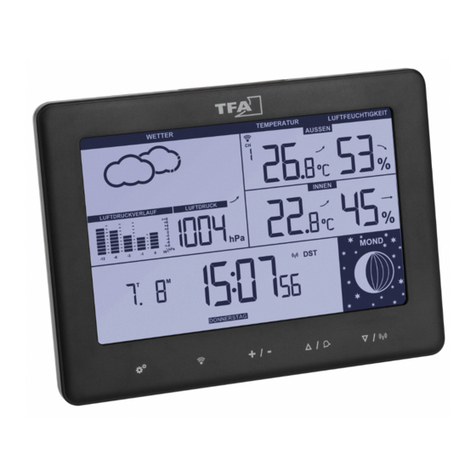
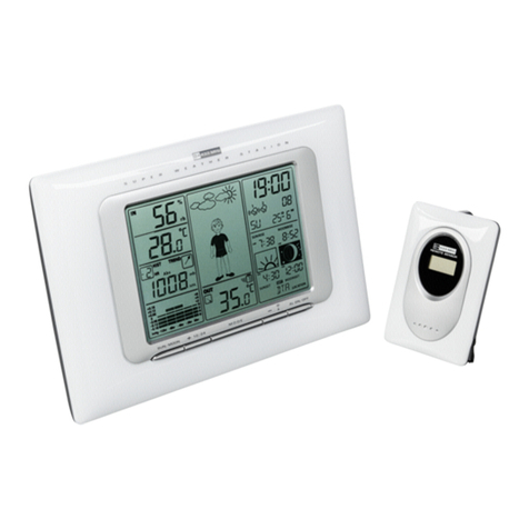
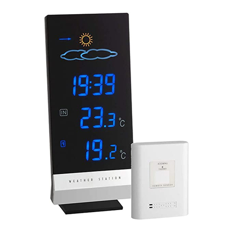
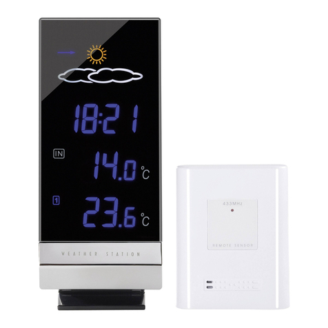
TFA 35.1032 User manual

POSITIONING THE OUTDOOR TEMPERATURE TRANSMITTER
The Temperature Transmitter is supplied with a holder that
maybe attached to awall with the three screwssupplied.
Before securing the transmitter, ensure that the 433MHz
signal(outdoor temperature readings) is properlyreceived.
To attach to the wall, please followthe stepsbelow:
1. Markthe wall using a pen through the holes in the
holder to obtain the exact drilling position.
2. Drill holes in the wall at the points marked.
3. Screwholder onto wall.
There is also double sided tape included with the wallmount. On smooth surfaces
this can be used instead of drilling holes. The mounting surface can,however,
affect the transmission range. If for example the unit isattached to apiece of metal,
it maythen either reduce or increase the transmitting range. For thisreason, we
recommend notplacing the unit on anymetal surfacesor in anyposition where a
large metal or highlypolished surface is in the immediate proximity(garage doors,
double glazing,etc.). Choose a sheltered place. Avoid direct rain and sunshine.
Before securing in place, please ensure that the Weather station can receive the
433MHzsignal from the Temperature transmitter at the positions that you wish to
situate them.
The Temperature Transmitter simplyclicks in or out ofthe holder. When inserting or
removing the Temperature Transmitter from the wall holder please hold both units
securely.
CARE AND MAINTENANCE:
•Extreme temperatures,vibration and shockshouldbe avoided asthese may
cause damage to the unit and give inaccurate forecasts and readings.
•When cleaning the displaysand casings, use a soft damp cloth only.Do not
use solvents or scouring agentsas theymaymarkthe LCD and casing.
•Do not submerge the unit inwater.
•Immediatelyremove all low powered batteriesto avoid leakage and damage.
Replace onlywith new batteriesof the recommended type.
•Do not make anyrepair attemptsto the unit.Return it to its original point of
purchase for repair byaqualified engineer. Opening and tampering with the
unit mayinvalidate its guarantee.
•Do not expose the unit to extreme and sudden temperature changes, this
maylead to rapid changes in forecasts and readingsand therebyreduce its
accuracy.
SPECIFICATIONS:
Temperature measuring range
Indoor : -9.9ºC to +59.9ºC with 0.1ºC resolution
(“OF.L” displayed if outside thisrange)
Outdoor : -29.9ºCto +69.9ºC with 0.1ºC
resolution
(“OFL” displayed if outside this range)
Indoor relative humiditymeasuring range: 20% to 95% with 1% resolution
(“- -” displayed ifoutside this range)
Indoor Temperature checking interval : every10 seconds
Indoor Humiditychecking interval : every20 seconds
Outdoor Temperature reception : every5 minutes
Power Supply:
Weather Station : 2 xAA, IEC LR6, 1.5V
Temperature Transmitter : 2 xAAA, IECLR3, 1.5V
Batterylife cycle : approximately12 months
(Alkaline batteries recommended)
Dimensions (L x WxH)
Weather Station (without stand) : 102 x36 x 172 mm
Temperature Transmitter (without holder): 40 x 22 x128 mm
LIABILITY DISCLAIMER:
•The manufacturer and supplier cannot accept anyresponsibilityfor any
incorrect readings and anyconsequences that occur should an inaccurate
reading takeplace.
•This product isnot to be used for medical purposes or for public information.
•This product isonlydesigned to be used in the home asindication of the
future weather and is not 100% accurate. Weather forecasts given bythis
product should be taken onlyas an indication and not asbeing totally
accurate.
•The specifications of this product maychange without prior notice.
•This product isnot a toy.Keep outof the reach ofchildren.
•No partof this manual maybe reproduced without written consent of the
manufacturer.
R&TTE Directive 1999/5/EC
Summary of the Declaration of Conformity: We herebydeclare that this wireless transmission
device does comply with the essentialrequirements of R&TTE Directive 1999/5/EC.
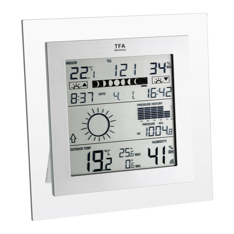
LCD 5 OUTDOOR TEMPERATURE:
The fifth LCD section showsthe outdoor temperature and a transmission signal
reception icon.A number beside the temperature will also showif more than one
transmitter is used.
TOGGLING AND RESETTING THE OUTDOOR RECORDINGS:
1. To toggle between the outdoor current, minimum and maximum temperature
data and the times at which theywere recorded, press the OUT key:
Once to showthe minimum temperature value with time and date recorded
Twice to show the maximum temperature value with time and date recorded
Three times to return to the currenttime, date and temperature level
2. To toggle between transmitters, press the CHANNEL key:
Once to showtransmitter 2
Twice to show transmitter 3
Three times to return to transmitter 1
Note: The transmitter number will only be displayed if there is more than one
transmitter detected.
3. To reset the minimum and maximum outdoor temperature dataand the times
at which theywere recorded, press the OUT keycontinuouslyfor about 3
seconds.This will reset all minimum and maximum data recorded to the
current time, date, temperature. The min/maxtemperature recorded are of
current time and theyremain unaffected bythe time zone setting.
TEMPERATURE TRANSMITTER:
The LCDdisplayshows the current temperature at the location of the transmitter.
The temperature is measured and transmitted to the Weather Station approximately
every60 seconds and at each transmission the antenna icon (Y) will light briefly.
The range of the Temperature Transmitter maybe affected bythe temperature.At
cold temperatures the transmitting distance maybe decreased.Please bear this in
mind when positioning the transmitter. The LCDcontrast on the unit mayalso be
reduced and the batteries are reduced in power.
433MHz RECEPTION:
The Weather station will receive the temperature datawithin 15 minutes. Ifthe
temperature data is not being received 15 minutesafter setting up (the display
shows“---”),then please checkthe following points:
1. The distance of the Weather Station or transmitter should be at least 1.5 to 2
meters awayfrom anyinterfering sources such as computer monitors or TV
sets.
2. Avoid placing the receiver onto or in the immediate proximityof metal window
frames.
3. Using other electrical products such as headphones or speakers operating
on the same signal frequency(433MHz) mayprevent correct signal
transmission and reception.
4. Neighboursusing electricaldevicesoperating on the 433MHzsignal
frequencycan also cause interference.
Note:
When the 433MHzsignal is received correctly,do not re-open the batterycovers of
either the transmitter or Weather Station, asthe batteries mayspring free fromthe
contacts and force a false reset. Should thishappen accidentallythen reset allunits
(see Setting up above) otherwise transmission problems mayoccur.
The transmission range is around 20 - 25 m from the transmitter to the Weather
Station (in open space). However, this depends on the surrounding environment
and interference levels. If no reception is possible despite the observation of these
factors, all system units have to be reset (see Setting up).
POSITIONING THE WEATHER STATION:
The Weather Station comes attached with a removable table stand, which provides
the option of table standing or wallmounting the unit. Before wall mounting, please
checkthat the outdoor temperature can be received from the
desired locations. To wall mount:
1. Fixa screw(not supplied) into the desired wall, leaving the
head extended out the byabout 5mm.
2. Remove the stand from the Weather Station bypulling it
wayfrom the base and hang the station onto the screw.
Remember to ensure thatit locks into place before
releasing.
Outdoor Temperature
in °C
Outdoor Transmission Signal
reception icon
Number showing the
transmitter unit(onlyif
there is more than one
transmitter)
Outdoor temperature

Comfort Indicator Icon
is faultybecause it is not raining. It simplymeans thatthe air pressure has dropped
and the weather is expected to get worse but not necessarilyrain.
Note:
After setting up, readings for weather forecasts should be disregarded for the next
12-24 hours. This will allow sufficient time for the Weather Station to collect air
pressure data at a constant altitude and therefore result in an more accurate
forecast.
Common toweather forecasting, absolute accuracycannot be guaranteed. The
weather forecasting feature is estimated to have an accuracylevel of about 75%
due to the varying areas the Weather Station has been designed for use in. In
areas thatexperience sudden changes in weather (for example from sunnyto rain),
the Weather Station will be more accurate compared to use in areas where the
weather is stagnant most of the time (for example mostlysunny).
Ifthe Weather Station is moved to another location significantlyhigher or lower than
its initial standing point (for example from the ground floor to the first floor ofa
house), remove the batteries and re-insert them after about 30 seconds. Bydoing
this, the Weather Station will notmistake the newlocation as being a possible
change in air-pressure when reallyit is due to the slight change ofaltitude. Again,
disregard weather forecasts for the next 12 to 24 hoursas this will allow time for
operation at a constant altitude.
THE WEATHER TENDENCY INDICATOR
Working together with the weather icons are the weather tendencyindicators
(located on the right hand side of the weather icons).When the indicator points
upwards, it meansthat the air-pressure is increasing and the weather isexpected
to improve, but when indicator points downwards, the air-pressure is dropping and
the weather is expected to become worse.
Taking this into account, one can see howthe weather has changed and is
expected to change.For example, ifthe indicator ispointing downwardstogether
with cloud and sun icons, then the last noticeable change in the weather was when
it was sunny(the sun icon only). Therefore, the nextchange in the weather willbe
cloud with rain iconssince the indicator is pointing downwards.
Note:
Once the weather tendencyindicator has registered a change in air pressure, it will
remain permanentlyvisualized on the LCD.
LCD 4 INDOORTEMPERATURE AND HUMIDITY READING WITH
COMFORTLEVEL INDICATOR:
The indoor temperature and humidityare received automaticallyand displayed on
the fourth section ofthe LCD.
THE COMFORTLEVEL INDICATORS:
Comfortable: A happyface icon “J” indicating a temperature level between
20.0°C and 25.9°C and humiditybetween 45% and 65%.
Uncomfortable: A sad face icon “L” indicating anyvalue outside the
comfortable range.
TOGGLING AND RESETTING THE INDOORRECORDINGS:
1. To toggle between the indoor current,minimum and maximum temperature
and humiditydata and the time of temperature at which theywere recorded,
press the IN key:
Once to showthe minimum temperature and humidityvalues with time of
temperature and date recorded
Twice to show the maximum temperature and humidityvalues with time of
temperature and date recorded
Three times to return to the currenttime, date, temperature and humidity
levels
2. To reset the minimum and maximum temperature and humiditydata and the
times at which theywere recorded,press the IN keycontinuouslyfor about 3
seconds.This will reset all minimum and maximum data recorded to the
current time, date, temperature and humidity. The min/maxtemperatures and
humidityrecorded are of current time and theyremainunaffected bythe time
zone setting.
Indoor Temperature
in °C Indoor Relative
Humidity %

TIME ZONE SETTING:
The time zone default of the Weather Station is 0. To reset the time zone:
1. Press the SET keyafter completing the time setting in order to enter the time
zone setting (flashing).
2. Using the IN key,set the time zone. The range runs from 0 to +9 and then
runsfrom -9 backto 0 in consecutive 1hour intervals.
3. Press the SET keytoenter the date setting mode or do not touch anybuttons
for around 30 seconds to confirm the time zone setting.
DATE SETTING:
Year (flashing) Date (flashing) Month (flashing) Weekday Date
(flashing) (flashing)
The date default of the Weather station is 1. 1. or TH 1. in the year 1998. Once the
radio-controlled time signalsare received, the date isautomaticallyupdated.
However,if the signals are not received, the date can also be set manually. To do
this:
1. Press the SET keyafter completing the time zone setting in order to enter the
year setting (flashing). Reset the year bypressing the IN key. The range runs
from 1998 to 2020.
2. Press the SET keyagain toenter the month and date setting mode (flashing).
3. Using the OUT key, set the month required.Using the IN key, set the date
required.
4. Press the SET keyagain toenter the weekdaysetting (flashing).
5. Using the IN key,set the weekdayrequired.
6. Press the SET keyonce more to confirm all settingsor do not touch any
buttonsfor about 30 seconds. The mode will return to normal.
ALARMSETTING:
1. Press and hold down the ALARM 1 key for around 3 secondsuntil the alarm
time displayflashes.
2. Use the IN keyto setthe hours and the OUT keyto set the minutes. Pressing
these keys continuouslymovesthe hours the minutesconsecutivelyby1 and
minutes by5.
3. Either press the ALARM 1 keyonce more to confirm and return to the normal
displayor do not touch anybuttons for around 30 seconds to confirm the set
time.
4. To activate the alarm function,pressthe ALARM 1 button once for Alarm 1.
You should nowsee the “ “alarm symbol to represent the Alarm 1 being
ON.
5. To de-activate, press the ALARM1button once again.
6. The steps for setting, activating and de-activating Alarm 2 are the same, but
using the ALARM2 button instead of ALARM1.
SNOOZE SETTING AND STOPPING THE ALARM:
1. When the alarm is sounding,press any one ofthe four keys SET, IN, OUT or
SNOOZEto activate the snooze function. The alarm will stop and re-activate
after the snooze interval of5 minutes.
2. To stop the alarm completely,press anyone of the four keys ALARM1,
ALARM2, DATE or CHANNEL.
LCD3 WEATHER FORECASTAND TENDENCY:
The Weather forecasting icons:
There are 3weather icons on the third section of the LCD which can be displayed
in anyof the following combinations:
SunnyCloudywith sunnyintervals Rainy
For everysudden or significant change in the air pressure, the weather icons will
update accordinglyto represent the change in weather. If the icons do not change,
then it means either the air pressure has notchanged or the change has been too
slowfor the Weather Station to register. However, if the icons displayed is a sun or
raining cloud, there willbe no change of icon if the weather getsanybetter (with
sunnyicon) or worse (with rainyicon) since the icons are alreadyat their extremes.
The icons displayed forecasts the weather in to terms of getting better or worse and
not necessarilysunnyor rainyas each icon indicates. For example,if the current
weather is cloudyand the rainyicon is displayed, it does not mean that the product
Time Zone (flashing)

LCD SCREEN AND SETTINGS
For better distinctness, the LCDscreen is split into 5 sectionsdisplaying the
information for time,date, weather forecast, indoors and outdoors.
LCD 1 RADIO CONTROLLED TIME:
The time base for the radio controlled time is a Cesium Atomic Clockoperated by
the Physikalisch Technische Bundesanstalt Braunschweigwhich has a time
deviation oflessthan one second in one million years. The time is coded and
transmitted from Mainflingen near Frankfurt via frequencysignal DCF-77 (77.5 kHz)
and has a transmitting range of approximately1,500 km. Your radio-controlled
Weather Station receives this signaland converts it to showthe precise time in
summer or wintertime.
The qualityof the reception depends greatlyon the geographic location. In normal
cases, there shouldbe no reception problems within a 1500km radius of Frankfurt.
Once the outdoor temperature is displayed on the Weather station,the DCF tower
icon in the clockdisplaywill start flashing in the upper left corner. Thisindicates that
the clockhasdetected that there is a radio signal present and is trying toreceive it.
When the time code is received, the DCF tower becomes permanentlylit and the
time will be displayed.
Ifthe tower icon flashes, butdoes notset the time or the DCF tower doesnot
appear at all,then please take note of the following:
•Recommended distance to anyinterfering sourceslike computer monitorsor
TV sets is a minimum of1.5 - 2 meters.
•Within ferro-concrete rooms (basements, superstructures), the received
signalis naturallyweakened. In extreme cases, please place the unit close to
awindowand/ or point itsfront or backtowards the Frankfurt transmitter.
•During nighttime, the atmospheric disturbances are usuallyless severe and
reception ispossible in most cases. A single dailyreception is adequate to
keep the accuracydeviation below1 second.
MANUAL TIME SETTING:
In case the Weather station is not able to detect the DCF-signal (disturbances,
transmitting distance, etc.), the time can be manuallyset.The clock will then work
as a normal Quartzclock. To set the clock:
1. Press and hold down the SET keyfor about 3 seconds until the time display
flashes.
2. Use the IN keyto setthe hours and the OUT keyto set the minutes. Pressing
these keys continuouslymovesthe hours consecutivelyby1 and the minutes
consecutivelyby5.
3. Either press the set keyonce more to enter the set mode for the time zone
and date section or do not touch anybuttons for around 30 seconds to
confirm the set time.
Note:
The unit will still tryand receive the signal everyhour despite itbeing manuallyset.
When it doesreceive the signal, it will change the manuallyset time into the
received time. During reception attempts the DCF tower icon will flash. Ifreception
has been unsuccessful, then the DCF tower icon will not appear butreception will
still be attempted the following hour.
LCD 2 TIME ZONEAND DATE SETTING:
The second section of the LCD shows either the month and date, the weekdayand
date, Alarm ((1)) time or Alarm ((2)) time. Italso shows the Alarm ON/OFF icons
and
Alarm1 symbol
Time
Calendar
Weather Forecast
Icon
Indoor Relative Humidity %
Comfort Indicator Icon
Outdoor transmission signal
reception icon
Indoor Temperature
in °C
Outdoor Temperature
in °C
DCF Tower Icon
(for time reception)
Weather Tendency
Icon
Minutes (flashing)
Hours (flashing)
Transmitter identification
number

FUNCTION KEYS:
Weather Station:
The Weather Station has8 easyto use function keys; 6 behind the right front panel
of the Weather Station and 2 on the front:
SET key(Setting)
•Used to enter the set mode for the following functions: Time, Time zone,
Year,Dateand Weekday
•The year can also be displayed in the set mode (not displayed in normal
mode)
•Used to activate the snooze function for the alarm
IN key(Indoor)
•Used to toggle between the current /maximum/ minimum indoor temperature
and humidity
•Press for over 3 seconds to reset the indoor maximum and minimum
temperature and humidityrecords (will reset all records to current level)
•Changes the hour, time zone, year, day and weekdaysetting when in set
mode
•Changes the hour setting in alarm setting mode
•Used to activate the snooze function for the alarm
OUT key(Outdoor)
•Used to toggle between the current /maximum/ minimum outdoor
temperature
•Press for around 3 secondsto reset the outdoor maximum and minimum
temperature records (will reset alltemperatures to current level of the relative
transmitter being reset - each transmitter’s data mustbe resetseparately)
•Changes the minute and month setting when in set mode
•Changes the minute setting in alarm setting mode
•Used to activate the snooze function for the alarm
CHANNEL key
•Used to toggle between the outdoor Temperature Transmitters 1, 2 and 3.
•Used to stop the alarm
ALARM 1 key
•Press to displaythe time set for Alarm ((1)) and to simultaneouslyset Alarm
((1)) ON/ OFF
•Press for about 3 seconds to enter the Alarm ((1)) setting mode
•Used to stop the alarm
ALARM 2 key
•Press to displaythe time set for Alarm ((2)) and to simultaneouslyset Alarm
((2)) ON/ OFF
•Press for around 3 secondsto enter the Alarm ((2)) setting mode
•Used to stop the alarm
DATE key
•Used to toggle between the twodate displaymodesand the two alarm times
•Used to stop the alarm
SNOOZEkey
•Used solelyto activate the snooze function for the alarm
SET key
IN key
OUT key
ALARM 1 key
ALARM 2 key
DATE key
CHANNEL keySNOOZE key

However,ensure that you leave 10 seconds in between the reception of the
last transmitter and the set-up of the following transmitter.The Weather
Station will number the transmitters in the order of set-up, i.e. the first
transmitter will have the temperature displayed with the number 1 againstit
and so on.
5. When all the transmitters are set up, there is a testing period, during which
the displayswitches quicklybetween all the received transmitters at random,
according towhich random transmission it receives.Pressing anykeywill
stop this process and the displaywill showthe temperature for the first
transmitter. The process also stops automaticallyif no keysare pressed for a
fewminutes.
6. Once the remote temperature has been received and is displayed on the
Weather Station, the DCF-77 time code reception is automaticallystarted.
This takes typicallybetween 3 - 5 minutes in good conditions.This time
period is an excellent opportunityto locate the transmitter(s) in suitable
location(s) outdoors.In order to ensure sufficient 433 MHztransmission
however, this should under good conditions be no more than 20 - 25 metres
from where the Weather Station will be finallypositioned (see notes on
“Positioning” and “433 MHz Reception”).
7. Ifafter 10 minutes the DCF time has not been received, use the SET keyto
manuallyenter a time initially. The clock will automaticallyattempt each hour
to receive the DCF time. When this is successful,the received time will
override the manuallyset time.The date is also updated with the received
time (Please refer also to noteson “Radio controlled time”and “Manual
time setting”).
HOW TO INSTALL AND REPLACE BATTERIES IN THE WEATHER
STATION The Weather Station uses2 x AA, IEC LR6, 1.5V
batteries. When batteries need to be replaced, the
batterysymbol will appear on the LCD. To install
and replace the batteries,please follow the steps
below:
1. Insert finger or other solid objectin the space
at the bottom center of the battery
compartmentand lift up to remove the cover.
2. Insert batteries observing the correct polarity
(see marking).
3. Replace compartment cover.
HOW TO INSTALL AND REPLACE BATTERIES IN THE
TEMPERATURE TRANSMITTER
The Temperature Transmitter uses2 xAAA, IEC, LR3, 1.5V
batteries. To install and replace the batteries, please followthe
stepsbelow:
1. Unscrewthe screwon the front of the compartment and
remove the cover.
2. Insert the batteries,observing the correct polarity(see
marking).
3. Replace the batterycover on the unitand seal byre-
screwing.
Note:
In the event of changing batteries in anyof the units, all units need to be reset by
following the setting up procedures. This is because arandom securitycode is
assigned bythe transmitter at start-up and thiscode must be received and stored
bythe Weather Station in the first three minutesofpower being supplied to it.
BATTERY CHANGE:
Itis recommended to replace the batteries in all units on an annual basis to ensure
optimum accuracyof these units.
Please participate in the preservation of the environment. Return
used batteries to an authorised depot.

WIRELESS 433 MHz WEATHER STATION
Instructions Manual
INTRODUCTION:
Congratulations on purchasing thisWeather Station withwireless 433 MHz
transmission ofoutdoor temperature and displayof indoor temperature and
humidity, weather forecast iconsand weather tendencyindicators. It isfurther
featuring a DCF-77 radio controlled clockwith calendar displayand two alarms.
With eighteasyto use function keys, this innovative product is ideal for use in the
home or office.
FEATURES:
The Weather Station
•DCF-77 Radio controlled time with manual setting option
•24 hour display
•Hour and minute display,seconds indicated byflashing dot
•Time zone option ±9 hours
•Features 2alarms with snooze function
•Weekdaywith dateor datewith month calendar display
•Weather forecasting with 3weather icons
•Weather tendencyindicator
•Indoor temperature reading in °C with minimum and maximum recording
•Indoor humidityreading displayed as RH% with minimum and maximum
recording
•Indoor comfort level indicator - happyor sad face icons
•Outdoor temperature reading (for up to 3 transmitters) in °C with minimum
and maximum recording
•All minimum and maximum recordings showdateand time of temperature
received and can be reset
•Can take up to three outdoor transmitters
•LowBatteryindicator
•Wall mountable or table standing
THE OUTDOOR TRANSMITTER
•Remote transmission of outdoor temperature to
Weather Station by433 MHz
•Shower proof casing
•Wall mounting case
•Mounting at a sheltered place. Avoid direct rain
and sunshine
SETTING UP:
1. First, insertthe batteries into the Weather station (see “Howto installand
replace batteries in the Weather Station”below). Once the batteries are in
place, all segmentsof the LCD will lightup brieflyand a short signal tone will
sound. Then the indoor temperature and humidity,the time as 0:00, the date
as 1.1. and the weather icons sun and clouds will be displayed. Ifthe indoor
temperature and humidityare notdisplayed after a fewseconds, remove the
batteries and wait for atleast 10 seconds before reinserting them. Once the
indoor data is displayed proceed to step 2.
2. Within 3 minutes of activating the Weather station, place the batteries into the
transmitter (see “How to install and replace batteries in the Temperature
Transmitter” below). The temperature will then be displayed on the small
LCD of the transmitter. Ifthe temperature is not displayed,remove the
batteries and wait for atleast 10 seconds before reinserting them.
3. After a fewsecondsof inserting the batteries into the transmitter, the Weather
Station will start receiving data from the transmitter. The remote temperature
will then be displayed on the Weather Station. Ifthisdoes nothappen after 15
minutes,the batteries will need to be removed from both units and reset from
step1.
4. The Weather Station can take up to 3 remote transmitters. If you have
purchased additionaltransmitters, followstep 2 for all extra transmitters.
LCD display Hanging hole
Battery cover
Function keys Detachable stand
Table of contents
Other TFA Weather Station manuals

TFA
TFA ZENO 35.1163.01 User manual

TFA
TFA IQ-WS 35.1040 User manual

TFA
TFA 30.5027 User manual

TFA
TFA EXACTO User manual

TFA
TFA KLIMA GUARD User manual

TFA
TFA KlimaLogg Pro Pavouk DTHL User manual

TFA
TFA 47.3005 User manual

TFA
TFA 35.1106 User manual

TFA
TFA 35.1163.01 User manual

TFA
TFA MODUS PLUS User manual

TFA
TFA Sigma Plus 35.1063 User manual

TFA
TFA 35.1166.54 User manual

TFA
TFA 35.1134 User manual

TFA
TFA 35.1102 User manual

TFA
TFA CONNECT 35.1143.IT User manual

TFA
TFA QUADRO 35.1098.54 User manual

TFA
TFA AMBIENTE 35.1057 User manual

TFA
TFA Klima@Home 30.3060.01.IT User manual

TFA
TFA 30.3016.54.IT User manual

TFA
TFA 35.1098 User manual