Novalynx 100-1950 User manual

NOVALYNX CORPORATION
MODEL 100-1950
WEATHER STATION
INSTRUCTION MANUAL

Receiving nd Unp cking
Carefully unpack all components and compare to packing list. Notify NovaLynx
Corporation immediately concerning any discrepancy. Inspect equipment to detect any
damage that may have occurred during shipment. In the event of damage, any claim for
loss must be filed immediately with the carrier by the consignee. amages to equipment
sent via Parcel Post or UPS require the consignee to contact NovaLynx Corporation for
instructions.
Returns
If equipment is to be returned to the factory for any reason, call NovaLynx between 8:00
A.M. and 4:00 P.M. Pacific Time and request a Return Authorization Number (RA#).
Include with the returned equipment, a description of the problem and the name, address,
and daytime phone number of the sender. Carefully pack the equipment to prevent
damage or additional damage in the return shipment. Call NovaLynx for packing
instructions in the case of delicate or sensitive items. If packing facilities are not available
take the equipment to the nearest Parcel Post, UPS, or freight service and obtain
assistance with the packaging. Write the RA# on the outside of the box.
W rr nty
NovaLynx Corporation warrants that its products are free from defects in material and
workmanship under normal use and service for a period of one year from the date of
shipment from the factory. NovaLynx Corporation's obligations under this warranty are
limited to, at NovaLynx's option: (i) replacing; or (ii) repairing; any product determined to
be defective. In no case shall NovaLynx Corporation's liability exceed product's original
purchase price. This warranty does not apply to any equipment that has been repaired or
altered, except by NovaLynx Corporation, or that has been subjected to misuse,
negligence, or accident. It is expressly agreed that this warranty will be in lieu of all
warranties of fitness and in lieu of the warranty of merchantability.
Address
Nov Lynx Corpor tion
4055 Gr ss V lley Highw y, Suite 102
Auburn, CA 95602
(530) 823-7185
FAX (530) 823-8997
Copyright © 1997 by NovaLynx Corporation
ii

TABLE OF CONTENTS
SECTION NO. P A G E N O .
1.0 GENERAL DESCRIPTION 1
1.1 Wind Speed nd Direction 1
1.2 Temper ture 1
1.3 Rel tive Humidity 1
1.4 B rometric Pressure 1
2.0 SPECIFICATIONS 2
3.0 INSTALLATION 2
4.0 THEORY OF OPERATION 3
4.1 Temper ture 3
4.2 B rometric Pressure 4
4.3 Rel tive Humidity 4
4.4 Wind Speed 4
4.5 Wind Direction 4
5.0 CALIBRATION 5
5.1 Wind Speed 5
5.2 Wind Direction 5
5.3 Temper ture 5
5.4 Rel tive Humidity 6
5.5 B rometric Pressure 6
6.0 MAINTENANCE 6
7.0 PARTS LIST 7
iii

WEATHER STATION
Model 100-1950
1.0 GENERAL DESCRIPTION
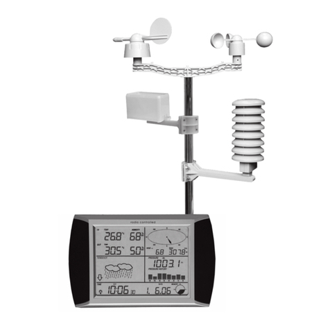
NovaLynx Corporation provides a weather station, Model 100 -1950, that displays Wind
Speed, Wind irection, Temperature, Relative Humidity, and Barometric Pressure. The
weather displays are analog dials that are enclosed in an attractive wood frame suitable
for hanging on a wall.
1.1 Wind Speed nd Direction
The Wind Speed and Wind irection indicators are rectangular electrical meters with
needles that deflect with the changing winds. A combination anemometer and vane wind
sensor is mounted outdoors at an elevation that will give good exposure to the local winds.
The wind sensor is connected to a signal conditioning circuit board located behind the
meter case. The anemometer circuit is self generating while the vane circuit requires an
external power supply.
1.2 Temper ture
The other meters are mechanical devices. The temperature dial is connected to a
remotely located temperature sensor through a capillary tube. The temperature measured
at the end of the tube is indicated by the meter. The remote temperature sensor may be
located to measure either indoor or outdoor air temperatures.
1.3 Rel tive Humidity
The relative humidity dial is a self-contained meter with the sensing element housed inside
the meter. As the relative humidity changes, the meter will respond and its pointer will
indicate the new value.
1.4 B rometric Pressure
Similarly, the barometer dial contains the sensing element and indicates changes in the
atmospheric pressure. A moveable set-point needle allows the operator to determine
whether the barometer has risen or fallen since the last reading has been taken.
1

2.0 SPECIFICATIONS
Sensors:
Wind Speed: AC Generator
Wind irection: 120 ohm Potentiometer
Temperature: Vapor Capillary
Relative Humidity: Bonded Helical Coil
Barometer: Aneroid Cell
Measured Ranges:
Wind Speed: 0-25/25-100 mph
Wind irection: Nine Cardinal Points
Temperature: -40 to +140EF
Relative Humidity: 0 to 100 % R.H.
Barometer: 27 to 32 in. Hg
& 914 to 1086 mb
Wind Sensor Cable: 5 conductor, 20 AWG
Cable Length: 50 feet ( 15 m )
Temperature Tube: 6 ft ( length not extendable )
Front Panel Finish: ark Mahogany
Power requirements: 1 ea " " cell battery
isplay Size: 12" hi x 16.5" w x 3" d
( 305 x 419 x 76 mm )
Weight / Shipping: 16 lbs / 20 lbs
( 7 kg / 9 kg )
3.0 INSTALLATION
Installation of the weather station is relatively simple. The wind sensor and temperature
sensor are mounted outdoors with the wind sensor placed onto a mast and the
temperature sensor clamped onto a wall. The wind sensor has a mounting collar with
locking screws that allow it to be installed onto a 1" O. . mast or pipe. If the sensor is to
be located on the roof of a building, the mast should be located on the upwind side. For
small structures, the mast should be one and one half times as high as the building upon
which it sits. If this is not practical such as is the case for extremely tall buildings, then the
mast should be at least thirty feet high above the roof. The nature of the vane requires that
it be aligned to North. Alignment marks are provided on the sensor housing. Refer to the
sensor manual for specific instructions. Route the wind sensor cable in the most direct
2

manner to the display and connect the five pin IN plug into the matching connector
located on the side of the display panel.
The temperature sensor should be located on the North side of the structure and under an
eave or overhang if possible. The temperature sensor should be protected from exposure
to direct sun light and rain to avoid errors in the readings. If a temperature sensor shelter
is available, place the sensor inside the shelter. The temperature sensor must be installed
by routing the capillary tube from the display to the desired location of the sensor. In many
instances, the display will need to be positioned as close as possible to the outside wall
and next to the temperature sensor installation point. If possible, route the capillary tube
through the nearest window, taking care to avoid bending or deforming the tube in any
manner otherwise errors in the reading will result. If a window is not available, drill a hole
through the wall to get the temperature sensor to the outside. Fill the hole to prevent air
and moisture intrusion. Use a clamp or appropriate hardware to fasten the temperature
sensor to the wall or nearest support structure.
For both the wind sensor and the temperature sensor, the cable and capillary tube must
be secured to prevent being damaged by high winds. Clamp or tie down the wind sensor
cable every two to three feet using either plastic wire ties or other appropriate hardware to
suit the installation and the supporting structure. Secure the temperature sensor tube
being very careful to avoid crimping, sharp bends, and any deformation of the tube.
Please note that the temperature sensor tube contains a fluid and must not be cut open
for any reason. The temperature sensor tube can not be extended in length due to its
design.
Install one each " " cell battery into the battery holder inside the back of the display. The
battery provides power for the wind direction sensor and dial.
Upon completion of the installation of the wind sensor and temperature sensor, hang the
display onto the wall. Use the same methods as those employed to hang pictures. Avoid
placing the display panel near sources of heat and cold and humidity to eliminate errors
in the readings. Place the display at a height that will provide a convenient viewing of the
dials. Be sure to leave a small space behind the display to allow air flow for the relative
humidity sensor to operate properly.
Periodic checking of the sensors and dials will help ensure good readings from the dials.
4.0 THEORY OF OPERATION
4.1 Temper ture
The temperature dial movement is accomplished through the use of a vapor capillary
system. As the temperature at the sensing end increases, an increase in the pressure
inside the capillary tube occurs. The increase in pressure moves the meter pointer. The
3

meter has been designed and calibrated to give readings corresponding to the measured
temperatures.
4.2 B rometric Pressure
The barometer dial incorporates an aneroid cell as the sensing device. The cell
mechanically changes shape as the atmospheric pressure increases and decreases. The
aneroid cell is attached to the meter pointer. The dial mechanism moves the pointer in
relation to the measured pressure. A manually adjustable pointer is used to track whether
the pressure is rising or falling. Whenever a reading is made the pointer is placed over the
aneroid cell's pointer. At the next reading the observer can determine if the new reading
is greater than or less than the previous reading.
4.3 Rel tive Humidity
Relative humidity is measured by a coiled sensor with a special coating that is sensitive to
moisture. As the relative humidity of the surrounding air changes, the coating of the coiled
material either absorbs or releases moisture as it attempts to attain equilibrium with the air.
The coiled material expands with increasing moisture and contracts as the moisture
decreases. Movement of the coiled material is transmitted to the dial pointer and is
calibrated to reflect the relative humidity of the air.
4.4 Wind Speed
Wind speed is sensed by anemometer cups that turn as the wind speed increases above
the starting threshold of the sensor. The cups are coupled to an AC generator that
generates an AC signal as the cups rotate. The AC signal is transmitted by two wires to
the circuit board at the display panel. Electronic components rectify, filter, and scale the
signal into a calibrated C signal to drive the meter. A range switch enables the observer
to select the Low or High range in order to obtain the best resolution when making a
reading. For wind speeds below twenty-five miles per hour, the best reading is obtained
by setting the range switch to the Low position. For wind speeds above twenty-five mph,
use the High range switch position. The AC wind speed signal is not polarized electrically
and therefore reversal of the wind speed wiring will not harm or change the operation of
the signal conditioning circuit.
4.5 Wind Direction
Wind direction is sensed by a moving potentiometer that has been mechanically coupled
to the vane. Changes in the wind direction cause the vane to move the potentiometer. A
C signal from the " " cell battery powers the potentiometer. As the potentiometer moves
it creates a changing C voltage across its resistive element. The changing C signal is
presented at the wiper of the potentiometer and is connected to the signal conditioning
circuit at the display panel. The signal conditioning circuit provides an adjustment for "fine
4

tuning" of the wind direction meter. A three position switch allows the operator to select
the wind direction sensor, the calibration mode, or to disconnect the battery. Whenever
readings are to be made infrequently, it is recommended that the wind direction circuit be
disconnected to increase the life of the battery.
5.0 CALIBRATION
5.1 Wind Speed
Adjust the wind speed circuit by first setting the range switch to the Low range position.
Remove the anemometer cups and attach a wind speed spin-up motor to the generator
shaft. Rotate the shaft at a constant 300 rpm. For the standard wind sensor, the 300 rpm
represents 18.5 mph ( 8.2 m/s ). Adjust the wind speed range potentiometer located on
the signal conditioning circuit. If possible check the circuit operation at a higher wind speed
by rotating the anemometer shaft at one of the higher rpm values shown, such as 600 rpm.
Please note that the anemometer calibration is fixed and is determined by wind tunnel
tests. There is no adjustment as to the mph vs rpm values. Should the anemometer cups
become damaged the response of the cups to the wind will be affected and will result in
errors in the meter readings. Replace damaged cups as soon as possible. Worn
generator bearings can also result in wind speed errors. Replace the anemometer
bearings at least annually, and especially in areas that experience constant wind activity.
5.2 Wind Direction
As the vane rotates in a clockwise direction as viewed from above the sensor, the meter
will increase its reading from zero to 360 to a maximum indication of East. The full-scale
reading will vary as the battery loses its power over time. The full-scale adjustment should
be checked before taking readings, especially if readings are taken infrequently. Set the
front panel switch to the calibration check position. The sensor should be connected to the
meter circuit during this test. Adjust the front panel control until a full-scale reading is
obtained. If it is difficult to make the adjustment, it may be an indication that the battery
needs to be replaced. Notice that the full-scale deflection of the meter is East, or 90
degrees Azimuth.
5.3 Temper ture
The temperature meter and capillary tube do not have any user available adjustments.
The only check that can be made is to place the temperature sensor into a controlled or
stable temperature bath and compare the reading with that of glass thermometer or
another electronic thermometer. For temperature readings that appear to be slightly off
during the temperature check, make note of the difference and apply the value to the meter
readings whenever a reading is taken. Should the temperature reading appear to be
substantially in error the temperature sensor and meter may need replacement. Contact
5

NovaLynx for assistance.
5.4 Rel tive Humidity
Relative humidity has an adjustment screw located at the rear of the meter. Obtain the
local relative humidity by using a mechanical or an electronic psychrometer. Adjust the
screw to obtain the same reading on the humidity dial. Make only minor adjustments to the
meter at any one time. Allow the meter to stabilize for a few minutes and then repeat
should more adjustment be required. An agreement of three to five percent RH should be
acceptable for this type of meter.
5.5 B rometric Pressure
The barometer should be adjusted for the station elevation. Obtain the local barometric
pressure by calling the local airport or by listening to local weather forecasts. Adjust the
screw at the rear of the barometer to obtain the same reading. Follow the local readings
for several days and readjust the meter as required. Make only minor adjustments at any
time. o not use force or turn the screw by a large amount to avoid damaging the
barometer.
6.0 MAINTENANCE
Maintenance of the weather station is limited to keeping the display panel clean and free
of dust. Use only a damp cloth and water to clean the surfaces of the display panel. The
sensors should be free of debris and kept clean. The wind sensor should be checked for
worn bearings, damaged cable, and loose hardware. Periodic inspections should be made
to help maintain the accuracy of the data. Each time a reading is made, check the wind
sensor to ensure that it is rotating freely in the wind and there are no major problems.
6

7.0 PARTS LIST
MODEL 100-1950
WEATHER STATION
PART NO. ESCRIPTION QTY
100-2130 COMBINATION WIN SENSOR 1
100-19501 TEMPERATURE IAL ASSEMBLY 1
92080000 BAROMETRIC PRESSURE IAL 1
92080200 HUMI ITY IAL 1
92080300 WIN SPEE METER 1
92080400 WIN IRECTION METER 1
7
Table of contents
Other Novalynx Weather Station manuals
Popular Weather Station manuals by other brands
Ambient Weather
Ambient Weather WS-1090 user manual
La Crosse Technology
La Crosse Technology Tomorrow's Weather Today WS-7394U-IT instruction manual
Elma Instruments
Elma Instruments DTR 880A user manual
La Crosse Technology
La Crosse Technology 308-1451H instruction manual

Hama
Hama 00092659 EWS-165 operating instructions
TESA
TESA WS2980C-PRO Operation manual


