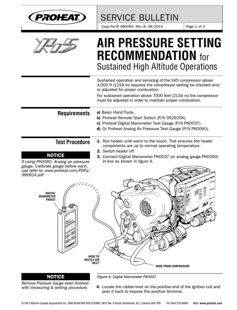
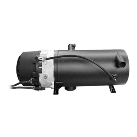
Proheat X45 plus User guide

OWNER’S HANDBOOK

Owner’s Handbook Page 1
Introduction............................................................................................................................... 2
Operating your PROHEAT ......................................................................................................... 3
Optional Sleeper Fan Operation ................................................................................................ 4
Toggle Switch – Timer.............................................................................................................. 5
Timer Instructions..................................................................................................................... 6
Caring for your PROHEAT......................................................................................................... 7
Troubleshooting..................................................................................................................... 12
Troubleshooting – Operation Indicators/Diagnostic Codes ................................................... 13
Troubleshooting – Function Diagnostics............................................................................... 15
Warranty................................................................................................................................. 20
Owner’s responsibility............................................................................................................ 21
Contents

Page 2 Owner’s Handbook
Congratulations on your purchase of a PROHEAT X45 Plus diesel-fired heater. This handbook is provided
to summarize the operation and maintenance of the PROHEAT X45 Plus for the Owner/Operator.
For complete information, please refer to the Installation and Service manual 925860 at www.proheat.com
Although trucks have been used throughout this book, applications for PROHEAT are by no means
limited to trucks. PROHEAT heaters are designed to be used on any diesel equipped vehicle
including: trucks, buses (school, transit and coach), construction equipment, off road equipment,
military equipment and cargo.
PROHEAT heaters are used in the following applications:
• Preheats an engine block to ensure reliable cold weather starting.
It is recommended that PROHEAT is used year round (winter and summer) to reduce engine
wear associated with cold starting.
• With the engine off—supplies heat to the engine and sleeper for comfort and reduced idle time
resulting in cost savings through reduced fuel consumption and engine wear.
• With the engine running—adds heat to the coolant system when the engine does not provide
adequate reject heat for the vehicles interior. PROHEAT can be operated when the engine
is running.
• Provides heat to protect valuable cargo from cold weather damage.
• With the engine off - supplies minimal heat to prevent freezing over long periods of time.
Introduction
Note
eNgiNe Block heat
eNgiNe & Sleeper heat
SupplemeNtal heat
cargo heat
aNti-Freeze heat

Owner’s Handbook Page 3
Your PROHEAT X45 Plus is controlled by either an ON/OFF manual toggle switch or by the optional
PROHEAT 7-day timer. The timer can be controlled manually, or it can be set to start at a predetermined
time. Both devices have a light that indicates when the heater is operational as well as flashing corresponding
diagnostic codes indicated by the PCM. Your installer may have enabled optional features and heating modes.
Please see the X45 Plus Installation and Service manual 928560 or your Dealer for more information.
1. SWITCH ON – The ON/OFF switch (or Timer) lamp and the PCM “ON” LED will light. In addition,
the Hour Meter (Auxiliary Output) will be powered. If the coolant temperature is below 150°F (65°C)
the PROHEAT enters Pre-check. If the coolant temperature is above 150°F (65°C) the PROHEAT
enters Standby.
2. PRECHECK – The PCM performs a short diagnostic cycle. This takes a few seconds to check
components for proper ranges, checking for the presence of a flame, short-circuits and open circuits.
If there are no errors indicated, the PROHEAT goes to “Ignition”.
3. IGNITION –
The blower starts first, followed by the coolant pump, ignition spark, air compressor
and
fuel pump. The ignition electrode sparks for up to 60 seconds. Once the flame sensor detects a good
flame, the PROHEAT goes to “Full Output”. The Sleeper Fan (if equipped) output then turns on.
4. FULL OUTPUT – The PROHEAT runs at Full Output until the coolant temperature reaches 185°F
(85°C) at the heater outlet. The PROHEAT shuts the flame off and goes to “Cool down” (Purge).
5. COOL DOWN (Purge) – The air compressor and fuel pump shut off immediately. The blower and
coolant pump continue to run. After 3 minutes, the blower stops and the PROHEAT goes to “Standby.”
6. STANDBY – The coolant pump circulates the coolant through the system until the temperature
drops to 150˚F (65˚C) at the heater outlet; then it will enter Precheck and repeat steps 2 to 6. The
PROHEAT will continue to repeat steps 2 to 5 until it is switched “off.”
7. SWITCH OFF – If PROHEAT is in Full Output, it will Cool Down (Purge) first, then shut “OFF”.
If PROHEAT is in Standby, it will shut “OFF” immediately.
When switched OFF, the Sleeper Fan (if equipped) output turns off.
When switched OFF, the Hour Meter (Auxiliary Output) will shut off.
Operating your PROHEAT
StaNdard mode
operatiNg SequeNce

Page 4 Owner’s Handbook
Optional Sleeper Fan Operation
Today’s sleepers are designed for maximum comfort for the vehicle operator. Generally the units are
larger and have accessories that compete for battery power with auxiliary heaters. PROHEAT is a
cost-saving component by reducing fuel consumption and engine maintenance. Therefore, it should
be given priority over these accessories.
For more information on Sleeper Fan installation, please refer to the Installation and Service manual
925830 at www.proheat.com
PROHEAT installation recommendations are designed to allow the operator to:
• Run the PROHEAT with the vehicle ignition key in the OFF position
• Set the desired sleeper ambient temperature using the dedicated Proheat thermostat
The vehicle operator’s responsibility is to ensure that:
• Coolant valves used in the heating system are open: These can be manually or electrically
operated (electrically operated valves must be opened before shutting the vehicle OFF)
• When operating the PROHEAT, power consuming accessories such as refrigerators, DVD’s, TV’s,
satellites, heated mirrors, etc. are not used to ensure enough starting amperage for the engine
• Sleeper curtains are closed: The PROHEAT is designed to heat the sleeper and engine as efficiently
as possible – heating the cab, fuel tanks and batteries means longer run time which will require
more battery power
Note

Owner’s Handbook Page 5
Toggle Switch – Timer
T-II Manual
Indicator Light
(Red)
Timer
Indicator Light
(Green)
timer
toggle Switch

Page 6 Owner’s Handbook
T-II
Timer Instructions
STEP 1 Press and Hold “TIMER” (green light
will turn on and “T1” will flash).
STEP 2 Press “ “ or “ “ to set time
STEP 3 Press “DAY” to advance the day.
STEP 4 Release “TIMER”. (green light and
“T1” will remain lit to activate timer).
STEP 1 Press and hold “CLOCK”
STEP 2 Press “ “ or “ “ to set time
STEP 3 Press “DAY” to advance the day.
STEP 4 Release “CLOCK”.
MANUAL button is used to turn the PROHEAT
On and Off when desired.
STEP 1 Press “MANUAL” to turn on the
PROHEAT (red light will go on and
the heater will operate indefinitely).
STEP 2 Press “MANUAL” again to turn Off
the heater (red light and the
PROHEAT will turn Off).
For complete Timer information,
please refer to the T-II Timer Installation
and Operating Instructions 958829 at
www.proheat.com
Note maNual operatioN timed operatioN
SettiNg clock

Owner’s Handbook Page 7
Caring for your PROHEAT
Your PROHEAT has been designed to operate with a minimum of maintenance. Always return to your
authorized PROHEAT dealer for major service. Your PROHEAT dealer has the specialized equipment
necessary to keep your PROHEAT running safely and reliably.
For more maintenance information, refer to the Installation and Service manual 925860
at www.proheat.com
Operate the PROHEAT year round (winter & summer). Use the PROHEAT to preheat the
engine before starting. Savings will result from reduced engine idle time and maintenance.
This also keeps the PROHEAT components and fuel system in good running order.
PROHEAT annual maintenance:
A higher duty cycle may require a more frequent maintenance schedule.
Proper maintenance will result in the following benefits:
Note
cleaN heater eNcloSure
Note
• Remove the heater enclosure cover.
• Clean any accumulated debris or dust from
the components.
• Blow out the compartment with compressed air.
• Do not pressure wash.
• Make sure the opening around the exhaust
pipe is clear.
• Visually inspect all the components for wear
or damage.
• Maximum heat transfer to the coolant
• Minimum battery power draw
• Long term cost savings
• Increased reliability
Check
Combustion
Air Inlet for
restrictions.
Clean as
required.

Page 8 Owner’s Handbook
check exhauSt SyStem
check heat exchaNger
• Make sure the exhaust pipe is fully installed and vents outside if the engine compartment.
• Check the pipe for dents, restrictions or severely corroded areas.
• Ensure exhaust pipe clamps are tight.
• Replace the exhaust pipe and clamps if necessary.
• To maintain optimum heat output, clean any combustion deposits that may have accumulated on
the heat exchanger fins.
• Remove the fan end assembly and combustion tube to access the inside of the heat exchanger.
• Ensure exhaust pipe is clean and free from restriction.
• Use a wire brush to loosen the deposits and a vacuum to remove debris.
• Torque securing screws to 25 in. lbs. (2.9 Nm).
Combustion Tube
Heat Exchanger Fins
Securing Screws
Exhaust Pipe
Caring for your PROHEAT

Owner’s Handbook Page 9
check cooliNg SyStem
check Fuel SyStem
check BatterieS
• Check coolant pump, all coolant hoses and connections for signs of leakage or damage.
• Repair or replace as required.
• Check Fuel Pick-Up tube and line to the heater
for damage, cracks from aging or leakage.
• Check Internal Fuel and Air hoses for damage
and cracks from aging or leakage.
• Check Fuel Regulator for damage or leakage.
• Ensure all Fuel and Air line clamps are secure.
• Check the condition of batteries and the power connections.
The heater will not function properly with weak batteries or
corroded connections.
• Note For best results load test each battery individually.
Fuel Tank
Fuel Pick Up
Hose Clamp
Fuel Line
Hose Clamp
Grommet
Fuel Line
Fuel Line
Air Filter
Fuel Filter
Fuel Line
Caring for your PROHEAT

Page 10 Owner’s Handbook
check Fuel Filter
cleaN Nozzle
• Remove and inspect filter.
Replace as necessary.
O-Ring
O-Ring
Filter
Torque to
150±10 In/Lbs
(17±1.1 Nm)
Nozzle
Distributor
Apply Compressed Air
in this Direction
Holes & Grooves
Clear
Stem
No Nicks in
O-ring
Counter Bore
• Remove and install Nozzle as per Service manual 925860. Torque to 150 in. lbs. (17.35 Nm).
• To properly clean the nozzle use a degreaser/ cleaner or carburetor cleaner in a spray can. This will
wash any dirt out and leave no residue. When using compressed air, blow into the nozzle orifice
from the head end ONLY.
Torque To
30±3 In/Lbs
(3.4±0.3 Nm)
Hold
Upright To
Assemble
Caring for your PROHEAT

Owner’s Handbook Page 11
compreSSor air Filter
electrical SyStem
timer / toggle Switch
air preSSure check
operatioN teSt
• Replace inlet air filter annually or more often
if dusty conditions are encountered.
• Check the internal and the external wire harnesses for damage. Replace if required.
• Refer to Service Bulletin SB0049 ’Annual Servicing Instructions for X45 Ignition Lead and Ignition Coil‘.
• Check to see that both operate as described in the Operation Manual.
• Correct air pressure is important – refer to the X45 Plus Service manual 925860 for further information.
• Run the system for at least 15 minutes
or until the heater cycles “OFF”
and then “ON” again.
• Alternate the thermostat
for the sleeper heater
(if connected) between
the lowest and highest
settings to ensure that
the sleeper heater fan
cycles “ON”and “OFF”.
Torque to 50±5 In/Lbs (5.6±0.7 Nm)
Caring for your PROHEAT
Hose from CompressorHose to Nozzle Air Inlet
Digital Manometer PK0037

Page 12 Owner’s Handbook
The PCM (PROHEAT Control Module) has self diagnostics for reliable operation, safety and
protection of the PROHEAT. If a problem is detected it shuts the PROHEAT OFF and a diagnostic
code is displayed on the PCM Diagnostic Panel. The toggle switch or timer will flash a
corresponding number of times.
For more detailed troubleshooting information, refer to the Installation and Service manual 925860
at www.proheat.com
PROHEAT will attempt one (1) re-start after a Function or Component Diagnostic Code has been
indicated. The re-start will not occur during a Cool Down (Purge) cycle or if the coolant temperature
is above 150°F (65°C). ALWAYS let the PROHEAT attempt two (2) starts so that the PCM can point
you to the problem area.
1. Switch the PROHEAT ON using the toggle switch or timer.
2. Let the PROHEAT run or attempt two (2) starts.
3. Count the number of flashes on the toggle switch or timer.
4. Function Diagnostic codes 01 to 05 are usually caused by vehicle system interface problems.
5. Components Diagnostic codes 13, 14, 19 and 21 to 29 indicate an electrical problem ONLY, with
PROHEAT components, wiring or the PCM. Refer to your Installation and Service manual 925860
for further information.
6. For an up to date Installation and Service manual 925860 or a Distributor/Dealer near you, go to
www.proheat.com
Troubleshooting
Note
trouBleShootiNg StepS

Owner’s Handbook Page 13
PROHEAT CONTROL MODULE (PCM) DISPLAY PANEL DETAIL & ERROR FLASH CODES
Troubleshooting
Operation Indicators/Diagnostic Codes
CODE No. Description of Operating State No. of
and Diagnostic Codes Flashes
Operation Indicators
CC Configuration Not Selected No indicator
(see page 15)
Function Diagnostics
01 Start
(Lockout mode after 10 1
consecutive start faults)
02 Flame Out 2
03 Coolant Flow 3
04 Overheat 4
05 Voltage 5
CODE No. Description of Operating State No. of
and Diagnostic Codes Flashes
Component Diagnostics
06 Flame Sensor (Lockout mode after 2 6
consecutive Cool Down (Purge) attempts
07 Temp Sensor 7
08 Fuel Pump (See note on page 14) 8
09 Compressor 9
10 Ignition Coil 10
11 Coolant Pump 11
12 Blower 12
13 Sleeper Fan 13
14 Hour Meter (Auxiliary Output) 14
15 Not Used -
16 System Current 16
17 Not Used -
18 CANbus 18
19 High Ambient PCM Temperature 19
20 Not Used -
21–29 Outputs 1–9 Fault
LOCKOUT MODE – After 10 consecutive start
faults (Code 01) or after two Cool Down (Purge)
attempts (Code 06) the X45 Plus PCM will go into
Lockout mode, Power to the X45 Plus PCM must be
removed and reapplied to exit Lockout mode.
Note

Page 14 Owner’s Handbook
OPERATION STATE INDICATORS:
8.8. flashes when power is applied. ON LIGHT is lit whenever the PROHEAT is enabled. Pu or Cool
Down (Purge) indicates that the heater is in the cool down state for 3 minutes after stopping burning fuel.
FUNCTION DIAGNOSTIC CODES:
Function codes indicate why the PROHEAT was shut down. It is possible to have two or more codes
alternating at the same time. For example, 03, 04, 03, 04, etc. A function code may be displayed in
conjunction with a component code. These codes indicate problems with the system interface to the
coolant, fuel and power system of the vehicle as well as mechanical failures of the components.
COMPONENT DIAGNOSTIC CODES:
This section covers individual electrical components. These codes indicate electrical faults ONLY.
Mechanical failures of a component are not detected electronically and will be indicated by a Function
Diagnostic Code. These diagnostic codes are not covered in this handbook. Refer to Installation
and Service manual 925860 at www.proheat.com
• Diagnostic codes 13, 14, 19 and 21 to 29 will not shut the PROHEAT down. The heater will continue
to run, maintaining heat to the engine.
• The fuel pump is driven by the compressor. The Fuel Pump code (08) is retained only for use on
earlier model PROHEATs.
• The code number corresponds to the flashes indicated on the toggle switch or timer. Refer to the
PROHEAT Installation and Service manual 925860 at www.proheat.com for details.
Power On (Light)
Example:
LED Display showing
Code 01
Troubleshooting
Operation Indicators/Diagnostic Codes
Note

Owner’s Handbook Page 15
Troubleshooting
Function Diagnostics
OLD NEW
G-I PCM G-II PCM G-III PCM X45 Plus Config file 2 digit code
X45 12V
Sleeper Fan
~903100 999100 999110 10 All 12 Volt models
Standard Voltage and Temperature Range
X45 12V
Aux Input
~904200 999100
X45 12V
School Bus
~904300 904300 999130 30 All 12 Volt School Buses
Standard Voltage and Temperature Range
X45 12V
School Bus
Special
~ ~ 999350 999135 35 12 Volt School Bus Special
• Voltage range 11.2–16VDC
• Temperature range 160–185°F (71–85°C)
G-I PCM G-II PCM G-III PCM X45 Plus Config file 2 digit code
X45 24V
Aux Input
985628 905300 999400 999140 40 All 24 Volt models
Standard Voltage and Temperature Range
CONFIGURATION
A configuration code is displayed if the PCM is powered up and no configuration number is set.
• No heater operation will occur until heater
has been configured
• No response to CAN commands
• No analog outputs will occur
First Time Power Up
When the replacement X45 Plus PCM is powered up for the first time the display will be flashing
“CC” and requires a configuration number to be selected before the PCM will function.

Page 16 Owner’s Handbook
Troubleshooting
Function Diagnostics
1. Use the (right) SELECT button to toggle up through the configuration numbers, configuration
display should continue to flash during setting (10, 30, 35, and 40) until the desired configuration
number is displayed.
2. Press the (left) ENTER button and hold for 2 seconds to lock in configuration. The configuration
number will flash 4 times to indicate confirmation and then go ON solid for 2 seconds before the
display is turned off.
3. Once the configuration number has been set, apply the correct identification decal.
- Red for all 12 volt models
- Yellow for all School Bus models
- Green for all 24 volt models
4. PCM is now in the off state and is ready to use.

Owner’s Handbook Page 17
START (01) & FLAME OUT (02) Diagnostic Code
PROHEAT is designed to burn ULSD, #1, #2 diesel and kerosene. During cold weather, the correct
grade of fuel or fuel blend MUST be used to prevent gelling and to ensure fuel flow. Problems with
the fuel system are indicated by the above codes.
Fuel level in tank and quality of fuel:
• Fuel line routing for kinks and restrictions (wire ties too tight, etc.)
• Fuel line condition (cracks, abrasions, etc.)
• Fuel filter (see Installation and Service manual 925860 at www.proheat.com)
On a new installation, running out of fuel or
after servicing, the fuel lines may be empty
and two (2) ignition cycles may be required
in order to purge the air from the fuel system
when starting.
Troubleshooting
Function Diagnostics
10 consecutive start (01) faults will put the
PROHEAT into Lockout Mode. It requires power
to the X45 Plus PCM to be removed for
30 seconds and reapplied to clear the code.
Note
Note
check

Page 18 Owner’s Handbook
COOLANT FLOW (03) & OVERHEAT (04) Diagnostic Codes
Efficient operation of the heater requires a sufficient amount of coolant in the system and coolant flow.
Problems with the vehicle and PROHEAT coolant system are indicated by the above diagnostic codes.
The OVERHEAT sensor has a manual reset. This device protects the heater from damage and the
coolant system must be checked thoroughly before resetting. See Installation and Service manual
925860 at www.proheat.com for details.
• For at least 3 gallons of coolant in the system, ensure the radiator is topped up
• That coolant line shut off valves are open
• That sleeper heater coolant controls are in the full heat position
Auxiliary sleeper heater kit
part # PK0360
Engine
Dash heater
Return to engine
Supply to PROHEAT
This is an example only. Vehicle may have specialized plumbing. Contact your Distributor/Dealer for details.
Troubleshooting
Function Diagnostics
check

Owner’s Handbook Page 19
VOLTAGE (05) DIAGNOSTIC CODE:
PROHEAT constantly monitors voltage at the heater. The range for a 12-volt heater is 9.5 to 16 volts
and for a 24-volt heater, 19.5 to 32 volts. Should the voltage go out of this range for longer than 10
seconds, the PROHEAT will shut down and the above code will be indicated.
• Voltage with the heater running or trying to start to ensure that the system is loaded
• Wire connections at the battery and the connector at the PROHEAT PCM
• The power harness for routing and abraded areas
• For faulty connections at PROHEAT components and internal harness
• Battery condition (dead cells, cleanliness). Load test if necessary
• That batteries are at least 900 CCA (4 Group 31’s recommended) to ensure an 8 to 9 hour use of
the PROHEAT and sleeper fan
• Use of accessories such as heated mirrors, satellites, refrigerators, DVD’s, etc. (will shorten
the time the PROHEAT can operate)
• Fan speed required in order to move the hot air throughout larger sleepers.
Troubleshooting
Function Diagnostics
check
Table of contents
Other Proheat Heater manuals
Popular Heater manuals by other brands
Newlec
Newlec NLPH Series instruction manual

Valor
Valor 480CNB installation instructions
anko
anko AOH15 instruction manual
Toyoset
Toyoset NS-2700-2 Installation and operating instructions
serene living
serene living Hellos instruction & operation manual

L.B. White
L.B. White Sun Blast CR015 Operating instructions & parts manual
Holmes
Holmes HFH103 owner's guide
Dyna-Glo
Dyna-Glo Delux RMC-FA300DGD Operating instructions & parts manual
Berner
Berner IDC12 Series Installation & maintenance instructions
Plein Air
Plein Air Mini Vulcano 1000 instruction manual
TESY
TESY HL-211V Usage and Storage Instructions
Rowi
Rowi HHL 2000/3/1 Flat operating instructions

