Proheat M80 G-II PCM User manual

SERVICE MANUAL
M50/M80/M105


CONTENTS
A. SAFETY .......................................................................................A-1
SAFETY CONSIDERATIONS ..............................................................A-2
B. INTRODUCTION ..........................................................................B-1
1.0 TECHNICAL SPECIFICATIONS...................................................1-1
1.1 PHYSICAL...............................................................................1-2
1.2 ELECTRICAL............................................................................1-3
2.0 PRINCIPLES OF OPERATION ....................................................2-1
2.1 COMPONENT DESCRIPTION .....................................................2-1
2.2 NORMAL OPERATING SEQUENCE..............................................2-4
3.0 TROUBLESHOOTING AND REPAIR............................................3-1
3.1 SYSTEM AND COMPONENT DIAGNOSTICS.................................3-2
3.1.1 START Diagnostic Code................................................3-3
3.1.2 FLAME OUT Diagnostic Code ......................................3-24
3.1.3 COOLANT FLOW Diagnostic Code................................3-25
3.1.4 OVERHEAT Diagnostic Code........................................3-27
3.1.5 VOLTAGE Diagnostic Code..........................................3-27
3.1.6 FLAME FAULT Diagnostic Code ...................................3-29
3.1.7 TEMPERATURE SENSOR T1 Diagnostic Code ...............3-29
3.1.8 FUEL SHUT-OFF VALVE Diagnostic Code.......................3-31
3.1.9 TEMPERATURE SENSOR T2 Diagnostic Code ...............3-32
3.1.10 IGNITION MODULE Diagnostic Code ............................3-32
3.1.11 COOLANT PUMP Diagnostic Code................................3-33
3.1.12 MOTOR Diagnostic Code ............................................3-34
3.1.13 AUXILIARY OUTPUT Diagnostic Code ...........................3-35
3.1.14 SWITCH/TIMER POWER Diagnostic Code.....................3-36
3.2 COMPONENT MECHANICAL OR ELECTRICAL PROBLEMS...........3-37
3.2.1 Fuel Nozzle ...............................................................3-37
3.2.2 Fuel Shut-off Valve.....................................................3-37
3.2.3 Fuel Regulator...........................................................3-37
3.2.4 Air Compressor..........................................................3-37
3.2.5 Fuel Supply Pump......................................................3-37
3.2.6 Ignition Electrodes.....................................................3-37
3.2.7 PCM Fuse .................................................................3-37
3.3 OPERATIONAL PROBLEMS......................................................3-40
4.0 MAINTENANCE...........................................................................4-1
5.0 MAINTENANCE TOOLS ..............................................................5-1


PROHEAT M-SERIES SERVICE MANUAL A-1
SAFETY
Throughout this manual, you will see notes labeled DANGER, WARNING,
CAUTION, and NOTICE to alert you to special instructions or precautions
concerning a particular procedure that would be hazardous if performed
incorrectly or carelessly.
Observe them carefully!
These safety alerts alone, cannot eliminate hazards that can occur. Strict
compliance with these special instructions when performing the
installation and maintenance, plus common sense, are major accident
prevention measures.
DANGER
Immediate hazards that will result
in severe injury or death.
WARNING
Hazards or unsafe practices that
could result in severe personal
injury or death.
NOTICE
Information that is important to
proper installation or maintenance,
but is not hazard-related.
CAUTION
Hazards or unsafe practices that
could result in minor injury or
product or property damage.
A.

PROHEAT M-SERIES SERVICE MANUAL
A-2
Exhaust
Inhalation of exhaust gas (containing carbon monoxide) may cause severe personal
injury and/or death. Anyone suspected of suffering from CO inhalation should be
removed from the hazardous area and given medical assistance immediately.
California Proposition 65 Warning
Diesel exhaust and some of its constituents are known to the State of California to
cause cancer, birth defects, and other reproductive harm.
Electrical components in this product may contain lead, a chemical known to the
State of California to cause cancer and birth defects and other reproductive harm.
Fuel
Exercise extreme caution when working near fuel or fuel-filled equipment. Do not
operate equipment during fueling operations.
Batteries
Use eye protection when working near batteries, which contain acid and can explode.
Do not smoke or use open flames near batteries.
Electrical
Electric shock can cause severe personal injury, burns, and death. Before working on
any unit, disconnect the batteries. Use only approved materials and methods when
working on the electrical system, and follow local electrical codes. Never work with
electricity in wet conditions or when you are tired.
Poisons/Toxins
Fuel and coolant are toxic and in some cases, carcinogenic. Wear eye and hand
protection at all times. Remove contaminated clothing immediately and wash
contaminated skin. Do not breathe in vapors.
Hot Parts
Moving parts can cause severe injury and or death. Before working on any unit, shut it
off. Do not operate any unit until protective covers have been replaced. Always ensure
bolts and clamps are correctly torqued and secured. Inspect mechanical components
periodically for damage and corrosion.
Coolant
Never remove the filler cap when the engine is hot – escaping steam or scalding water
could cause serious personal injury. The coolant level in the expansion tank should be
checked at least weekly (more frequently in high mileage or arduous conditions). Always
check the level when the system is cold. Unscrew the filler cap slowly, allowing the
pressure to escape before removing completely. Never run the engine without coolant.
Prevent anti-freeze coming in contact with the skin or eyes. If this occurs, rinse
immediately with plenty of water. Anti-freeze will damage painted surfaces.
Never top-up with salt water. Even when travelling in territories where the water supply
contains salt, always ensure you carry a supply of fresh (rain or distilled) water.
SAFETY CONSIDERATIONS
WARNING
WARNING
WARNING
WARNING
WARNING
WARNING
WARNING
DANGER
PROHEAT M-SERIES SERVICE MANUAL B-1
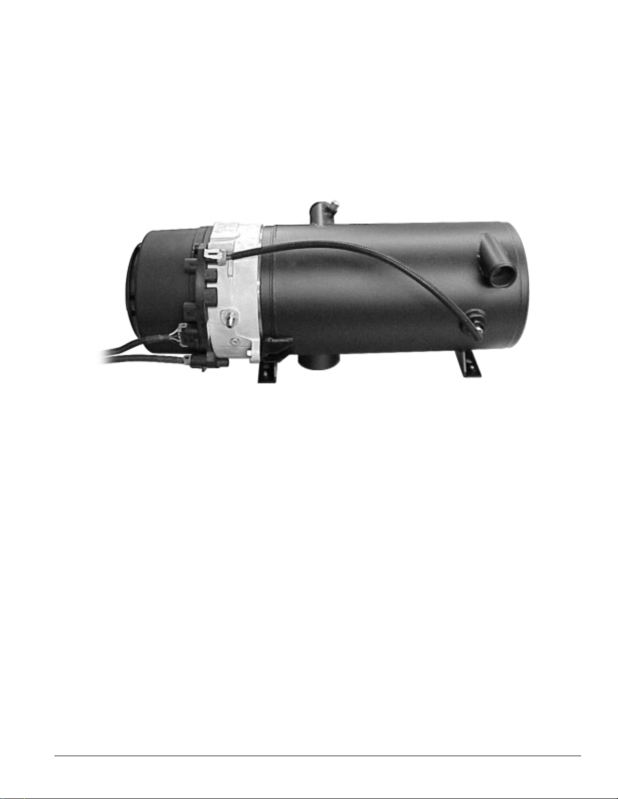
INTRODUCTION
MODEL: M50/M80/M105
This manual is provided to assist in troubleshooting
and maintaining the PROHEAT M-Series heater. They
are designed for use on any diesel-equipped vehicle
including trucks, buses (school, transit and coach),
construction equipment, off road equipment,
military equipment and cargo.
PROHEAT heaters are used for the following applications:
(1) Engine Block Heat – A PROHEAT will preheat an
engine block to ensure reliable starting in cold
weather. Its’ use throughout the year will reduce
engine wear caused by cold starts.
(2) Supplemental Heat (engine running) – The PROHEAT
can be used while the vehicle is operating to
provide supplemental heat for the engine and/or
passenger compartment.
(3) Cargo Heat – The PROHEAT can supply heat to
individual compartments as a stand-alone heating
system, or it can provide supplemental heat to an
existing heating system.
(4) Marine – Marine applications typically involve the
engineering and installation of a complete
hot-water heating system of which PROHEAT is only
one component. Teleflex recommends that only an
expert in marine hot-water heating systems install
a PROHEAT for marine applications.
NOTE: It is the installer’s responsibility to ensure that
an installation complies with all applicable codes and
regulations.
B.

PROHEAT M-SERIES SERVICE MANUAL
B-2
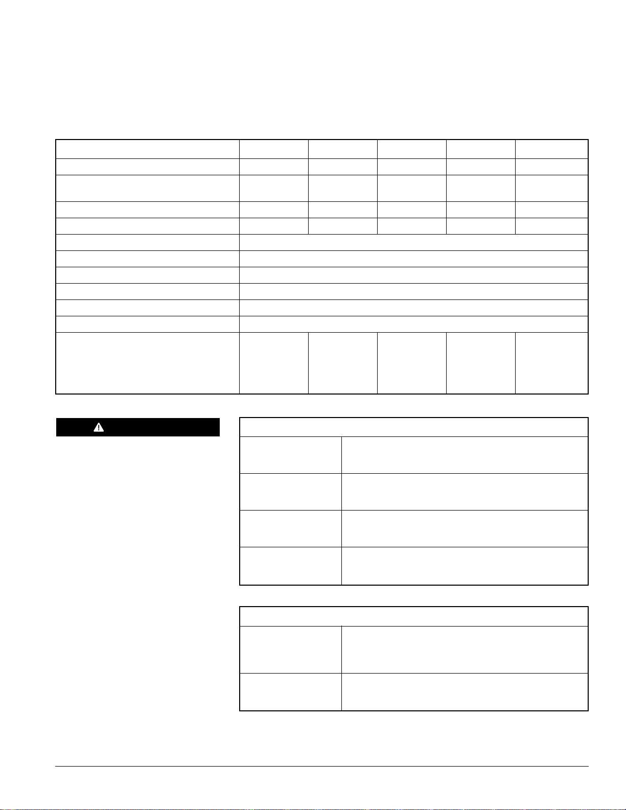
M50 12V M50 24V M80 12V M80 24V M105 24V
HEAT OUTPUT ± 10% BTU/hr (kW) 50,000 (15) 50,000 (15) 80,000 (23) 80,000 (23) 105,000 (30)
SYSTEM VOLTAGE
Nominal Voltage (Range) 12 (10 – 15) 24 (20 – 30) 12 (10 – 15) 24 (20 – 30) 24 (20 – 30)
CURRENT DRAW Amps 9.5 4.5 8.5 4.0 7.5
FUEL CONSUMPTION US gph (lph) 0.48 (1.8) 0.48 (1.8) 0.78 (2.95) 0.78 (2.95) 1.04 (3.6)
IGNITION TYPE Electronic Spark Ignition
FUEL TYPES Diesel, JP8, Jet A1, Arctic
COOLANT OUTPUT TEMPERATURE MAX. 185°F (85°C)
AMBIENT OPERATING TEMPERATURE -40°F to +122°F (-40°C to +50°C)
WEIGHT lbs (kg) 53 (23.5)
HEAT EXCHANGER CAPACITY US gal (l) 0.5 (2)
COOLANT SYSTEM
Minimum Capacity US gal (l) 2.64 (10) 2.64 (10) 2.64 (10) 2.64 (10) 2.64 (10)
Recommended Flow Rate Through
Heater US gpm (lpm) 5 (19) 5 (19) 7 (26.5) 7 (26.5) 9 (34)
PROHEAT M-SERIES SERVICE MANUAL 1-1
TECHNICAL
SPECIFICATIONS
1.0
SYSTEM OUTPUTS
AUXILIARY OUTPUT Same as System Voltage
Maximum 1 Amp draw (over-load shut-off protection)
High-side switched
SWITCH/TIMER Same as System Voltage
POWER Maximum 1 Amp draw (over-load shut-off protection)
High-side switched
COOLANT PUMP Same as System Voltage
Maximum 10 Amp draw (over-load shut-off protection)
High-side switched
INDICATOR LIGHT Same as System Voltage
Maximum 1 Amp draw (over-load shut-off protection)
High-side switched
SYSTEM INPUTS
SWITCH 10 – 30V
Standard Run Mode
Preheat Run Mode
Supplemental Run Mode
COOLANT PUMP 10 – 30V
AUXILIARY Allows independent operation of Coolant Pump through
the Proheat Control Module
DANGER
Do not use gasoline.

PROHEAT M-SERIES SERVICE MANUAL
1-2
4X M8X1.25
MOUNTING PEM NUTS
6X
Ø.41 (10)
Ø2.75 (70)
1.40 (36)
2.13 (54)
3.94
(100)
8.20 (208)
4.93
(125)
9.53 (242)
.75 (19)
8.61
(219) 5.37
(136)
7.63
(194)
9.00 (229)
1.97 (50)
9.55 (243)
2X
1.50 (38)
12.60 (320)
3.23
(82)
5.90
(150)
4.33
(110)
23.30 (592)
4.45
(113)
5.77
(147) -4 JIC MALE FUEL INLET
(INTERNAL FUEL FILTER)
SERVICE SPACE
REQUIREMENT
(SEE NOTE 3)
BOTTOM VIEW
TOP VIEW
SIDE VIEW
FRONT VIEW
REAR VIEW
INLET
OUTLET
THE INLET AND OUTLET CAN
BE REVERSED WITH THE
ADDITION OF A SECONDARY
TEMPERATURE SENSOR
EXHAUST (SEE NOTE 4)
PCM
1. DIMENSIONS ARE IN INCHES (MILLIMETERS IN BRACKETS).
2. TYPICAL EXHAUST CUTOUT 3.25" CENTERED ON EXHAUST.
3. SERVICE SPACE REQUIRED TO REMOVE BURNER HEAD AND COMBUSTION TUBE FOR PERIODIC
INSPECTION AND CLEANING.
4. THE EXHAUST PIPE SHOULD HAVE A MINIMUM DIAMETER OF 2.75", A MAXIMUM LENGTH OF 5'
AND HAVE NO MORE THAN 180 DEGREES OF BENDS.
NOTES:
PHYSICAL1.1

PROHEAT M-SERIES SERVICE MANUAL 1-3
ELECTRICAL1.2
PR
O
HEAT P
CM
P2 - CONTROL
(
SWITCH
)
METRI-PACK 150 SERIES, 8 PI
N
N
O
TE
1
INDICATOR OUTPUT
(
HIGH SIDE SWITCHED. DASH OR PROHEAT TOGGLE SWITCH LIGHT
)
(
1 AMP MAX
)
()()
POWER OUTPUT
(
CONSTANT POWER. TIMER/SWITCH REMOTE PANEL
)
(
1 AMP MAX SHARED WITH P3-D
)
()()
MAIN SWITCH INPUT
(
STANDARD "ON" SIGNAL OR PREHEAT UNLATCH
)
(
ACTIVE HIGH 10 TO 30 VOLTS
)
()()
B
B
GROUND
(
INDICATOR GROUND
)
(
1 AMP MAX
)
()()
R
S
232 R
x
R
S
232 T
x
FACTORY USE
(
N/A
)
()
GROUND
(
1 AMP MAX
)
()
COO
LANT P
U
MP
G
R
OU
N
D
COO
LANT P
U
MP
OU
TP
UT
INDICATOR OUTPUT
(
1 AMP MAX
)
()
ACCESSORY POWER OUTPUT
(
1 AMP MAX SHARED WITH P2-C
)
()
GROUND
(
ACCESSORY OUTPUT GROUND
)
(
1 AMP MAX
)
()()
PREHEAT SWITCH INPUT
(
ACTIVE HIGH 10 TO 30 VOLTS
)
()
SUPPLEMENTAL SWITCH INPUT
(
ACTIVE HIGH 10 TO 30 VOLTS
)
()
PUMP
(
COOLANT
)
SWITCH INPUT
(
ACTIVE HIGH 10 TO 30 VOLTS
)
() ( )
P4
P
U
M
P
(
COOLANT
)
PR
O
HEAT P
CM
B
A
B
A
P
3
DATALINK
(
DOWNLOAD
)
F
F
C
D
E
B
A
C
D
E
B
A
P2
CO
NTR
OL
(
SWITCH
)
H
H
F
D
F
D
O
.E.M.
SU
PPLIE
D
BATTERY POSITIVE
(
FUSE/BREAKER 30 AMP
)
()
BATTERY NEGATIVE
(
GROUND
)
()
P1
P
O
WE
R
A
A
B
A
B
A
PR
O
HEAT P
CM
P1 - P
O
WE
R
METRI-PACK 280 SERIES, 2 PI
N
N
O
TE
2
RE
CO
MMENDED
25 AMP F
USE
P3 - DATALINK
(
DOWNLOAD
)
METRI-PACK 150 SERIES, 6 PI
N
N
O
TE
1
N
O
TE
3
P5 - AUX
(
OUTPUT
)
METRI-PACK 150 SERIES, 2 PI
N
N
O
TE
1
N
O
TE
3
O
.E.M.
SU
PPLIE
D
P4 - PUMP
(
COOLANT
)
METRI-PACK 150 SERIES, 2 PI
N
N
O
TE
1
N
O
TE
3
VEHI
C
LE
G
R
OU
N
D
(
-
)
P
O
WER
SU
PPL
Y
(
+
)
()
P8 - T1: TEMP
S
EN
SOR
P7 - T2: TEMP
S
EN
SOR
N
O
TE
3
P6 - F
U
T
U
RE
USE
N
O
TE
3
MAXIM
U
M 10 AMP
S
1
53000
1
4
12
066304
12
05
2
634
L
OCK
PART#
P1-P
O
WE
R
P2-CONTROL
(
SWITCH
)
P3-DATALINK
(
DOWNLOAD
)
P4-PUMP
(
COOLANT
)
P
CM
CO
NNE
C
T
OR
12
05
2
6
4
1
1
53000
2
7
CO
NNE
C
T
OR
PART#
12
0
47
937
C
AVITY
S
EA
L
PART#
12
059
1
68
12
0
4
80
7
4
12
0
4
8086
12
0
4
8086
12
0
4
80
7
4
12
059
1
68
12
0
1
5
1
93
WIRE
S
EA
L
PART#
12
0
4
8086
12
0
7741
3
TERMINAL
PART#
12
0
4
80
7
4
----
12
059
1
68
N
O
TE
S:
1
/
150
S
ERIE
S
CO
NNE
C
T
O
R A
SS
EMBLIE
S
T
O
BE
US
ED WITH 18AW
G
WIRE WITH MAXIM
U
M .1" IN
SU
LATI
O
N DIAMETER. WIRE M
US
T MEET
O
R EX
C
EED
S
AE
J
1128
G
PT
S
PE
C
IFI
C
ATI
O
N
S.
2
/
280
S
ERIE
S
CO
NNE
C
T
O
R A
SS
EMBLIE
S
T
O
BE
US
ED WITH 10AW
G
WIRE WITH MAXIM
U
M .161" IN
SU
LATI
O
N DIAMETER. WIRE M
US
T MEET
O
R EX
C
EED
S
AE
J
1128
G
PT
O
R
G
XL
.
3
/
ALL
U
N
US
ED
CO
NNE
C
TI
O
N
S
O
N THE P
C
M ARE
SU
PPLIED WITH
S
EAL PL
UGS
O
N
S
TANDARD HEATER
S.

PROHEAT M-SERIES SERVICE MANUAL
1-4

PROHEAT M-SERIES SERVICE MANUAL 2-1
PRINCIPLE OF
OPERATION
COMPONENT DESCRIPTIONS
Impeller-style blower driven by the Motor provides the principle combustion air.
Drives the Combustion Air Blower, Air Compressor and Fuel Supply Pump.
A positive displacement, gear-type pump that draws fuel from the vehicle fuel
tank and supplies it to the Fuel Regulator. Pressure is regulated between
7 – 10 PSI by means of an internal relief valve. Fuel is re-circulated within the
pump, therefore a fuel return line to the tank is not required.
Diaphragm-type pressure reducing valve. The Fuel Regulator drops the fuel
supply pressure to atmospheric pressure (0 PSI).
Air-aspirating type burner nozzle. Compressed air flows through the air
passages, exiting the nozzle in front of the fuel orifice creating a vacuum in
the fuel supply. This draws fuel from the Fuel Regulator and the combined
fuel/air mixture is atomized into the combustion chamber.
Electrically operated solenoid valve which controls fuel flow to the Fuel Nozzle.
Rotary vane compressor that supplies air pressure (in the range of 3 – 5 PSI)
to the Fuel Nozzle.
Electronic Ignition Module with plug-in electrode.
Electronic control module monitors the PROHEAT sensors, operating conditions,
and controls the Motor and other devices. Diagnostics are utilized for both
safety in operations and detection of component faults to aid in service and
troubleshooting. The PCM contains the flame sensor which senses the flame
intensity. This information can be retrieved by a personal computer using
PROHEAT Datalink software.
Directs the air supplied by the blower through a swirler into the combustion
zone, mixing it with the atomized fuel/air mixture from the Fuel Nozzle.
2.0
2.1
Combustion Air Blower:
Motor:
Fuel Supply Pump:
Ignition Module:
PCM:
(PROHEAT Control Module)
Fuel Regulator:
Air Compressor:
Fuel Shut-off Valve:
Fuel Nozzle:
Combustion Tube:

PROHEAT M-SERIES SERVICE MANUAL
2-2
Coolant is circulated through the heat exchanger via the inlet and outlet
ports. Heat is transferred from the heat exchanger through the inner wall of
the exchanger into the coolant. The exhaust gases are directed out through
the exhaust port.
Measures the coolant temperature near the outlet port of the heat exchanger
and sends this information to the PCM. It must be connected at all times
for overheat protection.
For installations where the coolant flow through the heat exchanger is
opposite of what is specified on page 1-2. This sensor also measures the
inner heat exchanger surface temperature for an overheat condition.
Circulates coolant through the PROHEAT and vehicle heating system.
Depending on the PROHEAT installation, it may be operated by the PCM.
Heat Exchanger:
Coolant Pump:
Temperature Sensor 1:
Temperature Sensor 2:
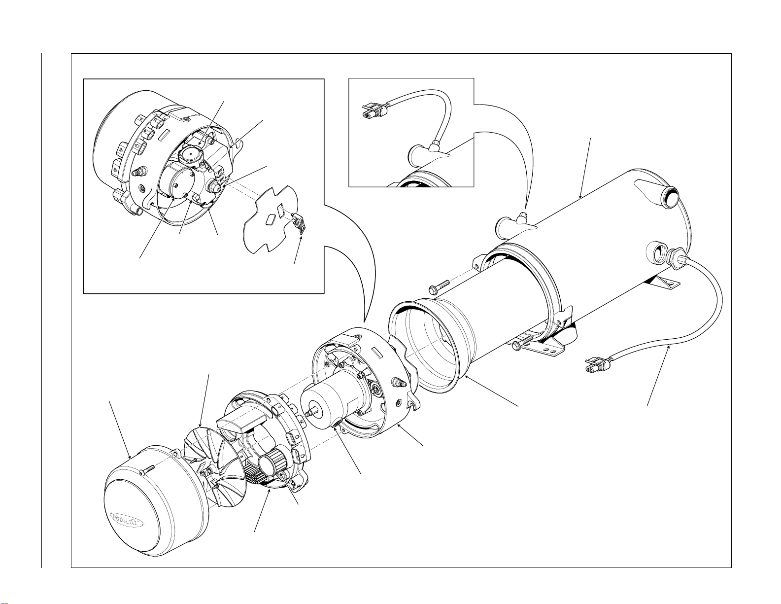
PROHEAT M-SERIES SERVICE MANUAL 2-3
BLOWER HOUSING
FUEL
SUPPLY
PUMP
FUEL REGULATOR
FUEL
NOZZLE
FUEL
SHUT-OFF
VALVE
AIR COMPRESSOR
IGNITION MODULE
PCM (PROHEAT CONTROL MODULE)
COMBUSTION TUBE
HEAT EXCHANGER
TEMPERATURE SENSOR 1
TEMPERATURE
SENSOR 2
(IF EQUIPPED)
COMBUSTION AIR BLOWER
MOTOR
BURNER HEAD FLANGE
AIR FILTER
IGNITION
ELECTRODES

PROHEAT M-SERIES SERVICE MANUAL
2-4
NORMAL OPERATING
SEQUENCE
1.. . . . . . . . . . . . . . . Switch On:
6. . . . . . . . . . . . . . . Cool Down:
5. . . . . . . . . . . . . . . Full Output:
3. . . . . . . . . . . . . . . . . . Ignition:
2. . . . . . . . . . . . . . . . Pre-check:
7.. . . . . . . . . . . . . . . . . Standby:
8.. . . . . . . . . . . . . . . Switch Off:
2.2
If the coolant temperature is below 160°F (71°C) the PROHEAT enters
Pre-check. If the coolant temperature is above 160°F (71°C) the PROHEAT
enters Standby.
The PCM performs self diagnosis checking sensors for correct range and
electrical components for over-load. Also during the first Pre-check, the Ignition
Module is powered for five seconds to allow a service technician to visually
check for a spark.
The Motor and Coolant Pump start first, followed by the ignition spark, and
Fuel Shut-off Valve. The Ignition Module sparks for 30 seconds during which
time the flame sensor must detect correct combustion.
At the end of the Ignition cycle the Flame Sensor checks the combustion. If
acceptable, the PROHEAT enters Full Output. If not acceptable, the PROHEAT
goes to Cool Down and then will start again at Pre-check. If the second start
cycle fails the PROHEAT will enter Fault Shut Down.
The PROHEAT will continue in Full Output until the coolant temperature
reaches 185°F (85°C) at the PROHEAT outlet Temperature Sensor.
The Motor and Coolant Pump continue to operate for up to three minutes, the
Motor stops and the PROHEAT enters Standby. The PROHEAT will Cool Down
for three reasons:
• Coolant reaches 185°F (85°C).
• A fault is detected. Go to Troubleshooting and Repair
• The PROHEAT is operating in Ignition or Full Output when it is switched off.
The Coolant Pump continues to circulate coolant throughout the system (go
to Auxiliary Input Section for alternative operating modes). When the coolant
temperature drops to its cycle on temperature, the PCM will repeat the cycle
starting at Pre-check.
If the PROHEAT is in Ignition or Full Output, it will Cool Down first, then shut OFF.
If the PROHEAT is in Standby, it will shut OFF immediately.
If the PROHEAT diagnostics sense a system or component fault, the PROHEAT will
shut down all components and flash a fault code(s) which best represents the
conditions. To reset the PROHEAT, it must be switched off and then on again.
NOTE: Damage may occur it the fault codes are ignored and the PROHEAT is
repeatedly switched off and on without addressing the problem.
4. . . . . . . . Combustion Check:
9. . . . . . . . . . Fault Shut Down:

PROHEAT M-SERIES SERVICE MANUAL 3-1
TROUBLESHOOTING
AND REPAIR
3.0
Problems with the PROHEAT and its operation will be indicated in two ways:
1. PROHEAT Diagnostic Faults indicated by means of a flashing diagnostic
code on an indicator light (if equipped). Go to page 3-2.
2.
Operational problems may not be identified with a flashing diagnostic code
(e.g., blown fuse, obstructed coolant flow, air leaks in fuel supply line)
.
Go to page 3-40
.
Troubleshooting a Problem
Locate the PROHEAT, remove the enclosure lid if used and visually check for
any problems with wiring harnesses, fuel leaks, coolant leaks, exhaust pipe
damage and environmental condition.
If equipped with a diagnostic indicator light, and it is flashing, determine the
code based on page 3-2.
If no code is indicated, turn the PROHEAT off and then on again using the
existing operational switches, timer or a PROHEAT remote start switch
(PROHEAT P/N PK0091).
Let the PROHEAT attempt to start and/or operate. Observe the operation.
NOTE: The PROHEAT will always attempt to start twice, as long as the
coolant temperature is below 160°F (71°C). If a fault is detected it will shut
down, go through a Cool Down and attempt a second start. After both
attempts to start or operate, an indicator light will flash a diagnostic code.
Go to page 3-2.
• If the indicator light flashes, count the number of flashes and refer to
the troubleshooting diagnostic code description for that number on the
following pages.
•If the PROHEAT runs but is not performing or operating correctly, consult
the Operational Problems section, page 3-40.
Troubleshooting and Repair Tools Required
•Remote Start Switch (PROHEAT P/N PK0091)
Allows the service technician to work at the PROHEAT. Isolates the
PROHEAT from the existing vehicle system controls and comes with a
built-in indicator light.
•Temperature Sensor (PROHEAT P/N 200301K)
Allows the service technician to start a PROHEAT when the coolant
temperature is greater than 160°F (71°C). To be used only for
troubleshooting.
STEP 1
STEP 2
STEP 3
STEP 4

PROHEAT M-SERIES SERVICE MANUAL
3-2
3.1 SYSTEM AND COMPONENT
DIAGNOSTICS
The PCM continually monitors the PROHEAT operating conditions. If the PCM
detects a problem, the indicator light flashes a diagnostic code(s).
The diagnostic indicator light may be located:
• In the toggle of the ON/OFF Switch provided by PROHEAT (standard
installation kit).
• In the PROHEAT Timer manual ON light (red).
• In an OEM indicator light package.
• In the remote switch (PROHEAT P/N PK0091) used for troubleshooting.
NO. OF FLASHES DIAGNOSTIC CODE DESCRIPTION PAGE
1Start 3-3
2Flame Out 3-24
3Coolant Flow 3-25
4Overheat 3-27
5Voltage 3-27
6Flame Fault 3-29
7Temperature Sensor T1 3-29
8Fuel Shut-off Valve 3-31
9Temperature Sensor T2 3-32
10 Ignition Module 3-32
11 Coolant Pump 3-33
12 Motor 3-34
13 Auxiliary Output 3-35
14 Switch Output 3-36
SYSTEM
DIAGNOSTICS
COMPONENT
DIAGNOSTICS

PROHEAT M-SERIES SERVICE MANUAL 3-3
START Diagnostic Code
Indicates that the PCM Flame Sensor did not detect a flame or the flame was
too weak to be detected during the FULL ignition period (M50/M80/M105 –
30 second ignition period).
Troubleshoot the Start diagnostic code based on the following symptoms:
1. Fuel System. Go to page 3-4 to 3-15, Steps 1 through 7.
a) There is no fuel, fuel odor or atomized fuel coming from the exhaust pipe.
b) There is no hot exhaust coming from the exhaust pipe.
2. Ignition System. Go to page 3-18.
a) There is raw fuel and/or atomized fuel and a raw fuel odor coming
from the exhaust pipe.
b) There is no hot exhaust coming from the exhaust pipe.
3. PCM (PROHEAT Control Module) Flame Sensor circuit. Go to page 3-20.
a) There is a flame and the combustion sounds good, the PROHEAT
appears to be operating normally.
b) No smoke, raw fuel odor or atomized fuel is coming from the
exhaust pipe.
4. Motor and/or PCM fault. Go to page 3-22.
a) The Motor is NOT running. Ignition and Coolant Pump are operating.
b) No smoke, raw fuel odor or atomized fuel coming from the exhaust pipe.
3.1.1
(1 Flash)

PROHEAT M-SERIES SERVICE MANUAL
3-4
Fuel and fuel supply – Check:
a) Vehicle fuel level and/or for fuel gelling during cold weather.
b) Air leaks and/or restrictions in the fuel supply lines to the PROHEAT.
c) The PROHEAT operation when supplying fuel from a direct source.
Test Procedure – Supplying fuel from a remote source:
a) Remove the fuel supply line from the PROHEAT fuel inlet.
b) Using a length of fuel line connected from the PROHEAT fuel inlet to a
direct source of CLEAN fuel. Switch the PROHEAT on and operate for at
least one complete cycle. Observe the operation.
If the PROHEAT functions correctly, the fault is in the vehicle fuel system.
Check fuel lines, connections and routing back to fuel tank. Consult OEM
for service requirements.
If a Start diagnostic code is indicated, the problem is in the PROHEAT
fuel system. Proceed to Step 2.
START: Fuel System Step 1
(1 Flash)
Figure 3-1: Remote Fuel Supply
FUEL
CONTAINER
FUEL INLET
NOTICE
When fuel system is open, the
PROHEAT will smoke and stumble
until the air is purged from the
system. It may be required to cycle
more than one time.
WARNING
Flammable.
This manual suits for next models
2
Table of contents
Other Proheat Heater manuals


