Proheat X30 User guide

OWNER’S HANDBOOK

X30 Owner’s Handbook Page 1
Safety ................................................................................................................................. 2
Introduction ....................................................................................................................... 4
Operating your PROHEAT ................................................................................................... 5
Optional Sleeper Fan Operation ......................................................................................... 7
Toggle Switch – Timer – PFC ........................................................................................... 8
Timer Instructions .............................................................................................................. 9
PFC Instructions .............................................................................................................. 10
Caring for your PROHEAT ................................................................................................ 11
Troubleshooting ............................................................................................................... 17
Troubleshooting – Operation Indicators/Diagnostic Codes ............................................. 18
Troubleshooting – Function Diagnostics ......................................................................... 22
Warranty .......................................................................................................................... 25
Owner’s responsibility ...................................................................................................... 26
Contents

Page 2 X30 Owner’s Handbook
ELECTRICAL – Electric shock can cause severe personal injury, burns, and death. Before working
on any unit, disconnect the batteries. Use only approved materials and methods when working on the
electrical system and follow local electrical codes. Never work with electricity in wet conditions or
when you are feeling fatigued.
WARNING
POISONS/TOXINS – Fuel and coolant are toxic and in some cases, carcinogenic. Wear eye and hand
protection at all times. Remove contaminated clothing immediately and wash contaminated skin. Do not
breathe in vapors.
WARNING
MOVING/HOT PARTS – Moving/hot parts can cause severe injury and or death. Before working on
any unit, shut it off. Do not operate any unit until protective covers have been replaced. Always ensure
bolts and clamps are correctly torqued and secured. Inspect mechanical components periodically for
damage and corrosion.
WARNING
CALIFORNIA PROPOSITION 65 WARNING – Do not operate heater in garages or in other closed
or unventilated areas. Diesel exhaust and some of its constituents are known to the State of California
to cause cancer, birth defects, and other reproductive harm.
Electrical components in this product may contain lead, a chemical known to the State of California to
cause cancer and birth defects and other reproductive harm.
DANGER
COOLANT – Never remove the filler cap when the engine is hot – escaping steam or scalding water
could cause serious personal injury. The coolant level in the expansion tank should be checked at least
weekly (more frequently in high mileage or arduous conditions). Always check the level when the system
is cold. Unscrew the filler cap slowly, allowing the pressure to escape before removing completely.
Never run the engine without coolant.
Prevent anti-freeze coming in contact with the skin or eyes. If this occurs, rinse immediately with plenty
of water. Anti-freeze will damage painted surfaces.
Never top-up with salt water. Even when travelling in territories where the water supply contains salt,
always ensure you carry a supply of fresh (rain or distilled) water.
WARNING
Safety

X30 Owner’s Handbook Page 3
Throughout this manual, you will see notes labeled DANGER, WARNING, CAUTION and NOTICE
to alert you to special instructions or precautions concerning a particular procedure that would be
hazardous if performed incorrectly or carelessly.
Observe them carefully!
These safety alerts alone cannot eliminate all hazards. Strict compliance with these special
instructions and common sense are major accident prevention measures.
Safety
Information that is important to
proper installation or maintenance,
but is not hazard-related.
Notice
Immediate hazards that
will result in severe injury
or death.
DANGER
Hazards or unsafe practices
that could result in severe
personal injury or death.
WARNING
EXHAUST – Inhalation of exhaust gas (containing carbon monoxide) may cause severe personal injury
and/or death. Anyone suspected of suffering from CO inhalation should be removed from the
hazardous area and given medical assistance immediately.
WARNING
FUEL – Exercise extreme caution when working near fuel or fuel-filled equipment. Do not operate
heater during fueling operations. In addition, do not smoke or handle open flame equipment, such as
a blowtorch, around fuel.
WARNING
EXPLOSION HAZARD – Do not operate heater where combustible fumes or airborne particles, such
as sawdust, are present.
WARNING
Hazards or unsafe practices
that could result in minor
injury or product or
property damage.
CAUTION
Safety Considerations
FIRE HAZARD – Do not place any flammable items around the heater and exhaust pipe.
WARNING
BATTERIES – Wear hand and eye protection when working near batteries. Do not smoke or use
open flames near batteries.
WARNING

Page 4 X30 Owner’s Handbook
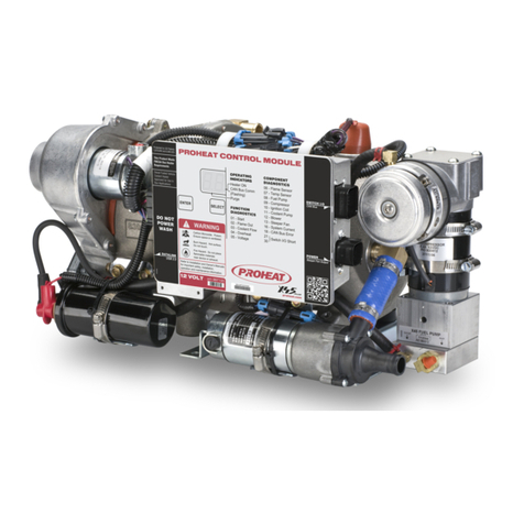
Congratulations on your purchase of a PROHEAT X30 diesel-fired heater. This handbook is provided to
summarize the operation and maintenance of the PROHEAT X30 for the Owner/Operator.
For complete information, please refer to the Installation and Service manual SL9211 at www.proheat.com
Although trucks have been used throughout this book, applications for PROHEAT are by no means
limited to trucks. PROHEAT heaters are designed to be used on any diesel equipped vehicle
including: trucks, buses (school, transit and coach), construction equipment, off road equipment,
military equipment and cargo.
PROHEAT heaters are used in the following applications:
• Preheats an engine block to ensure reliable cold weather starting.
It is recommended that PROHEAT is used year round (winter and summer) to reduce engine
wear associated with cold starting.
• With the engine off—supplies heat to the engine and sleeper for comfort and reduced idle time
resulting in cost savings through reduced fuel consumption and engine wear.
• With the engine running—adds heat to the coolant system when the engine does not provide
adequate reject heat for the vehicles interior.
• Provides heat to protect cargo from cold weather damage.
• With the engine off - supplies minimal heat to prevent freezing over long periods of time.
Introduction
Notice
eNgiNe Block heat
eNgiNe & Sleeper heat
SupplemeNtal heat
cargo heat
aNti-Freeze heat

X30 Owner’s Handbook Page 5
Your PROHEAT X30 is controlled by either an ON/OFF manual toggle switch or by an optional
PROHEAT 7-day timer. The timer can be controlled manually, or it can be set to start at a predetermined
time. Both devices have a light that indicates when the heater is operational as well as flashing to indicate an
error state
. Your installer may have enabled optional features and heating modes.
Please see the X30
Installation and Service manual SL9211 at www.proheat.com or your Dealer for more information.
1. SWITCH ON – The ON/OFF switch (or Timer) lamp and the Proheat Control Module (PCM) “ON”
LED will light. In addition, the Hour Meter (Auxiliary Output) will be powered. If the coolant
temperature is below 150°F (65°C) the PROHEAT enters Pre-check. If the coolant temperature is
above 150°F (65°C) the PROHEAT enters Standby.
2. PRECHECK – The PCM performs a short diagnostic cycle. This takes a few seconds to check
components for proper ranges, short-circuits and open circuits. If there are no errors indicated,
the PROHEAT goes to “Ignition”.
3. IGNITION –
The blower starts first, followed by the coolant pump, ignition spark, air compressor
and
fuel pump. The ignition electrode sparks for up to 60 seconds. Once a good flame is detected, the
PROHEAT goes to “Full Output”.
4. FULL OUTPUT – The PROHEAT runs at Full BTU Output until the coolant temperature reaches
185°F (85°C) at the heater outlet. If the time to heat the coolant to 185°F (85°C) is longer than
10 minutes the PROHEAT then shuts the flame off and goes to “Cool Down” (Purge). If the time to
heat the coolant to 185°F (85°C) is shorter than 10 minutes the heater will slow down and reduce
the heat output for the remainder of the 10 minutes.
5. MODULATING BTU OUTPUT – The PROHEAT may reduce the heat output up to 50% automatically
once the coolant temperature reaches 185°F (85°C) at the heater outlet.
Operating your PROHEAT
StaNdard mode
operatiNg SequeNce

Page 6 X30 Owner’s Handbook
The heating cycle will end once the 10 minutes have past OR the coolant temperature reaches
194°F (90°C) at the heaters outlet.
The PROHEAT then shuts the flame off and goes to “Cool down” (Purge).
6. COOL DOWN (Purge) – The air compressor and fuel pump shut off immediately. The blower
and coolant pump continue to run. After 3 minutes, the blower stops and the PROHEAT goes
to “Standby.”
7. STANDBY – The coolant pump circulates the coolant through the system until the temperature
drops to 150˚F (65˚C) at the heater outlet; then it will enter Precheck and repeat steps 2 to 6. The
PROHEAT will continue to repeat steps 2 to 5 until it is switched “off.”
8. SWITCH OFF – If PROHEAT is in Full Output, it will Cool Down (Purge) first, then shut “OFF”.
If PROHEAT is in Standby, it will shut “OFF” immediately.
When switched OFF, the Sleeper Fan (if equipped) output turns off.
When switched OFF, the Hour Meter (Auxiliary Output) will shut off.
Operating your PROHEAT

X30 Owner’s Handbook Page 7
Optional Sleeper Fan Operation
Today’s sleepers are designed for maximum comfort for the vehicle operator. Generally the units are
larger and have accessories that compete for battery power with auxiliary heaters. PROHEAT is a
cost-saving component by reducing fuel consumption and engine maintenance. Therefore, it should
be given priority over these accessories.
PROHEAT installation recommendations are designed to allow the operator to:
• Run the PROHEAT with the vehicle ignition key in the OFF position
• Set the desired sleeper ambient temperature using the dedicated Proheat thermostat
The vehicle operator’s responsibility is to ensure that:
• Coolant valves used in the heating system are open: These can be manually or electrically
operated (electrically operated valves must be opened before shutting the vehicle OFF)
• When operating the PROHEAT, power consuming accessories such as refrigerators, DVD’s, TV’s,
satellite receivers, heated mirrors, etc. are not used to ensure enough starting current for the engine
• Sleeper curtains are closed: The PROHEAT is designed to heat the sleeper and engine as efficiently
as possible – heating the cab, fuel tanks and batteries means longer run time which will require
more battery power
Notice
For more information on Sleeper Fan installation,
please refer to the Installation and Service manual
SL9211 at www.proheat.com

Page 8 X30 Owner’s Handbook
Up Arrow
Manual Mode
Solid Red Led = Heater Active
Flashing Red Led = Heater Fault
Timer Mode
Solid Green Led = Timer Active
Back Soft Key
Back (Default) Or No
Down Arrow
Select Soft Key
Select (Default), Set,
On, Off, Edit Or Yes
11:52AM
MON106F
STANDARD
M00:59T1 T2 T3
Toggle Switch – Timer – PFC
T-II Manual
Indicator Light
(Red)
Timer
Indicator Light
(Green)
timer
proheat FuNctioN coNtroller (pFc)
toggle Switch

X30 Owner’s Handbook Page 9
T-II
Timer Instructions
MANUAL button is used to turn the PROHEAT
On and Off when desired.
STEP 1 Press “MANUAL” to turn on the
PROHEAT (red light will go on and
the heater will operate indefinitely).
STEP 2 Press “MANUAL” again to turn Off
the heater (red light and the
PROHEAT will turn Off).
STEP 1 Press and Hold “TIMER” (green light
will turn on and “T1” will flash).
STEP 2 Press “ ” or “ ” to set time
STEP 3 Press “DAY” to advance the day.
STEP 4 Release “TIMER”. (green light and
“T1” will remain lit to activate timer).
STEP 1 Press and hold “CLOCK”
STEP 2 Press “ ” or “ ” to set time
STEP 3 Press “DAY” to advance the day.
STEP 4 Release “CLOCK”.
For complete Timer information, please refer
to the T-II Timer Installation and Operating
Instructions 958829 at www.proheat.com
Notice
maNual operatioN timed operatioN
SettiNg clock

Page 10 X30 Owner’s Handbook
PFC Instructions
11:52AM
STANDARD
M
00:59
T1 T2 T3
MON106F
00:59T1 T2 T3
The “”button is used to turn the heater on and
off when desired regardless of set Timers.
Press “”to activate the heater. The Red
Manual Button LED will turn on and the heater
will operate indefinitely (factory preset).
If the Manual Mode Runtime has been set you
will see the remaining time left before the heater
automatically turns off.
When the heater has an active Flame the icon will
change to a black background. Pressing “”
button again will de-activate the heater. (The Red
LED will go out and the heater will turn off.)
When a Timer Mode is enabled you may see a
number of different screens depending on how
the Timer was programed (see Timer settings).
Press the “”button repeatedly to toggle
through and activate T1, T2, T3 or Group Timers.
(Green Timer LED will turn on).
The Heater will switch on at the set program(s)
time, run for the set duration, then switch off
automatically.
If the heater has been turned on by a timer event,
Pressing “”button will turn the heater off but
leaves the timer(s) schedule active.
Pressing the
“ ”
Button repeatedly to toggle
through
and deactivate the current set timer
program(s) (Green Timer LED will go out and
screen will not show T1,T2,T3.
If a password has been set it may not be possible
to deactivate the scheduled timer(s).
For complete PFC information, please refer
to the PFC Installation and Operating
Instructions 949900 at www.proheat.com
Notice
“Manual” and “Timer” cannot be active at the
same time. If “”is active and the “ ” button
is pressed, the heater will turn off and the Red
Manual Button LED will go out.
Notice
maNual operatioN timed operatioN

X30 Owner’s Handbook Page 11
Caring for your PROHEAT
Your PROHEAT has been designed to operate with a minimum of maintenance. Always return to your
authorized PROHEAT dealer for major service. Your PROHEAT dealer has the specialized equipment
necessary to keep your PROHEAT running safely and reliably.
For more maintenance information, refer to the Installation and Service manual SL9211
at www.proheat.com
Operate the PROHEAT year round (winter & summer). Use the PROHEAT to preheat the
engine before starting. Savings will result from reduced engine idle time and maintenance.
This also keeps the PROHEAT components and fuel system in good running order.
PROHEAT weekley maintenance:
Visually inspect the Proheat, mounting brackets, fuel line, harnesses, coolant lines and
exhaust system for damage, loose parts and leakage.
Run the Proheat a minimum of once a week to keep new fuel in the heater’s critical components.
PROHEAT annual maintenance:
A higher duty cycle may require a more frequent
maintenance schedule.
Proper maintenance will result in the following benefits:
• Maximum heat transfer to the coolant
• Minimum battery power draw
• Long term cost savings
• Increased reliability
Notice
Notice
Check Combustion
Air Inlet for restrictions.
Clean as required.

Page 12 X30 Owner’s Handbook
check exhauSt SyStem • Make sure the exhaust pipe is fully installed,
vents outside of the engine compartment and
is clear of the underside of the vehicle.
• Check the pipe for dents, restrictions or severely
corroded areas and replace if necessary.
• Ensure exhaust pipe clamps are tight.
Caring for your PROHEAT
cleaN heater eNcloSure • Remove the heater enclosure cover.
• Clean any accumulated debris or dust from
the components.
• Blow out the compartment with compressed air.
• Do not pressure wash.
• Make sure the opening around the exhaust
pipe is clear.
• Visually inspect all the components for wear
or damage.
check Fuel Filter • Remove and inspect fuel filter.
Clean or replace as necessary.
Apply Diesel
to O-Rings
Fuel Filter
Torque to
150±10 In/Lbs
(17±1.1 Nm)

X30 Owner’s Handbook Page 13
check BatterieS • Check the condition of batteries and the power connections.
The heater will not function properly with weak batteries or
corroded connections.
• Note For best results load test each battery individually.
Caring for your PROHEAT
check Fuel SyStem • Check fuel pick-up tube, clamps and line to the heater for damage, cracks from aging or leakage.
• Check fuel pump and fittings for damage or leakage.
Hose
Fuel Tank
Fuel Pick Up
Crimp Clamp x2
Hose Crimp Connection
Fuel In Line

Page 14 X30 Owner’s Handbook
Caring for your PROHEAT
check heat exchaNger • To maintain optimum heat output, clean any combustion deposits that may have accumulated on
the heat exchanger fins.
• Remove the burner head assembly and combustion tube to access the inside of the heat exchanger.
• Ensure exhaust pipe is clean and free from restriction.
• Use a wire brush to loosen the deposits and a vacuum to remove debris.
• Torque securing screws to 12 ±3 in/lbs (1.4 ±0.3Nm).
Combustion Tube
Heat Exchanger Fins
Securing Screws
Exhaust Pipe
check cooliNg SyStem • Check coolant pump, all coolant hoses and connections for signs of leakage or damage.
• Repair or replace as required.

X30 Owner’s Handbook Page 15
cleaN Nozzle
Nozzle
Distributor
Apply Compressed Air
in this Direction
Holes & Grooves
Must be Clear
Stem
Inner
Rod
Outer
Barrel
Thread together
until flush. Do not
press together.
No Nicks in O-ring
Counter Bore
No Nicks in O-Ring
• Remove and install nozzle as per Installation & Service manual SL9211. Torque to 150 in/lbs. (17.35 Nm).
• To properly clean the nozzle use a degreaser/cleaner or carburetor cleaner in a spray can. This will
wash any dirt out and leave no residue. When using compressed air, blow into the nozzle orifice
from the head end ONLY.
Torque to 30 ±3 In/Lbs
(3.4 ±0.3 Nm)
HOLD NOZZLE
UPRIGHT TO
ASSEMBLE
Caring for your PROHEAT

Page 16 X30 Owner’s Handbook
compreSSor air Filter
electrical SyStem
timer / toggle Switch
air preSSure check
operatioN teSt
• Replace the compressor inlet air filter
annually or more often if dusty conditions
are encountered.
• Check the internal and the external wire harnesses
for damage. Replace if required.
• Check to see that both operate as described in
the Operation Manual.
• Correct air pressure is important – refer to the X30 Installation and Service manual SL9211 for
further information.
• Run the system for at least 15 minutes
or until the heater cycles “OFF”
and then “ON” again.
• Alternate the thermostat
for the sleeper heater
(if connected) between
the lowest and highest
settings to ensure that
the sleeper heater fan
cycles “ON”and “OFF”.
Caring for your PROHEAT
Remove Plug and Connect Fitting
Digital Manometer PK0036
Torque to 50±5 In/Lbs
(5.6±0.7 Nm)

X30 Owner’s Handbook Page 17
The PCM (PROHEAT Control Module) has self diagnostics for reliable operation, safety and protection
of the PROHEAT. If a problem is detected it shuts the PROHEAT OFF and will start blinking the
diagnostic indicator light on the PCM cover, toggle switch, timer red manual light or OEM indicator
light (installation options). A diagnostic code number is also displayed on the PCM Diagnostic Panel
located under the PCM cover and the optional PFC.
PROHEAT will attempt one (1) re-start after a Function or Component Diagnostic Code has been
indicated. The re-start will not occur during a Cool Down (Purge) cycle or if the coolant temperature
is above 150°F (65°C). ALWAYS let the PROHEAT attempt two (2) starts so that the PCM can point
you to the problem area.
1. Switch the PROHEAT ON using the toggle switch, T-II Timer or PFC.
2. Check the diagnostic code indicator located under the PCM cover on the heater. The codes are as
a two digit code followed by a dash single digit code such as 01-1.
3. Function Diagnostic codes 01 to 05 are usually caused by vehicle system interface problems.
4. Components Diagnostic codes 13, 14, 19 and 21 to 29 indicate an electrical problem ONLY, with
PROHEAT components, wiring or the PCM. Refer to your Installation and Service manual SL9211
for further information.
5. For an up to date Installation and Service manual SL9211 or to locate a Distributor/Dealer near
you, go to www.proheat.com
Troubleshooting
Notice
trouBleShootiNg StepS
For more detailed troubleshooting information,
refer to the Installation and Service manual
SL9211 at www.proheat.com

Page 18 X30 Owner’s Handbook
PROHEAT CONTROL MODULE (PCM) DISPLAY PANEL DETAIL
Troubleshooting
Operation Indicators/Diagnostic Codes
Operation
Display Description
State
Code No.
Configuration
CC Configuration error or not selected.
Function Diagnostics
Start 01-1 O2low.
01-2 O2high.
01-3 EGT temp low.
Flame Out 02-1 O2low.
02-2 O2high.
02-3 EGT temp low.
02-4
Fuel command low.
02-5
Unstable flame.
Coolant Flow 03-1 Coolant flow.
Overheat 04-1 Coolant.
04-2 Exhaust.
Voltage 05-1 Voltage low.
05-2 Voltage high.
05-3 Voltage surge.
Operation
Display Description
State
Code No.
Component Diagnostics
Temp. 07-1
R
ange low.
Sensors 07-2
Outlet r
ange high.
07-3 No communication
.
07-4 Temperature mismatch.
Fuel Valve 08-1 Electrical.
Compressor 09-1 Short circuit.
09-2 Overload.
09-3 Open circuit.
09-4 Speed.
09-5 PCM damage.
Ignition 10-1 Short circuit.
Module 10-2 Not used.
10-3 Open circuit.
Coolant 11-1 Short circuit.
Pump 11-2 Overload.
Blower 12-1 Short circuit.
Motor 12-2 Overload.
12-3 Open circuit.
12-4 Speed.
12-5 PCM damage.
System 16-1 Short circuit.
Current 16-2 Overload.
Operation
Display Description
State
Code No.
Component Diagnostics Continued
O2Sensor 17-1 No communication.
17-2 Out of range.
17-3 Performance.
CAN 18-1 No heartbeat.
PCM Temp* 19-1 PCM temperature high.
Output 1-6 2
1 to 26
Short circuit.
PCM Battery 31-1 Supply low.
Power
EGT Sensor 32-1 Range low.
32-2 Range high.
Impact Switch 33-1 Active.
PCM 34-1 Hardware failure.
LOCKOUT MODE – After 6 consecutive start
faults (Code 01) or on the first occurrence of
Overheat (Code 04) the X30 PCM will go into
Lockout mode, Power to the X30 PCM must be
removed and reapplied to exit Lockout mode.
Notice
* Warning code. Heater will continue to operate.

X30 Owner’s Handbook Page 19
Troubleshooting
Operation Indicators/Diagnostic Codes
PCM Cover Status LED
The PCM continually monitors the PROHEAT operating conditions. When operating correctly the PCM
status LED will be Green. If the PCM detects a problem, the PCM status LED blinks Red, indicating a
diagnostic code(s) is being displayed on the PCM’s 7 segment display located under the PCM cover.
The diagnostic indicator light may also be located:
• In the toggle of the ON/OFF switch provided by PROHEAT (standard installation kit).
• In the PROHEAT T-II Timer manual ON light (red).
• In the PFC manual mode button ON light (red).
• In an OEM indicator light package.
PCM Status
State
Light Colour
GREEN Flash twice (fast) then off When power is first applied to the PCM the Green LED will flash (fast)
twice to indicate that the PCM has booted up
GREEN On solid Heater is switched on Via analog switch inputs and is operating normally
GREEN Off then two flashes, then
off again
Heater is connected to CANBus network and is communicating on the
network but is not switched on
GREEN On solid with two flashes
then on solid again
Heater is switched on Via Analog or CANBus switch inputs and is
operating normally and communicating on the network
RED On solid Software problem detected. Contact Proheat for further information.
RED Blinking Indicating a diagnostic code(s) is being displayed on the PCM’s 7
segment display located under the PCM cover
STATUS
LED
PCM
COVER
STATUS
LED
7 SEGMENT
DISPLAY
Table of contents
Other Proheat Heater manuals
Popular Heater manuals by other brands

Nibe
Nibe Heatrod Elements ThermTec HE A Series Fitting instructions
Narita
Narita NH-850 instruction manual

Toyostove
Toyostove Laser 530 Assembly, installation and operation instructions
Jaga
Jaga Maxi WT Mounting instructions
Sector
Sector ERAD500/7DT Installation and operating instructions
Jaga
Jaga eCAB instructions
