Projecta INTELLI-RV PM400 User manual
INTELLI-RV
12V POWER MANAGEMENT SYSTEM
P/No. PM400 & PM435-BT
(Not inc. PM435-BT)
(Not inc. PM435-BT)

2
IMPORTANT SAFETY INFORMATION
Please read this manual thoroughly before use and store in a safe place for future reference.
WARNINGS
• Explosive gases. Prevent ames and sparks. Provide adequate ventilation during charging
• Before charging, read the instructions
• For indoor use. Do not expose to rain
• For charging Lead Acid and LiFePO4 batteries ONLY (of the size & voltage specied in the
specication table.
• Always charge the battery on the correct voltage setting. Never set the charger to a higher
voltage than the battery
• Disconnect the 240V mains supply before making or breaking the connections to the battery
• The battery charger must be plugged into an earthed socket outlet
• Connection to supply mains is to be in accordance with National wiring rules
• Do not attempt to charge non-rechargeable batteries
• Never charge a frozen battery
• If the AC cord is damaged, do not attempt to use. It must be replaced or repaired by a
qualied person
• Corrosive substances may escape from the battery during charging and damage delicate
surfaces. Store and charge in a suitable area
• This charger is not intended for use by persons (including children) with reduced physical,
sensory or mental capabilities, or lack of experience and knowledge, unless they have been
given supervision or instruction concerning the use of the appliance by a person responsible
for their safety
• Young children should be supervised to ensure that they do not play with the appliance
• If the recreational vehicle is to be put in to storage without power, please turn off the BATTERY
MASTER SWITCH. If the recreational vehicle is to be put in to long term storage without
power, disconnect ALL cabling from the battery.

3
CONTENTS
1. INTRODUCTION .....................................................................................................................4
1.1 Features 5
1.2 Monitor 6
1.3 10 Position Switch panel 6
1.4 Bedroom Switch panel 7
1.5 Water tank probe 7
2. KEY FEATURES AND FUNCTIONS ..........................................................................................8
2.1 Multiple inputs 8
2.2 Battery charger of stationery/service battery 8
2.3 Vehicle battery charger 9
2.4 Power supply mode 9
2.5 MPPT solar charger controller 9
2.6 Voltage charging relay (VCR) 9
2.7 Categorised outputs 9
2.8 Battery low voltage protection 10
2.9 Manual battery switch 10
2.10 Precise battery measurement 10
2.11 Silent mode 10
3. STRUCTURE AND INSTALLATION ....................................................................................... 11
3.1 PM435 Power Management System 11
3.2 Monitor 12
3.3 10 and 2 position switch panel 13
3.4 Water tank probe 13
3.4.1 PMWS400 water tank probe 13
3.4.2 PMWS200 water tank probe 13
4. WIRING ................................................................................................................................. 14
4.1 Material 14
4.2 System schematic 14
4.3 Preparation 14
4.4 Connection 15
5. DISPLAY................................................................................................................................ 16
5.1 PM435 Master Power Unit 16
5.2 10 Position switch panel PM4SW10 17
5.2.1 2 Position switch panel PM4SW2 17
5.3 Monitor PMLCD-BT 17
5.3.1 Monitor symbol explanation 18
5.3.2 Switch explanation 18
5.3.3 Alphabet explanation 19
6. OPERATION ......................................................................................................................... 19
6.1 Conguration on PM435 19
6.1.1 Battery capacity and battery type 19
6.1.2 Select battery switch local/remote 20
6.2 Conguration on monitor 20
6.2.1 Monitor conguration menu 21
6.3 Operation of switch panels PM4SW10 and PM4SW2 21
6.4 Maintenance 22
6.4.1 Battery monitor maintenance 22
7. TROUBLE SHOOTING .......................................................................................................... 22
7.1 L.E.D Display on PM435 Unit 22
7.2 Error code on monitor 22
8. SPECIFICATION ................................................................................................................... 23
4
1. INTRODUCTION
PM400 is designed for caravan or motor home with integrating many functions, including battery charger, distribution blocks, MPPT
solar charger controller, charging relay, low voltage disconnect, water pump controller, water tank indicator, precongured switch panels
as well as a crystal central monitor.
The PM400 is designed for an easy installation and user-friendly interface.
PM435-BT is essentially the same as the PM400 without the 10way switch panel and 2 x 2way switch panels. All other functionality is
the same. Is equipt with Bluetooth I/O controls etc...
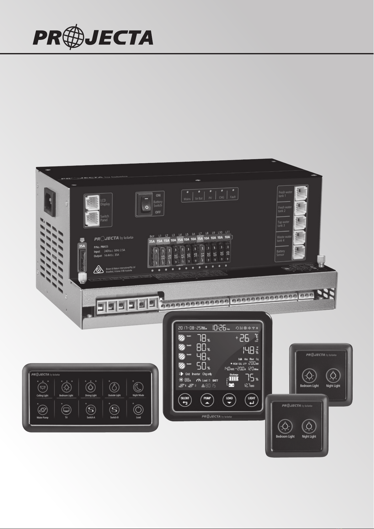
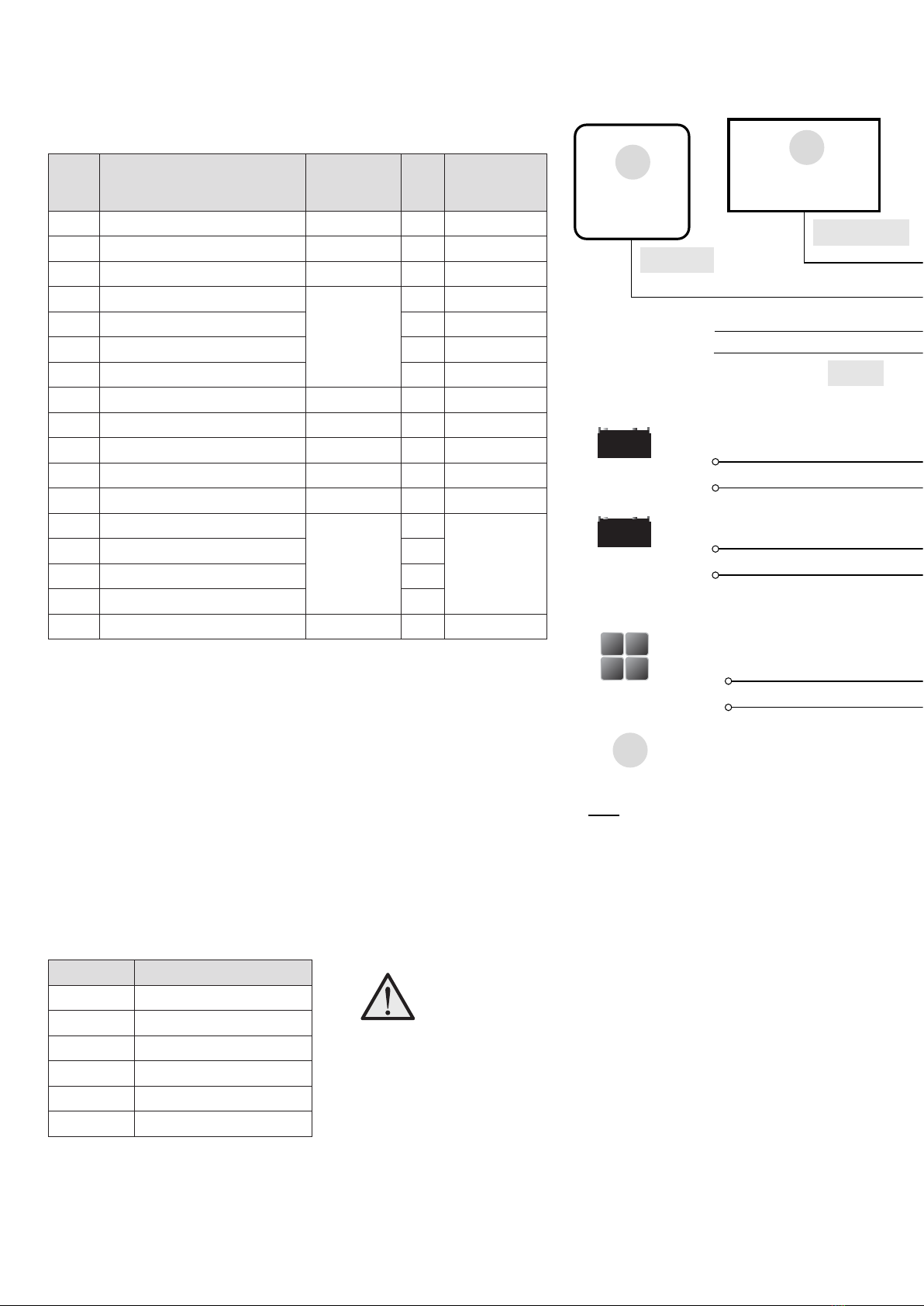
SYSTEM COMPONENTS:
1 Master Power Unit
2 Monitor with Bluetooth connectivity
3 10 position switch panel (not inc. PM435-BT)
4 4 Water tank sensors (not supplied)
5 2 x 2 Position switch panel (not inc. PM435-BT)
6 Cables (Refer to Chapter 4.1 for the cable list)
Figure 1 System Components for PM400 & PM435-BT
P/No. PMLCD-BT
Fresh Water Tank 1 Probe
(Not supplied)
Fresh Water Tank 2 Probe
(Not supplied)
Tap Water Tank Probe
(Not supplied)
Waste Water Tank Probe
(Not supplied)
P/No. PM4SW10
(Not inc. PM435-BT)
2 x P/No. PM4SW2
(Not inc. PM435-BT)
PV
Service Battery
Starter Battery
P/No. PMWS200 or PMSW400
P/No. PMWS200 or PMSW400
P/No. PMWS200 or PMSW400
P/No. PMWS200 or PMSW400
Battery Temperature
Sensor P/No. PM30
P/No. PM435

5
1.1 Features
• Smart battery charger 12V 35A (30A for charging current)
• Multi stage adaptive charging algorithm
• Active Power Factor Correction PFC charging
• Temperature compensation Charging
• Voltage compensation Charging
• Float Charge for starter battery
• 30A MPPT Solar charge controller
• Built-in 14 outputs
• 11 x fused outputs
• Battery charging relay 12V 60A – 60A continuously, 100A 30mins
• Battery Low Voltage Protection (Low Voltage Disconnect)
• Built-in Battery Switch
• Support external remote battery switch
• Built-in shunt for precise battery measurement
• Control one water pump with four tank probes
• Thermal controlled fan
• Spring terminal & Screw terminal
• T-bus compatible
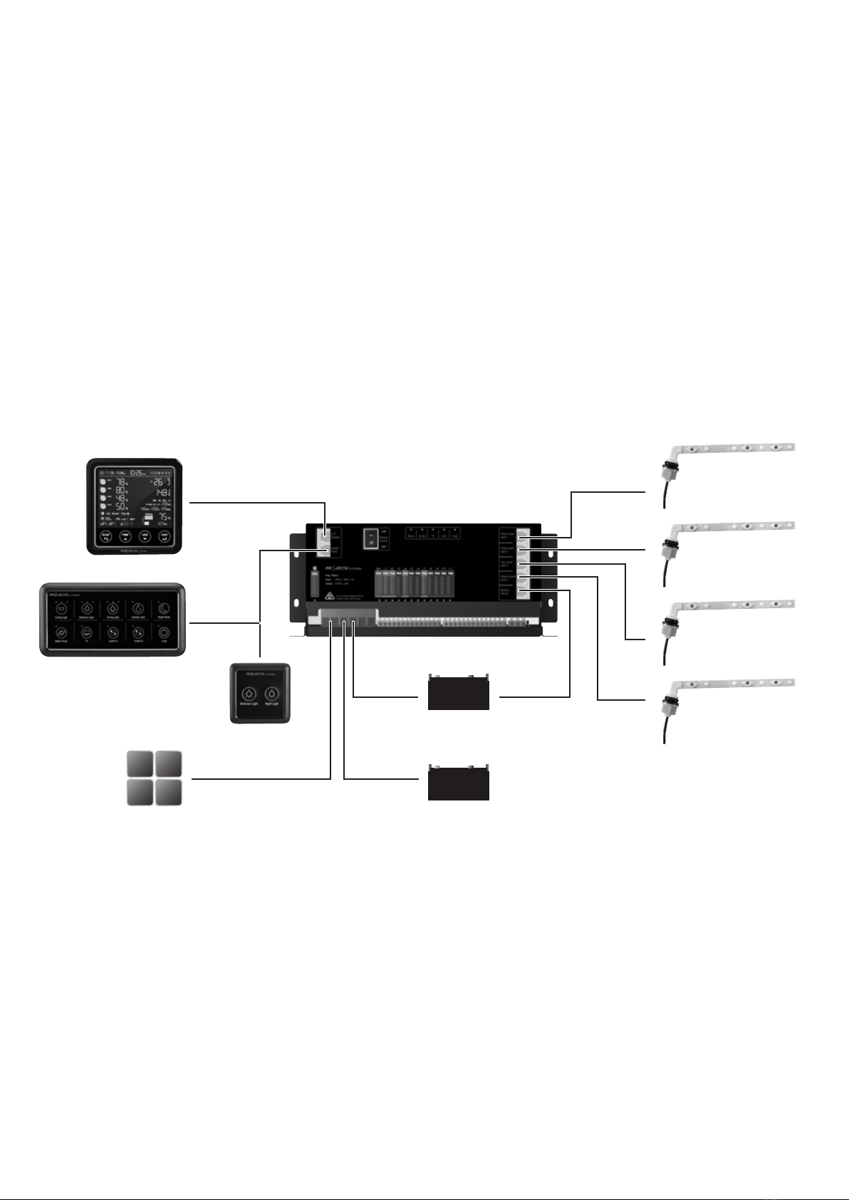
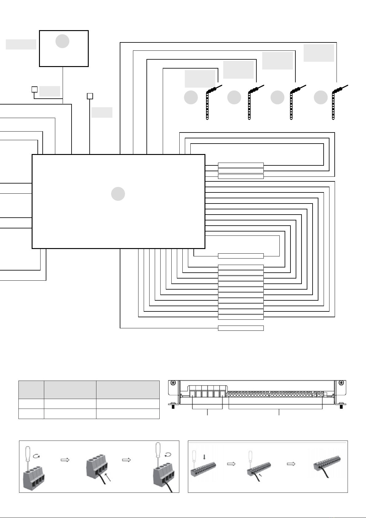
Figure 2 System Schematic
6
1.2 Monitor
The monitor is a digital control center for complete on-board power system.
Features:
• T-Bus design (can be connected to multiple devices)
• System monitoring
• Conguration
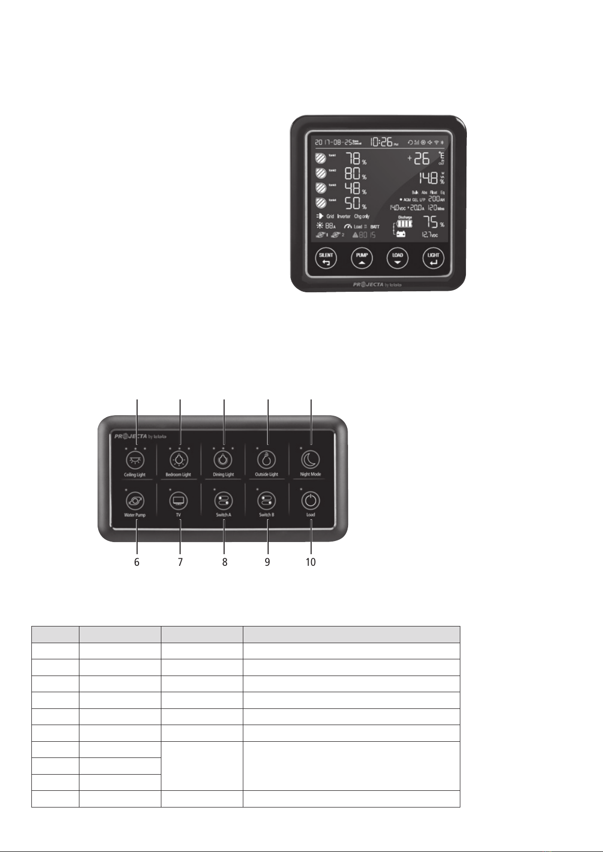
Figure 3 Overview of Monitor
1.3 10-Position Switch Panel (not inc. PM435-BT)
PM4SW10 switched panel was precongured with functions listed as below Table 1
Figure 4 Overview of 10 Position Switch Panel
PM4SW10
No. LABEL TYPE DESCRIPTION
1Ceiling light DC load control Load control, support brightness adjustment
2Bedroom light DC load control Load control, support brightness adjustment
3Dining light DC load control Load control, support brightness adjustment
4Outside light DC load control Load control, on/off control
5Night mode Scene mode Refer to Chapter 2.11
6Water pump DC load control Load control, on/off control
7TV
DC load control Load control, on/off control8Switch A
9Switch B
10 Load DC load control Refer to Chapter 2.7
Table 1 Function list of PM4SW10
1 2 3 4 5
6 7 8 9 10

7
1.5 Water Tank Probe
For PM435, a maximum of 4 probes can be monitored.
NOTE: Always check the probe required for the water tank before purchase. There are 2 probe styles:
Figure 6 PMWS200 Figure 7 PMWS400
PMWS200:
• Side installation
• Suitable for water tank
• Depth >200mm
PMWS400:
• Side installation
• Suitable for water tank
• Depth 300-400mm
1.4 Bedroom Switch Panel (not inc. PM435-BT)
With two bedroom switches, the PM400 offers extra customisation
Figure 5 An overview of Switch Panel
PM4SW2
No. NAME TYPE DESCRIPTION
1Bedroom light DC load control Load control, support brightness adjustment
2Night light Scene mode Load control, support brightness adjustment.
Refer to Chapter 2.11
Table 2 Function list of PM4SW2
Note: Dimming function may not be compatible with some capacitive touch lights..
8
2. KEY FEATURES AND FUNCTIONS
2.1 Multiple Inputs
AC MAINS x x
SOLAR x x
STARTER BATTERY x x
DOMINATING SOURCE AC MAINS AC MAINS STARTER
BATTERY
Table 3 Input Priority
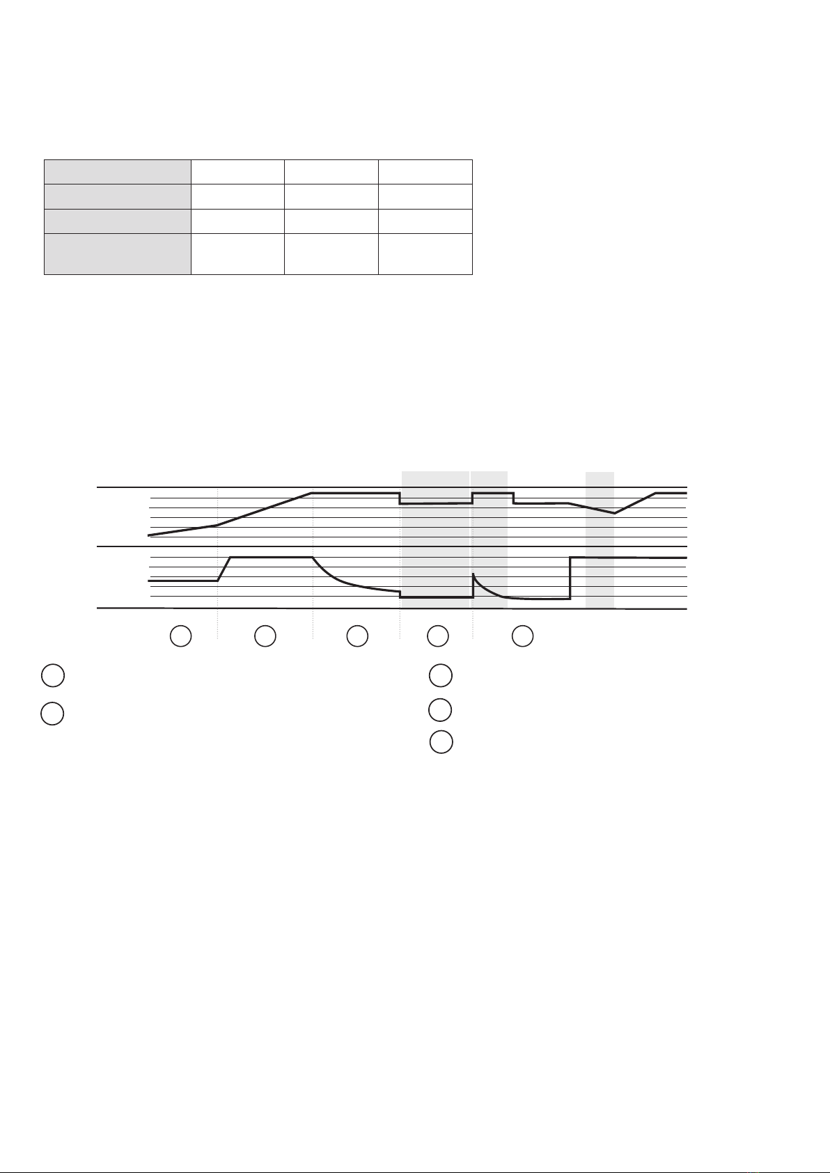
Figure 8 Charging Algorithm
Battery Temperature Sensor
The BTS P/n: PM30 (Battery Temperature Sensor) supplied with PM435, measures the temperature of the
battery and automatically adjusts, in real time, to charge the battery properly at compensation rate of –
4mv±10%/°C/cell. In case BTS is not present, the PM435 will use 25°C as default.
Voltage Compensation Charging
With a voltage sensor the PM435 can, automatically adjust its output to compensate the voltage drop caused
by a cable. This assures the right voltage is being delivered for optimal charging.
Adjustable Charging Capacity
Users can adjust the charging current by specifying the battery capacity. The charging current is set at threshold
rate of 10% the of the battery capacity (I = 0.1C) by default.
Lithium Battery Charging
The PM435 can be congured to charge Lithium Iron Phosphate batteries. With the Lithium battery, the max
charging current will automatically be set at 30% of battery capacity (Imax=0.3C).
½ lcc
lcc
11.5V
10 days 1 hr 5mins
SOFT START
STAGE
CURRENT
VOLTAGE
BULK ABSORPTION FLOAT RECYCLE
1 2 3 4 5
1
2
3
4
5
The PM435 accepts inputs from AC mains, Solar and Starter Battery (Alternator). However,
only one source will provide power at one time, see table below for details:-
2.2 Battery Charger Of Stationery/Service Battery
The charger automatically starts when the appropriate qualied power is connected, either from grid, generator or solar.
With multiple charging stages (soft start-bulk absorption oat-recycle), PM435 is designed to fully charge the battery quickly. To guarantee
the optimal charging for batteries of different states, the PM435 features Microprocessor-controlled charging algorithm.The Float and
Recycle charging programs guarantees that the battery condition does not change despite being connected for a longer period.
SOFT START
Increases battery life by gently starting to charge the battery
5% of bulk
BULK
Reduces charging time by delivering maximum charge to set
voltage life by gently starting to charge the battery 25% of bulk
ABSORPTION
Ensures a full charge to the battery without overcharging
FLOAT
Float charge maintains the battery at 100% charge
RECYCLE
9
2.3 Vehicle Battery Charger
Along with a powerful charger for service battery, PM435 offers a oat charge of up to 3A to keep the starter battery charged, whether
connected to the AC main or PV.When the starter battery is less than 12.4V, the PM435 starts charging after 30 minutes delay and stops
charging when voltage reaches 12.8V.
2.4 Power Supply Mode
If no battery is attached to PM435 unit, it will work as a power supply automatically with a 12.8VDC output.
2.5 MPPT Solar Charger Controller
PM435 has a built-in MPPT charger for the service battery with:
• Max input voltage 50VDC
• Max charging current 30A
• Max supply current 30A
2.6 Voltage Charging Relay (VCR or commonly known as a VSR)
PM435 master power unit has a built-in voltage charging relay (VCR), which offers a convenient source to charge the service battery by
alternator whilst the engine is running.
LEAD ACID BATTERY – When the starter battery reaches 13.4VDC with threshold time delay, the VCR will charge the service battery from
the alternator. VCR will continue charging until the starter battery voltage drops under 12.8VDC.
LifePO4LITHIUM BATTERY – When the starter battery reaches 14.0VDC with threshold time delay, the VCR will charge the service battery
from the alternator. VCR will continue charging until the starter battery voltage drops below 13.5VDC and less than 2A charge to service
battery with threshold time delay.
NOTE: The PM435, when charging from the starter battery, does not provide 5 stage charging. It simply takes whatever power and
charging is available from the vehicle alternator.
NOTE: If your vehicle is tted with a smart charging system (Variable Voltage or Temperature Compensating), the VCR may not function
correctly and a DC-DC Charging system is recommended.
Please consult your local dealer or installer for further information.
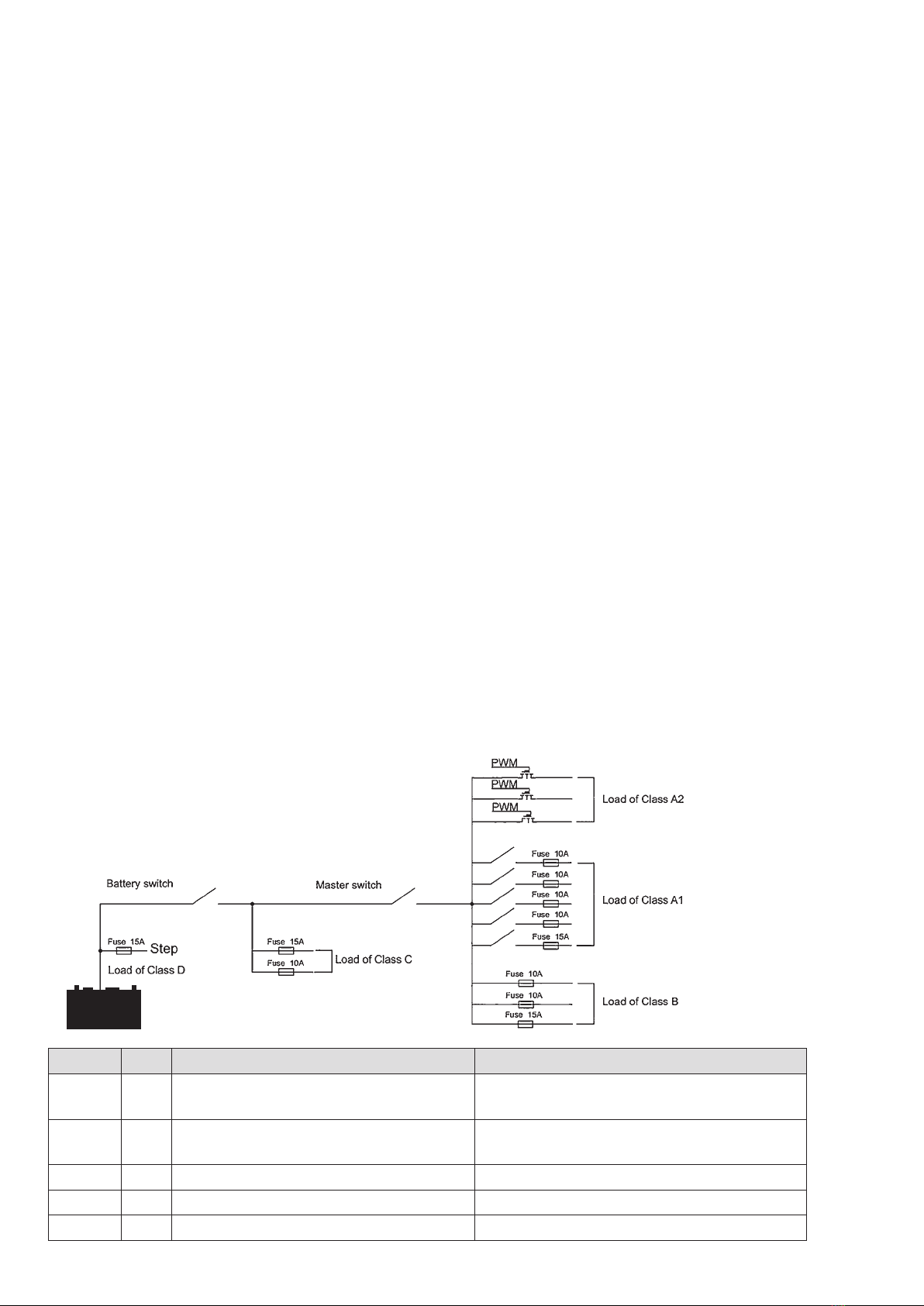
TYPE QTY DESCRIPTION POSSIBLE LOAD SUITABLE
Class A1 5Relay controlled output with fuse, protected by
main master switch relay
Water pump, Water tank heating, TV etc.
Class A2 3PWM controlled, protected by master switch
relay
General lighting, such as, Ceiling light, Dining light,
Bedroom light etc.
Class B 3Fused outputs, protected by master switch relay Ventilation fan etc.
Class C 2Always alive load Fridge, security alarm etc.
Class D 1Permanent on load Auto step
2.7 Categorised Outputs
The 14 outputs of PM435, are categorized into different groups for different controls.
Figure 9 Categorised output
Table 4 Categorized outputs denition

10
2.8 Battery Low Voltage Protection
(BLVP or commonly known as an LVD)
The PM435 unit has a built-in battery low voltage protection relay. It will disconnect the load once the battery voltage
drops below the threshold voltage. The default setting is 10.5Vdc and it can be changed by crystal central monitor or
mobile APP from 10.0Vdc to 11.7Vdc.
2.9 Battery Switch
The PM435 unit offers a convenient way to switch off the output of the service battery on-board. It protects the
service battery from being drained by electronics on board, completely isolating the battery. PM435 unit also supports
a remote manual battery switch. Before using the remote switch, ensure the ‘switch selector’ is set to ‘Remote’.The
switch is only effective when the system has no other energy resource for the load except the battery.
2.10 Precise Battery Measurement
PM435 unit has a battery measurement system controlled by microprocessor. It measures battery voltage, charge/
discharge current, remaining AH and display time to go.
Compared to conventional indicating meters, a small current can be measured and read accurately with this device.
With this feature, it highlights faults, alarms and installation errors.
ATTENTION: If you have loads connected directly on battery instead of PM435 Power Management System, the
measurement will not be accurate.
2.11 Scene mode setting
The PM435 supports the precongured scene mode for multiple loads controlled. There are two modes programmed
in MSP10 and MSP2.
“Night mode” on 10 Position Switch Panel (not inc. PM435-BT)
or “Silent” mode on the Monitor
By pressing “Night mode” on the switch panel or “Silent mode”, all LED indicators of the 10 Position Switch and
backlight of Monitor will be turned off; in the meantime, the output power of PM435 will be reduced in order to stop
the fan for a noiseless night.
“Night Light” on 2 Position Bedroom Switch (not inc. PM435-BT)
By pressing “Night Light”, the Ceiling light will be turned on, and by holding down “Night Light” button to adjust a
proper brightness for night without disturbing other’s sleeping. The brightness setting will be remembered.
11
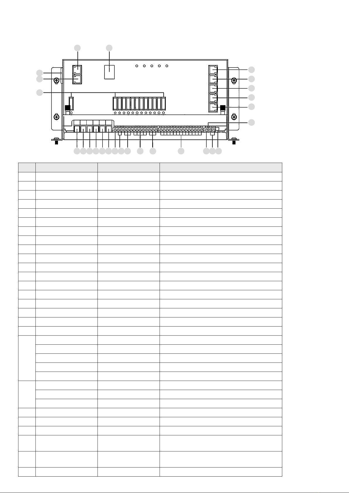
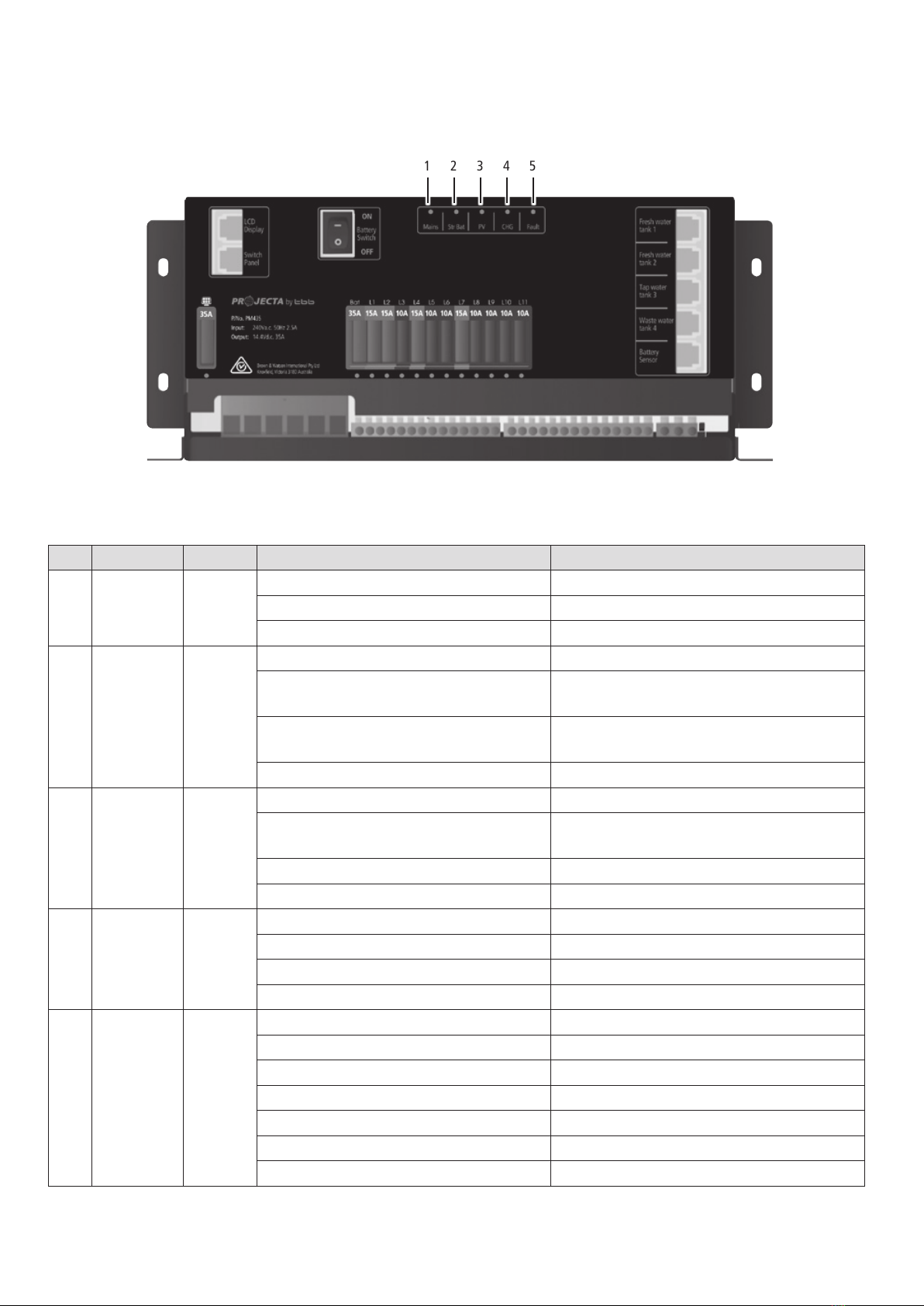
Figure 10 Front panel of PM435
No. LABEL DEFINITION DESCRIPTION
1Power AC input port
2Switch panel Comm port Connect to switch panel
3LCD Display Comm port Connect to Monitor
4Battery switch Service battery switch Manual battery switch
5Fresh water tank 1 Connect to fresh water tank 1
6Fresh water tank 2 Connect to fresh water tank 2
7Tap water tank Connect to tap water tank
8Waste water tank Connect to waste water tank
9Battery sensor For temp compensation Connect to service battery+
10 PV+ Solar input Connect to PV+
11 PV- Connect to PV-
12 Starter Bat+ Starter battery+ Connect to starter battery+ (<20Vdc)
13 Service Bat+ Service battery+ Connect to service battery+ (<20Vdc)
14 Starter Bat- Starter battery- Connect to starter battery-
15 Service Bat- Service battery- Connect to service battery-
16 L1+ Step Connect to load of class D
17 L2+ ~ L3+ Connect to load of class C
18 L4+ ~ L6+ Connect to load of class B
19
L7+ Switch B Connect to Switch B+
L8+ Switch A Connect to Switch A+
L9+ Outside light Connect to Outside light+
L10+ TV Connect to TV+
L11+ Water pump Connect to Water pump+
20
L12+ Dining light Connect to Dining light+
L13+ Bedroom light Connect to Bedroom light+
L114+ Ceiling light Connect to Ceiling light+
21 L1- ~ L14- Connect to DC load -
22 D+ Point D+ input Connect to D+
23 Remote Switch Terminal block Connect to remote switch
24 Select Switch Dip switch Select local switch or remote switch (Notice: open the
upper cover board to operate)
25 Setting Dip switch Set the battery type and capacity (Notice: open the upper
cover board to operate)
26 Fuse Fuses with indicator for blown
3. STRUCTURE AND INSTALLATION
3.1 PM435 Power Management System
Table 5 Connection
of PM435
1
3 4
5
6
7
8
9
25
2
26
10 11 12 13 14 15 16 17 18 19 20 21 222324
12
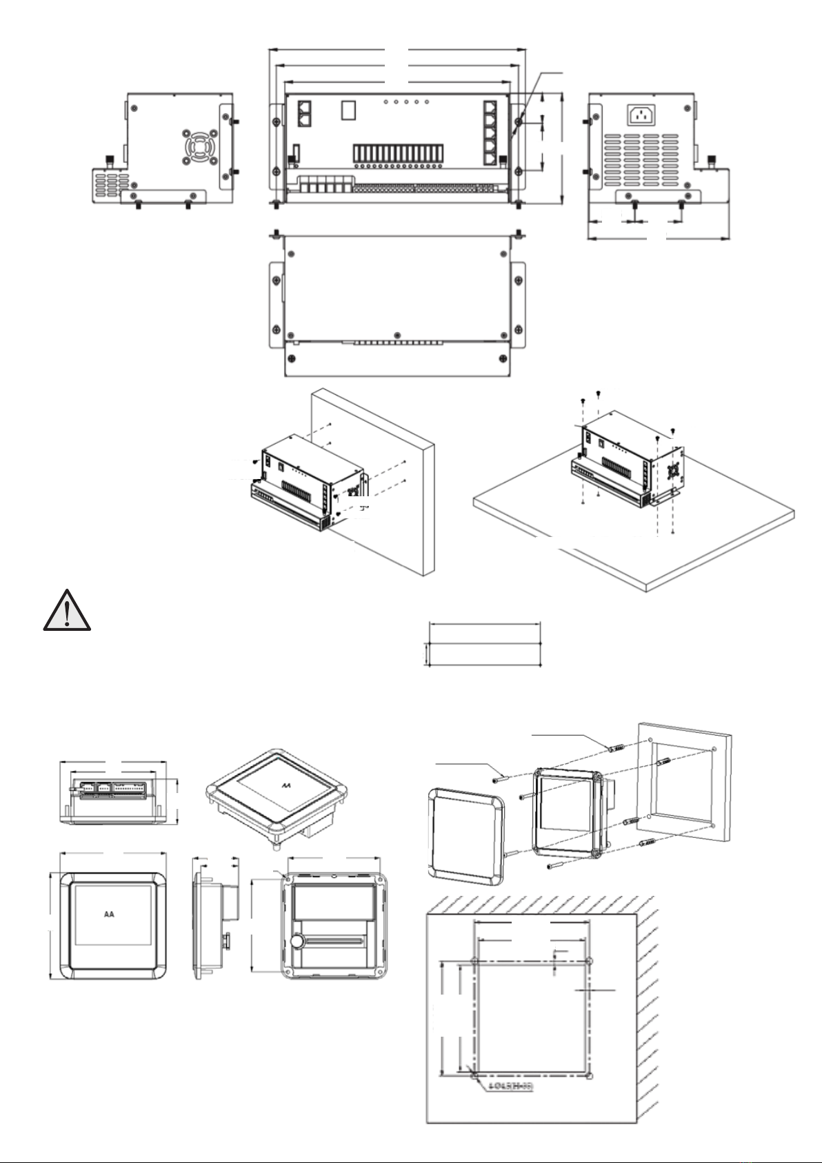
3.2 Monitor
Figure 13 Dimension of Monitor
(Unit: mm)
Figure 14 Installation of
Monitor (Unit: mm)
Installation
PM435 can be installed on a
horizontal surface or vertically
on a wall. Please see following
instructions:
Figure 12 Installation of PM435
(Unit: mm)
Ensure clearance on both
sides of PM435 unit upon
installation. A recommended
clearance of 5cm on each side.
Figure 11 Dimension of PM435
(Unit: mm)
Hole size
Installation
300
284
264
M4
35
55 129
53.5 55
165
284
101
81
101
4- Ø3.5
2.5
2.5
4- Ø4* Ø5*24
87.6
101
43.1
87.6
43.45
35.6
87.6 ±0.5
82.0
+2
87.6 ±0.5
82.0
+2
55
M420mm
M420mm
Vertical Installation
Hole size
Horizontal Installation
M420mm
4-M325mm
M420mm
M420mm
M420mm
M420mm
M420mm
13
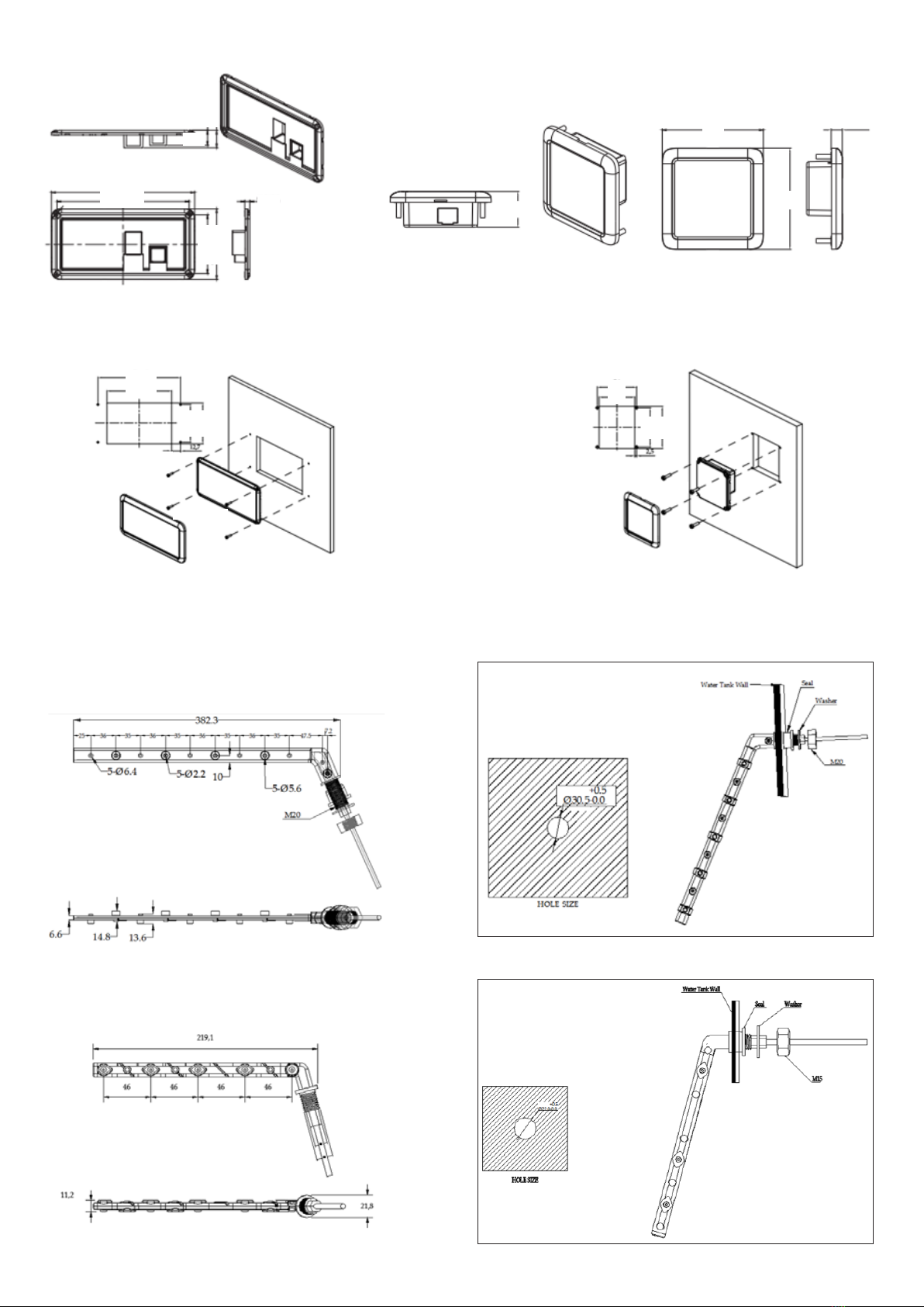
3.4 Water Tank Probe
3.4.1 PMWS400 Water Tank Probe
3.4.2 PMWS200 Water Tank Probe Installation
Figure 21 Dimension of PMWS200 (Unit: mm) Figure 22 Installation of PMWS200 (Unit: mm)
Installation
3.3 10 and 2 Position Switch Panel (not inc. PM435-BT)
Figure 15 Dimension of PM4SW10 (Unit: mm)
Installation
Figure 16 Dimension of PM4SW2 (Unit: mm)
Figure 17 Installation of PM4SW10 (Unit: mm) Figure 18 Installation of PM4SW2 (Unit: mm)
Figure 19 Dimension of PMWS400 (Unit: mm) Figure 20 Installation of PMWS400 (Unit: mm)
Hole size Hole size
19.6
185
170.5
75.5
91
172.5
135 54
49
78.5
85
54
58
22.9
65 7.1
65
6.6
4-M312mm
4-M312mm
14
4.3 Preparation
PM435 system is designed with concept of ‘Plug in and Play’ in mind. To complete the easy installation, a screw driver and DC cables are
required. Follow Table 5 recommendation for minimum wirings.
CURRENT MINIMUM CABLE SIZE
0–5A 1.0mm2 or 18 AWG
5–10A 2.0mm2 or 14 AWG
10–15A 3.0mm2 or 13 AWG
15–20A 4.0mm2 or 11 AWG
20–25A 5.0mm2 or 10 AWG
25–30A 6.0mm2 or 9 AWG
Table 7 Minimum cable size
4. WIRING
4.1 Material
Following components are delivered the PM400 package.
CODE NAME MODEL OR
LENGTH
QTY. PART No. ON
DRAWING
1Caravan Master Power PM435 1 1
2Monitor with Bluetooth PMLCD-BT 1 2
310 Position Switch Panel PM4SW10 1 3
4Fresh water tank 1 level sensor
Not Included
0 4
5Fresh water tank 1 level sensor 0 5
6Tap water tank level sensor 0 6
7Waste water tank level sensor 0 7
82 Position Switch Panel PM4SW2 2 8
9PV Not Included 0 9
10 Communication line – RS485 5m 1PMLCDC
11 Switch panel line 5m 1PM4SW10C
12 Battery sensor line 3m 1PMBS
13 Water tank probe line
Not Included
0
PMWS200 /
PMWS400
14 Water tank probe line 0
15 Water tank probe line 0
16 Water tank probe line 0
17 Power Cable 1.5m 1PMAC
4.2 System Schematic
When running cables, if they pass through panels or wall, ensure the
cables are protected from damage by sharp edges. In such cases, it is
recommended to use cable glands.
Table 6 Component list of PM435
1
4 5 6 7
2
PMLCDC
PMAC
PM4SW10C
PMBS
PMTS
PMWS200/
PMWS400
PMWS200/
PMWS400
PMWS200/
PMWS400
PMWS200/
PMWS400
PM4SW2
3
8
9
PM435
Monitor
Flexi Panel 100W
10 Pos. Switch
(not inc. PM435-BT)
2 Pos. Switch
(not inc. PM435-BT)
Outdoor
Temperature Sensor
Battery Temperature
Sensor and Terminal
Voltage
AC in
240V / 50Hz
~
L
N
BM COM
Service Batt –
Service Batt +
Service Battery
(12VDC)
Starter Batt –
Starter Batt +
Starter Battery
(12VDC)
PV –
PV +
PV in
Vmp: 17–50V
DC cable, supplied by client
Fresh Water
Tank 1
Level Sensor
Fresh Water
Tank 2
Level Sensor
Tap Water
Tank
Level Sensor
Waste Water
Tank
Level Sensor
N L
AC IN
Monitor Switch
Panel
Battery
Sensor
Waste
Water
Tank
Tap
Water
Tank
Fresh
Water
Tank 2
Fresh
Water
Tank 1
•
L12
•
L13
•
L14 L14
•
L13
•
L12
•
L11
•
L10
•
L9
•
L8
•
L7
•
L6
•
L5
•
L4
•
L3
•
L2
•
L1
•
PV
• •
D + Input
Remote Switch
Service
Batt -
Service
Batt +
Starter
Batt -
Starter
Batt +
L11L10 L9 L8 L7 L6 L5 L4 L3 L2 L1
• • • • • • • • • • •
Celing Light
Bedroom Light
Dining Light
Step
Refigerator
Load of Class C
Load of Class B
Load of Class B
Load of Class B
Switch B
Switch A
Outside Light
TV
Pump
D + Input
15
TYPE TERMINAL
MODEL NUMBER
SUITABLE CABLE
GAUGE
Type 1 ERTB10-10.16 0.5mm2 - 10mm2
Type 2 wago804-114 0.25mm2 - 2.5mm2
Figure 25 Connection of Terminal Type 1
4.2 System Schematic
TYPE 1 TYPE 2
Figure 26 Connection of Terminal Type 2
1
4 5 6 7
2
PMLCDC
PMAC
PM4SW10C
PMBS
PMTS
PMWS200/
PMWS400
PMWS200/
PMWS400
PMWS200/
PMWS400
PMWS200/
PMWS400
PM4SW2
3
8
9
PM435
Monitor
Flexi Panel 100W
10 Pos. Switch
(not inc. PM435-BT)
2 Pos. Switch
(not inc. PM435-BT)
Outdoor
Temperature Sensor
Battery Temperature
Sensor and Terminal
Voltage
AC in
240V / 50Hz
~
L
N
BM COM
Service Batt –
Service Batt +
Service Battery
(12VDC)
Starter Batt –
Starter Batt +
Starter Battery
(12VDC)
PV –
PV +
PV in
Vmp: 17–50V
DC cable, supplied by client
Fresh Water
Tank 1
Level Sensor
Fresh Water
Tank 2
Level Sensor
Tap Water
Tank
Level Sensor
Waste Water
Tank
Level Sensor
N L
AC IN
Monitor Switch
Panel
Battery
Sensor
Waste
Water
Tank
Tap
Water
Tank
Fresh
Water
Tank 2
Fresh
Water
Tank 1
•
L12
•
L13
•
L14 L14
•
L13
•
L12
•
L11
•
L10
•
L9
•
L8
•
L7
•
L6
•
L5
•
L4
•
L3
•
L2
•
L1
•
PV
• •
D + Input
Remote Switch
Service
Batt -
Service
Batt +
Starter
Batt -
Starter
Batt +
L11L10 L9 L8 L7 L6 L5 L4 L3 L2 L1
• • • • • • • • • • •
Celing Light
Bedroom Light
Dining Light
Step
Refigerator
Load of Class C
Load of Class B
Load of Class B
Load of Class B
Switch B
Switch A
Outside Light
TV
Pump
D + Input
Figure 23 System Schematic
4.4 Connection
PM435 unit is designed with a spring and screw terminal. Please refer to following illustration at right.
Each type of terminal is designed to t a different range of cables.
Table 8 Recommended terminal and cable gauge Figure 24 PM435 Terminal
Type 1 Type 2
16
No. LED COLOUR STATUS DESCRIPTION
1Mains GREEN
ON AC input OK
OFF AC disconnected
Quick ashing (ash twice every second) AC input abnormal
2Starter
Battery GREEN
ON Alternator charging the SERVICE battery
Slow ashing (ash once every second) Starter battery is >13.4V and is being charged by
the PM435
Quick ashing (ash twice every second) The Starter Battery is 2~13.4V or >16.0V, while
AC power is connected.
OFF Starter battery is disconnected.
3PV
(Solar) GREEN
ON Solar charging the battery
Slow ashing (ash once every second) The input voltage of the Solar is normal and the
service battery is charged by the AC or Alternator
Quick ashing (ash twice every second) PV input error
OFF PV disconnected
4CHG GREEN
ON Battery charged
Flashing (ash once every second) Battery charging
Slow ashing (1 second on 2 seconds off) Battery discharge
OFF Battery disconnected
5FAULT RED
ON Short circuit
Flash once per cycle Service battery voltage low
Flash twice per cycle Service battery voltage high
Flash 3 times per cycle PM435 unit Over Temperature
Flash 4 times per cycle Bulk charge timeout
Flash 5 times per cycle VCR anomaly
Flash 6 times per cycle Environment Over Temperature
Figure 27 An overview of PM435
5. DISPLAY
5.1 PM435 Power Management System
P/No. PM335
Table 9 LED indicator description of PM435
1 2 3 4 5

17
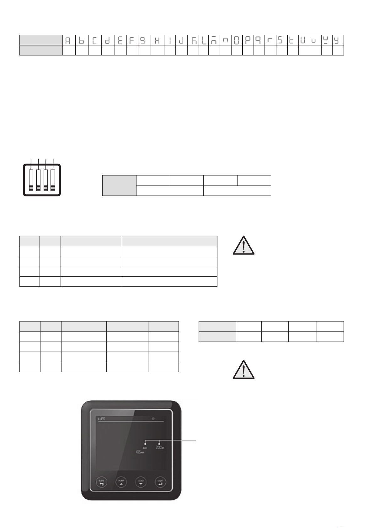
5.3 Monitor PMLCD-BT
5.2 10 Position Switch Panel PM4SW10 (not inc. PM435-BT)
5.2.1 2 Position Switch Panel PM4SW2 (not inc. PM435-BT)
Time
Figure 28 An overview of PM4SW10
No. NAME TYPE DESCRIPTION
1Ceiling light
DC load control
Load control, support
brightness adjustment.
May not be compatible with
capacitive touch lights
2Bedroom light
3Dining light
4Outside light Load control, on/off control
5Night mode Scene mode Refer to Chapter 2.11
6Water pump
DC load control Load control, on/off control
7TV
8Switch A
9Switch B
10 Load Refer to Chapter 1.3
1 2 3 4 5
6 7 8 9 10
Table 10 Button explanation of PM4SW10
No. NAME TYPE DESCRIPTION
1Bedroom light DC load control Load control, brightness
adjustment
2Night light Scene mode Load control, Brightness
adjustment, refer to Chapter
2.11
P3 P4 ADDRESS
On On 1#
On Off 2#
Off On 3#
Off Off 4#
Figure 29 An overview of PM4SW2 Table 11 Button explanation of PM4SW2
1 2
Figure 30 An overview of Monitor PMLCD-BT
TBA
Outdoor temperature
Output power
Charging state
Service battery:Type/Capacity
Service battery:Voltage/Current/Time to go
Service battery SOC (State of Charge)
Voltage of vehicle battery
VCR connection
Light/Enter/ Setting switch
Load/Down switch
Date
Water tank 1
Water tank 2
Water tank 3
Water tank 4
Power Source
Solar charge
Water pump 1/2
Alarm error code
Silent/Esc switch
Pump/Up switch
Table 12 Switch address settings of PM4SW2
When there are more than one
PM4SW2 in the system.The customer
should pay attention to the address
setting by dip switch P3 and P4 for
them.They should not be the same.

18
Figure 31 Switch ON /OFF Pump Figure 32 Switch ON/OFF all of the DC Loads
5.3.2 Switch Explanation
SWITCH FUNCTION DESCRIPTION
SILENT & Stop the fan ventilation in order to reduce the
noise Refer to 3.11 Press ‘Silent/Esc’ button until shows on the screen, then press
‘Light/Enter’.
PUMP & To switch on/off pump
Pump on: Pump off:
The detailed steps are shown as below Figure 31
LOAD & To switch off all the loads connected on DC
charger
The function is the same as Load switch in PM4SW10. The detailed steps
are shown as below Figure 32
LIGHT To adjust the brightness and switch off the
backlight of he monitor
Total three levels of brightness
LIGHT For
Setting
To set clock, battery battery tank quantity etc Hold down the ‘LIGHT’ button until the Date zone (Table 20) shows
the setting code. It means the unit enters the setting mode. For the full
details of setting codes, please refer to Chapter 6.2.1
PUMP PUMP LOAD LOAD
Load
Load
Load
OFF
OFF
ON
Load ON
5.3.1 Monitor Symbol Explanation
No. DESCRIPTION COMMENTS
1Water level 0%-25%-50%-75%-100%
Water Tank 1
EMPTY Flashing, the water is less than the recommended levelWater Tank 2
Water Tank 3
Water Tank 4 FULL Flashing, the gray water or waste water is more than the alarm level
2Working Mode GRID AC grid status
CHARGE ONLY Battery charger only
3Load
Status of DC-Load switch in system: on / off
BATTERY DC loads are powered by battery
4Water Pump
Pump 1 is ON
Pump 1 is OFF
5Alarm Error Code
Overload alarm
Over temperature alarm
System error code. Refer to the error codes on page 22
6VCR connection
Voltage charging relay (VCR) is connected
Voltage charging relay (VCR) is disconnected
7Output power Voltage of system output
Current of system output
Table 13 Monitor Symbol explanation
Load ON
!
Table 14 Switch explanation
19
5.3.3 Alphabet Explanation
CHARACTER
ALPHABET A B C D E F G H I J K L M N O P Q R S T U V X Y
Figure 33 Dip Switch of PM435 Table 16 Dip Switch denition
6. OPERATION
If there is conict between the conguration on PM400 and the monitor, the monitor will ash as a reminder.
6.1 Conguration on PM435
If there is conict between the conguration on PM435 and the monitor, the monitor will ash as a reminder.
6.1.1 Battery Capacity and Battery Type
There is a dip switch for you to set battery capacity and battery type.
DIP
SWITCH
1234
Battery Capacity Battery Type
Dip switch denitions:
Table 17 Battery capacity setting by dip switch
Table 18 Battery type setting by dip switch
DIP SWITCH 1 2 3 4
STATUS OFF OFF OFF OFF
Factory default setting
Congure the Max Charging Current of PM435
Congure the Battery Type Installed
DS1 DS2 BATTERY CAPACITY CHARGING CURRENT OF PM435
ON ON 100Ah 10A
ON OFF 150Ah 15A
OFF ON 200Ah 20A
OFF OFF 300Ah 30A
When choosing max charging current,
please take into consideration
the consumption of the DC load
connected with the system.
Settings of ‘Battery Type’ and
‘Battery Capacity’ need to be the
same at both the PM435 dip switch
and the monitor.
DS3 DS4 BATTERY TYPE ABSORPTION FLOAT
OFF OFF AGM 14.4V 13.5V
OFF ON GEL 14.1V 13.5V
ON OFF LFP (LiFePO4) 14.4V 13.5V
ON ON WET 14.7V 13.7V
1 2 3 4
ON
OFF
Figure 34 Reminder when conict setting between PM435 and Monitor
When the battery type and
capacity setting on the monitor
is not the same as PM435 dip
switch, the icons are ashing.
Table 19 Factory default setting
Table 15 Alphabet explanation
20
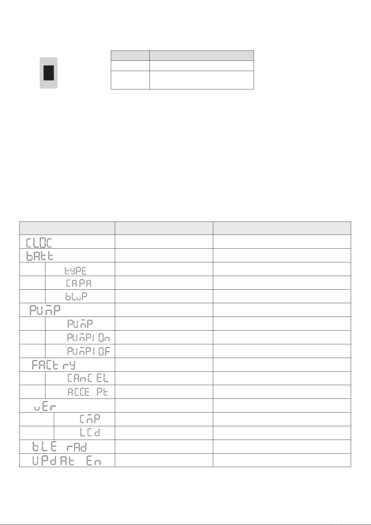
CODE FUNCTION DESCRIPTION
Time Setting Set date system 12H/24H and date.
Battery Setting
Battery Type AGM / GEL / LFP (LiFePO4)/WET
Battery Capacity
Battery Low Voltage Protection To shutdown the output of loads
Pump Pumps enable or disable
Pump 1 Select Pump 1
Pump 1 ON Pumps 1enable
Pump 1 OFF Pump 1 disable
Restore factory defaults
Cancel Cancel to restore factory defaults
Accept Conrm to restore factory defaults
Version Software version of devices. read only
CMP Software Version of PM435
LCD Software Version of LCD
Cut off BlueTooth Shut down connection of Crystal to APP
Update enable Enable to update rmware
1
6.1.2 Select Battery Switch Local/Remote
This function offers a possibility for user to use a remote battery switch to power on/off the service battery output
DIP SWITCH DESCRIPTION
Local The switch on PM435 unit works
Remote The remote switch works and local one
is disabled
Figure 35 Local/Remote Select Switch
Local
Remote
Table 21 Setting code of the Monitor
6.2 Conguration on Monitor
Access to the conguration menu is safeguarded with a passcode. The default is 0000 and may be set by a user.
PASSCODE DESCRIPTIONS
0000 Factory Default, no passcode
1999 Factory access passcode
XXXX User dene
Press the ‘Light’ button until the setting code is showing on the date time area which means the monitor is ready
for conguration. The ‘PUMP’ button and ‘LOAD’ button can be used to scroll through the conguration menu.
Table 20 Local/Remote Setting
This manual suits for next models
7
Table of contents


