Truma DuoComfort User manual

Page 72
Gebrauchsanweisung Seite 2
Einbauanweisung Seite 8
Im Fahrzeug mitzuführen!
Operating instructions Page 11
Installation instructions Page 17
To be kept in the vehicle!
Mode d’emploi Page 20
Instructions de montage Page 26
À garder dans le véhicule !
Istruzioni per l’uso Pagina 30
Istruzioni di montaggio Pagina 37
Da tenere nel veicolo!
Gebruiksaanwijzing Pagina 40
Inbouwhandleiding Pagina 46
In het voertuig meenemen!
Brugsanvisning Side 49
Monteringsanvisning Side 55
Skal medbringes i køretøjet!
Bruksanvisning Sida 58
Monteringsanvisning Sida 64
Skall medföras i fordonet!
DuoComfort

2
DuoComfort
Inhaltsverzeichnis
Verwendungszweck ......................................................................... 2
Sicherheitshinweise ...................................................................... 3
Gebrauchsanweisung
Bedien-/Anzeigeelemente ................................................................. 4
Inbetriebnahme ................................................................................. 4
Umschalten ....................................................................................... 4
Entnahmestatus ................................................................................ 5
Flaschenwechsel ............................................................................... 5
Schlauchwechsel .............................................................................. 6
Betrieb mit nur einer Gasflasche ...................................................... 6
Dichtigkeitsprüfung des Hochdruckbereichs ................................... 6
Zubehör ........................................................................................... 7
Technische Daten .......................................................................... 7
Einbauanweisung
Sicherheitshinweise ...................................................................... 8
Schutz vor Verschmutzung / Verölung ............................................. 8
Einbau und Anschluss des Umschaltventils .................................... 9
Verwendete Symbole
Einbau und Reparatur
darf nur vom Fachmann
durchgeführt werden.
Symbol weist auf mögli-
che Gefahren hin.
Hinweis mit Informationen
und Tipps.
Verwendungszweck
Truma DuoComfort ist ein au-
tomatisches Umschaltventil für
eine Zweiflaschenanlage. Es
ermöglicht einen Gasflaschen-
wechsel ohne Unterbrechung
der Gasversorgung.

3
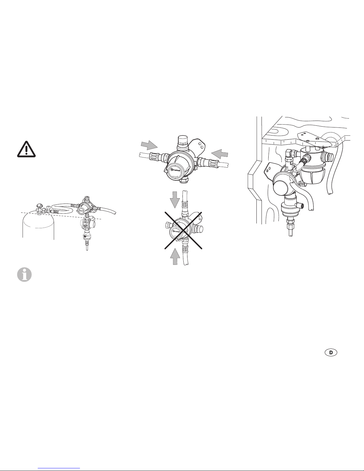
Die DuoComfort muss in Verbin-
dung mit einer nachgeschalteten,
wandmontierten Gasdruck-Regel-
anlage, z. B. MonoControl CS oder
GOK Typ EN61-DS (Eingangs-
anschluss mit Außengewinde
M20 x 1,5) betrieben werden. Die
Verwendung anderer Gasdruck-
Regelanlagen ist verboten.
Das Umschaltventil DuoComfort
ist für gewerblich genutzte
Fahrzeuge (z. B. in Deutschland
nach DGUV Vorschrift 79 – bisher
BGV D 34) einsetzbar.
Die Verwendung der DuoComfort
in geschlossenen Räumen
(z. B. Haushalt), Booten oder in
EX-Zone0 (z. B. Tankwagen) ist
verboten.
Für eine mögliche Verwendung
in Mobilheimen müssen die
nationalen Vorschriften beachtet
werden. In Deutschland ist die
Verwendung in Mobilheimen
verboten.
Sicherheitshinweise
– Für den Betrieb des Umschalt-
ventils, Gasgeräten bzw. Gas-
anlagen ist die Verwendung
von stehenden Gasflaschen
aus denen Gas aus der Gas-
phase entnommen wird
zwingend vorgeschrieben.
Gasflaschen aus denen Gas
aus der Flüssigphase entnom-
men wird (z. B. für Stapler)
sind für den Betrieb verboten,
da sie zur Beschädigung der
Gasanlage führen.
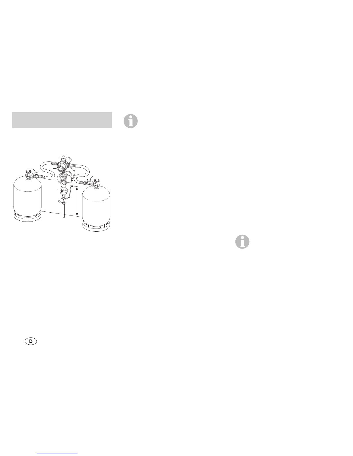
– Zum Anschluss an die Gasfla-
schen sind zwei Hochdruck-
schläuche erforderlich. Die
hierfür notwendigen Hoch-
druckschläuche bietet Truma
in den gängigsten Anschlussva-
rianten für europäische Gasfla-
schen an (siehe Seite67– 68).
– Zum „Betrieb der Gasanla-
ge während der Fahrt“ sind
Hochdruckschläuche mit
eingangsseitiger Schlauch-
bruchsicherung (SBS) zwin-
gend erforderlich. Siehe
Hinweise in der entspre-
chenden Gebrauchsanwei-
sung der nachgeschalteten
Gasdruck-Regelanlage.
– Druckregelgeräte und
Schlauchleitungen müssen
spätestens 10 Jahre (bei ge-
werblicher Nutzung 8 Jahre)
nach Herstellungsdatum
gegen neue ausgewechselt
werden. Der Betreiber ist dafür
verantwortlich.
– Um Störungen der Gasanlage
im Winterbetrieb zu verhin-
dern, kann das Umschaltventil
DuoComfort mit der Truma
Reglerbeheizung EisEx (Art.-
Nr. 53101-01) ergänzt werden.

4
Bedien-/Anzeigeelemente
DuoComfort
min.
50 cm
a
d
d
b
c
Bild 1 – Beispiel MonoControl CS
a = Drehknopf für Betriebs-/
Reserveflasche
b = Statusanzeige – Betriebs-/
Reserveflasche (grün/rot)
c = Grüner Resetknopf – Crash-
sensor-Auslöseelement
d = Grüne Taste
– Schlauchbruchsicherung
Als Zubehör liefert Truma
eine Fernanzeige (Art.-Nr.
50210-01), die den Status der
Betriebsflasche im Fahrzeug-
innenraum anzeigt.
Inbetriebnahme
– Zum Beispiel Drehknopf (a)
bis zum Anschlag nach links
drehen (linker Anschluss =
Betriebsflasche).
– Gasflaschen anschließen und
den ordnungsgemäßen Zu-
stand aller Schlauchverschrau-
bungen prüfen.
– Ventile beider Gasflaschen
öffnen.
– Schlauchbruchsicherung (d
– grüne Taste) für circa 5 Se-
kunden kräftig drücken. Im
Sichtfenster (b) wechselt die
Anzeige auf grün.
Gebrauchsanweisung – Gasdruck-Regelanlage in Be-
trieb nehmen (siehe entspre-
chende Gebrauchsanweisung).
Umschalten
Sinkt der Flaschendruck der
Betriebsflasche unter 0,5 bar,
schaltet das Ventil automatisch
um und es wird Gas aus der
zweiten Gasflasche entnommen.
Im Sichtfenster wechselt die An-
zeige auf rot.
Bei großer Kälte sowie bei
hoher Gasentnahme über
einen längeren Zeitraum kann
der Gasdruck unter 0,5 bar fal-
len, obwohl sich noch ein Rest
Gas in der Flasche befindet. Da-
durch kann es vorkommen, dass
Gas aus beiden Gasflaschen
gleichzeitig entnommen wird.
Bei Bedarf kann mit dem Dreh-
knopf (a) manuell bestimmt

5
werden, welche Flasche die Be-
triebs- bzw. Reserveflasche ist.
Drehknopf (a) immer bis zum
Anschlag nach links oder rechts
drehen (die Mittelstellung be-
wirkt eine gleichzeitige Entnah-
me aus beiden Gasflaschen).
Entnahmestatus
Bei der Grundstellung (Betriebs-
flasche linke Seite, Reservefla-
sche rechte Seite) ergibt sich
folgende Anzeige:
– Statusanzeige (b) ist grün =
Gasentnahme aus der linken
Flasche (Betriebsflasche).
– Statusanzeige (b) ist rot =
Gasentnahme aus der rechten
Flasche (Reserveflasche).
Flaschenwechsel
Gasrest: Nicht rauchen,
keine offenen Flammen!
DuoComfort bietet die Mög-
lichkeit, eine leere Gasflasche
auszuwechseln, ohne den Betrieb
der Verbrauchsgeräte zu unter-
brechen. In die Eingangsstutzen
integrierte Rückschlagventile ver-
hindern ein Ausströmen von Gas,
wenn kurzzeitig nur eine Gasfla-
sche angeschlossen ist (siehe „Be-
trieb mit nur einer Gasflasche“).
– Drehknopf (a) um 180° bzw.
eine halbe Drehung bis zum
Anschlag drehen und die ehe-
malige Reserveflasche wird
zur Betriebsflasche. Nach dem
Flaschenwechsel steht die
volle Gasflasche wieder als
Reserveflasche zur Verfügung.
Die Statusanzeige (b) wechselt
auf grün.
– Ventil der leeren Gasflasche
zudrehen und den Hochdruck-
schlauch abschrauben.
– An volle Gasflasche den Hoch-
druckschlauch anschrauben
und das Flaschenventil öffnen,
gegebenenfalls Schlauch-
bruchsicherung (d) für circa
5Sekunden kräftig drücken.
Die Statusanzeige (b) bleibt
auf grün.
Schlauchanschluss am
Flaschenventil nach jedem
Eingriff auf Dichtigkeit prüfen
(siehe „Dichtigkeitsprüfung des
Hochdruckbereichs“).

6
Schlauchwechsel
Gasrest: Nicht rauchen,
keine offenen Flammen!
Zum An- und Abschrauben der
Schläuche empfehlen wir die
Truma Schraubhilfe (Art.-Nr.
50020-61500). Sie gewährleistet
das nötige Anzugsmoment und
verhindert Beschädigungen an
der Verschraubung durch fal-
sches Werkzeug.
– Gasflaschenventil schließen.
– Hochdruckschlauch von der
Gasflasche (bzw. vom Aufstec-
kadapter) und vom Eingang
DuoComfort abschrauben.
– Länderspezifischen Hoch-
druckschlauch am Eingang
DuoComfort und an die
Flasche (bzw. am Aufsteck-
adapter) anschrauben.
– Gasflaschenventil öffnen.
– Gegebenenfalls Schlauch-
bruchsicherung (d) für circa
5Sekunden kräftig drücken.
– Gasdruck-Regelanlage in Be-
trieb nehmen (siehe entspre-
chende Gebrauchsanweisung).
Beim Schlauchwechsel si-
cherstellen, dass die dem
Schlauch beiliegende Dichtung
(Schlauchausgang – Eingang
Umschaltventil) ordnungsgemäß
installiert und nicht beschädigt ist.
Wir empfehlen, die Dich-
tung (Art.-Nr. 50020-76300)
bei jedem Schlauchwechsel zu
erneuern.
Den Schlauchanschluss am
Flaschenventil und am Eingang
DuoComfort nach jedem Ein-
griff auf Dichtigkeit überprüfen
(siehe „Dichtigkeitsprüfung des
Hochdruckbereichs“).
Betrieb mit nur einer Gas-
flasche
DuoComfort kann auch mit
nur einer Gasflasche betrieben
werden. In den Eingangsstutzen
integrierte Rückschlagventile
verhindern ein Ausströmen von
Gas aus dem freien Stutzen.
– Beim Einflaschen-Betrieb
muss der freie Eingang mit
beiliegendem Blinddeckel
(Messing) verschlossen
werden.
– Drehknopf (a) in Richtung der
Betriebsflasche stellen.
Dichtigkeitsprüfung des
Hochdruckbereichs
Die Dichtigkeitsprüfung des
Mittel- und Niederdruckbe-
reichs muss vom Fachmann
durchgeführt werden. Darü-
ber hinaus empfehlen wir eine

7
Überprüfung des Hochdruckbe-
reichs durch den Betreiber der
Gasanlage bei jedem Flaschen-
oder Schlauchwechsel.
Insbesondere die Verschraubun-
gen am Gasflaschenventil und
am Umschaltventil mit geeig-
neten Mitteln – beispielsweise
mit einem Lecksuchspray nach
DIN EN 14291 – auf Dichtigkeit
prüfen.
Zubehör
Hochdruckschläuche
(mit Schlauchbruchsicherung)
siehe Seite 67 – 68
Anschlussschlauch 1,5 m
zum Anschluss externer
Gasflaschen (G.5;
Art.-Nr. 50020-61300)
Ersatzdichtungen
für Hochdruckschläuche
(G.13 bzw. M20 x 1,5;
Art.-Nr. 50020-76300)
EisEx, Reglerbeheizung
(Art.-Nr. 53101-01)
Fernanzeige (inklusive EisEx)
zur Anzeige des Entnahmestatus
im Fahrzeuginnenraum
(Art.-Nr. 50211-01)
Winkelverschraubung 90°
(Art.-Nr. 50020-56000)
Ergänzungssatz
wird benötigt bei Gasflaschen-
Abständen von mehr als 100 cm
(Art.-Nr. 50020-61100)
Gasfernschalter
zum Absperren der Gasversor-
gung vom Fahrzeuginnenraum
GS 8 (Art.-Nr. 57014-01)
GS 10 (Art.-Nr. 57024-01)
Schraubhilfe
(Art.-Nr. 50020-61500)
Gasfilter
passend für alle wandmontierten
Umschaltventile mit Eingangs-
verschraubung M20 x 1,5 (Au-
ßengewinde – G.13). Montage
vor dem Umschaltventil.
(Art.-Nr. 50600-01)
Technische Daten
ermittelt nach EN 16129:2013
bzw. Truma Prüfbedingungen
Gasart
Flüssiggas (Propan, Butan)
Eingangsdruck
0,95 – 16 bar
Ausgangsdruck
0,3 – 0,9 bar
Nennumschaltdruck (pdi)
750 mbar
Ventileingang
Außengewinde M20 x 1,5 (G.13)

8
Einbauanweisung
Einbau und Repa-
ratur darf nur vom
Fachmann durch-
geführt werden.
Vor den Arbeiten
Einbauanweisung sorgfältig
durchlesen und befolgen!
Die Missachtung der Ein-
bauvorschriften bzw. ein
falscher Einbau kann zur Gefähr-
dung von Personen und zu Sach-
schäden führen.
Sicherheitshinweise
– Gasrest: Nicht rauchen, keine
offenen Flammen!
– Für die Sicherstellung der
korrekten Funktion muss die
Gasdruck-Regelanlage an
Ventilausgang
Überwurfmutter M20 x 1,5 (H.20)
Empfohlenes Anzugsmoment
3 – 5 Nm für Überwurfmutter
M20 x 1,5 (G.13, H.20)
Betriebstemperatur
-20 °C bis +50 °C
Produkt-Ident-Nummer
CE-0085BQ0102
DG approval number: 3894
Technische Änderungen vorbehalten!
einer stabilen Wand / Decke
fest angeschraubt werden
(mit 2 Schrauben).
– DuoComfort muss je nach
Ausführung vertikal an einer
stabilen Wand oder horizon-
tal an der Decke des Gas-
flaschenkastens eingebaut
werden.
– Die Einbaurichtung muss be-
achtet werden.
Schutz vor Verschmut-
zung / Verölung
Für den sicheren Schutz der
Gasdruck-Regelanlage vor
Verschmutzung / Verölung ist
der Einbau eines Truma Gas-
filters vor jedem Eingang der
Gasdruck-Regelanlage erfor-
derlich. Eine Gebrauchs- und
Einbauanweisung liegt dem
Gasfilter bei.

9
Einbau und Anschluss des
Umschaltventils
Das Umschaltventil
DuoComfort muss so
montiert werden, dass die Ein-
gänge mindestens auf Höhe
des Flaschenventils angebracht
werden.
Bild 2
Die Montage oberhalb der
Flaschenventile erschwert
das Eindringen von Gas in Flüs-
sigphase in das Umschaltventil,
vor allem während der Fahrt.
Das Umschaltventil DuoComfort
muss so montiert werden,
dass die Anschlüsse der
Hochdruckschläuche waage-
recht angeordnet sind.
DuoComfort
Bild 3
DuoComfort
Bild 4
Ist die Höhe im Flaschenkasten
eingeschränkt, empfehlen wir
das Umschaltventil DuoComfort
z. B. mit der Winkelverschrau-
bung (Art.-Nr. 50020-56000) an
der Flaschenkastendecke zu
befestigen.
Bild 5
Das Umschaltventil DuoComfort
wird eingangsseitig über das
Außengewinde M20 x 1,5 (G.13)
an die Hochdruckleitung und
ausgangsseitig über eine Über-
wurfmutter M20 x 1,5 (H.20) an
die nachgeschaltete Gasdruck-
Regelanlage angeschlossen.

10
DuoComfort ist für den Einbau im
Gasflaschenkasten des Caravans
oder Motorcaravans vorgesehen.
Bei Verwendung im Freien das
Umschaltventil z. B. durch eine
Schutzhaube gegen Witterungsein-
flüsse und Tropfwasser schützen.
– Geeignete Position für
Umschaltventil DuoComfort
auswählen, insbesondere:
– Typenschild lesbar,
– Statusanzeige erkennbar,
– Beschädigungen beim Fla-
schenwechsel vermeiden,
– Eindringen von Gas in Flüs-
sigphase erschweren,
– Platz für die Nachrüstung
der Truma Fernanzeige
einplanen,
– Hochdruckschläuche span-
nungsfrei verlegen.
– Haltelasche für den Blindde-
ckel über den Ausgang des
Umschaltventils ziehen.
DuoComfort
Bild 6
– DuoComfort direkt an die Gas-
druck-Regelanlage anschlie-
ßen, falls erforderlich, Truma
Winkelverschraubung (Art.-Nr.
50020-56000) oder den Truma
Ergänzungssatz (Art.-Nr.
50020-61100) verwenden.
– Mit 2 Schrauben an der Wand
befestigen.
– Hochdruckschläuche an
die Eingänge DuoComfort
anschrauben, evtl. Winkel-
verschraubungen verwenden
(Art.-Nr. 50020-56000).
– Nach dem Einbau den
Schlauch-Anschluss am Ein-
gang des Umschaltventils und
die Verbindung zur nachfol-
genden Gasdruck-Regelanlage
auf Dichtigkeit prüfen (z. B.
mit einem Lecksuchspray
nach DIN EN 14291).
Diese Prüfung ersetzt
nicht die regelmäßig
wiederkehrende Gasprüfung!
– Anschließend müssen alle
Funktionen gemäß der Ge-
brauchsanweisung geprüft
werden.
– Die Gebrauchsanweisung dem
Betreiber aushändigen.

11
DuoComfort
Table of Contents
Intended use .................................................................................... 11
Safety instructions ....................................................................... 12
Operating instructions
Control and display panels .............................................................. 13
Start-up ............................................................................................ 13
Changeover ..................................................................................... 13
Removal status ................................................................................ 14
Changing cylinders .......................................................................... 14
Hose change ................................................................................... 15
Using only one gas cylinder ............................................................ 15
Checking for leaks in the high-pressure section ............................. 15
Accessories ................................................................................... 16
Technical data ............................................................................... 16
Installation instructions
Safety instructions ....................................................................... 17
Protection against dirt / oil .............................................................. 17
Installing and connecting the changeover valve ............................. 18
Symbols used
The unit may only be
installed and repaired by
an expert.
Symbol indicates possible
hazards.
Note containing infor-
mation and tips.
Intended use
Truma DuoComfort is an auto-
matic changeover valve for a
two-cylinder system. It permits
replacement of gas cylinders
without interrupting the gas
supply.

12
The DuoComfort must be op-
erated in conjunction with a
downstream, wall-mounted gas
pressure regulation system, e.g.
MonoControl CS or GOK Type
EN61-DS (inlet connection with
male thread M20 x 1.5). Using
other gas pressure regulation
systems is prohibited.
The DuoComfort changeover
valve can be used in commercial
vehicles (e.g. in accordance with
DGUV regulation 79 – previously
BGV D 34).
Using the DuoComfort in closed
rooms (e.g. at home), on boats
or in EX Zone 0 (e.g. tankers) is
prohibited.
The national regulations must
be observed if there is a possi-
bility of it being used in mobile
homes. In Germany, its use in
mobile homes is prohibited.
Safety instructions
– The use of upright gas cylin-
ders from which gas is taken
in the gas phase is manda-
tory for operation of the
changeover valve, gas equip-
ment and gas systems. Gas
cylinders from which gas is
taken in the liquid phase (e.g.
for fork lifts) must not be used,
since they would result in
damage to the gas system.
– Two high-pressure hoses are
needed for connecting to the
gas cylinders. Truma provides
the necessary high-pressure
hoses with the most common-
ly-used connection variants for
European gas cylinders (see
Page67– 68).
– High-pressure hoses with
hose rupture protection (HRP)
on the inlet side are manda-
tory for “operating the gas
system while driving”. See the
notes in the relevant operating
instructions for the down-
stream gas pressure regu-
lation system.
– Pressure regulation devices
and hoses must be replaced
with new ones no more than
10years after their date of
manufacture (every 8 years if
used commercially). The oper-
ator is responsible for this.
– To avoid disturbances in the
gas system during winter
operation, the DuoComfort
changeover valve may be
equipped with Truma's
“EisEx” regulator heating
(part. no. 53101-01).

13
Control and display panels
DuoComfort
min.
50 cm
a
d
d
b
c
Figure 1 – MonoControl CS
example
a = control knob for the oper-
ating / reserve cylinder
b = status display – operating /
reserve cylinder (green / red)
c = green reset button – crash
sensor triggering element
d = green button – hose rupture
protection
Truma offers a remote in-
dicator as an accessory
(partno. 50210-01) to permit
reading of the operating cylin-
der's status from inside the
vehicle.
Start-up
– For example, turn control knob
(a) to the left until it stops
(left connection is operating
cylinder.
– Connect gas cylinders and
make sure all hose connec-
tions are in good condition.
– Open the valves on both gas
cylinders.
– Firmly press the hose rupture
protection (d – green button)
for about 5 seconds. The dis-
play in the mica window (b)
turns green.
Operating instructions – Put the gas pressure regu-
lation system into operation
(see the relevant operating
instructions).
Changeover
As soon as the pressure in the
operating cylinder falls below
0.5 bar, the valve automatically
switches over and begins taking
gas from the second gas cylin-
der. The display in the mica win-
dow turns red.
In extreme cold or when a
large amount of gas is con-
sumed from the cylinder over a
long period of time, the gas pres-
sure may fall below 0.5bar even
though there is still some gas left
in the cylinder. This may result in
gas being taken from both gas
cylinders simultaneously.

14
If necessary, use the control knob
(a) to manually select which cyl-
inder will be operating and which
will be held in reserve.
Always turn control knob (a) as far
to the left or right as it will go (an
intermediate position will cause
gas to be removed from both
gas cylinders simultaneously).
Removal status
In the normal position (operating
cylinder on the left, reserve cyl-
inder on the right), the following
display will be seen:
– Status display (b) is green =
gas taken from the left cylin-
der (operating cylinder).
– Status display (b) is red = gas
taken from the right cylinder
(reserve cylinder).
Changing cylinders
Residual gas: No smok-
ing, no naked flames!
DuoComfort offers the possibility
of changing empty gas cylinders
without interrupting operation
of the consumers. Non-return
valves integrated into the inlet
connections prevent gas from
escaping when only one gas
cylinder is attached for a short
time (see “Using only one gas
cylinder”).
– Rotate the control knob (a) by
180° or half a turn to the stop
position, and the previous
reserve cylinder becomes the
operating cylinder. After the
cylinder change the full gas
cylinder is available again as
the reserve cylinder.
The status display (b) changes
to green.
– Close the empty cylinder's
valve and screw off the high
pressure hose.
– Screw the high-pressure hose
onto the full gas cylinder and
open the cylinder valve. If
necessary firmly press the
hose rupture protection (d) for
about 5 seconds.
The status display (b) remains
on green.
After any intervention,
check the hose connection
on the cylinder valve for leaks
(see “Checking for leaks in the
high-pressure section”).

15
Hose change
Residual gas: No smok-
ing, no naked flames!
We recommend the Truma screw
aid (Part no. 50020-61500) for
screwing the hoses on and off.
It will help you generate the
necessary tightening torque and
will prevent damage to the screw
fittings, which may otherwise re-
sult from using an improper tool.
– Close the gas cylinder valve.
– Remove the high pressure
hose from the gas cylinder (or
from the slip-on adapter) and
from the inlet to DuoComfort.
– Screw the country-specific
high-pressure hose onto the
DuoComfort inlet and onto the
cylinder (or onto the slip-on
adapter).
– Open the gas cylinder valve.
– If necessary firmly press the
hose rupture protection (d) for
about 5seconds.
– Put the gas pressure regu-
lation system into operation
(see the relevant operating
instructions).
When changing the hose,
ensure that the seal pro-
vided with the hose (hose outlet –
changeover valve inlet) is correct-
ly installed and is not damaged.
We recommend that the
seal (part no. 50020-
76300) be replaced every time
the hose is changed.
After any intervention, check the
hose connection on the cylinder
valve and at the DuoComfort inlet
for leaks (see “Checking for leaks
in the high-pressure section”).
Using only one gas cylinder
You can also use DuoComfort
with only one gas cylinder.
Non-return valves integrated into
the inlet connection prevent gas
from escaping through the un-
used connection.
– The free inlet must be sealed
off using the provided blind
cover (brass) if only one cylin-
der is being used.
– Turn the control knob (a) to-
wards the operating cylinder.
Checking for leaks in the
high-pressure section
A trained technician must
check the medium and low pres-
sure sections for leaks. In ad-
dition, we recommend that the
person responsible for operating
the gas system checks the high

16
pressure section every time a
cylinder or hose is replaced.
In particular, the screw fittings
on the gas cylinder valve and on
the changeover valve should be
checked for leaks with the proper
tools, such as a leak-finder spray
according to DIN EN 14291.
Accessories
High-pressure hoses
(with hose rupture protection)
see Page 67 – 68
1.5-metre connection hose
for connecting external
gas cylinders (G.5;
part no. 50020-61300)
Replacement seals
for high-pressure hoses
(G.13 and M20 x 1,5;
part no. 50020-76300)
EisEx regulator heating
(part no. 53101-01)
Remote indicator
(including EisEx)
shows the removal status from
inside the vehicle.
(part no. 50211-01)
Elbow union 90 °
(part no. 50020-56000)
Additional kit
required when gas cylinders are
more than 100 cm apart
(part no. 50020-61100)
Gas remote switch
for shutting off the gas supply
from the vehicle interior
GS 8 (part no. 57014-01)
GS 10 (part no. 57024-01)
Screw aid
(part no. 50020-61500)
Gas filter
suitable for all wall-mounted
changeover valves with a
M20x1.5 inlet screw joint (male
thread – G.13). Install upstream
of the changeover valve.
(part no. 50600-01)
Technical data
determined in accordance with
EN 16129:2013 and Truma test
conditions
Type of gas
Liquid gas (propane / butane)
Admission pressure
0.95 – 16 bar
Output pressure
0.3 – 0.9 bar
Nominal changeover
pressure (pdi)
750 mbar
Valve inlet
Male thread M20 x 1.5 (G.13)

17
Installation instructions
The unit may only
be installed and
repaired by an
expert. Read the
installation in-
structions carefully before
working, and then comply
with them!
Disregarding installation
instructions or erroneous
installation can put people in
danger and cause damage to
property.
Safety instructions
– Residual gas: No smoking, no
naked flames!
– In order to ensure that the
equipment operates correctly,
the gas pressure regulation
Valve outlet
Union nut M20 x 1.5 (H.20)
Recommended tightening torque
3 – 5 Nm for union nut
M20 x 1.5 (G.13, H.20)
Operating temperature
-20 °C to +50 °C
Product ID number
CE-0085BQ0102
DG approval number: 3894
Subject to technical changes.
system must be securely
screwed to a stable
wall/ceiling (with 2 screws).
– Depending on the version, the
DuoComfort must be fitted to
a stable wall in a vertical pos-
ition or fitted to the top of the
gas cylinder box in a horizon-
tal position.
– Attention must be paid to the
installation position.
Protection against dirt / oil
A Truma gas filter must be in-
stalled in front of the gas press-
ure regulation system inlet in
order to reliably protect it against
dirt / oil. A set of operating and
installation instructions is sup-
plied with the gas filter.

18
Installing and connecting
the changeover valve
The DuoComfort change-
over valve must be
installed so that the inlets are
fitted at least at the level of
the cylinder valve.
Figure 2
Installation above the cyl-
inder valves makes it more
difficult for gas in the liquid
phase to penetrate the change-
over valve, particularly while
driving.
The DuoComfort changeover
valve must be installed in such
a way that the high-pressure
hose connections are arranged
horizontally.
DuoComfort
Figure 3
DuoComfort
Figure 4
If a limited amount of height
is available in the cylinder box,
we recommend attaching the
DuoComfort changeover valve to
the top of the cylinder box using
an elbow union for example
(partno. 50020-56000).
Figure 5
The M20 x 1.5 (G.13) male
thread connects the inlet side
of the DuoComfort changeover
valve to the high-pressure line.
A M20 x 1.5 (H.20) union nut
connects the outlet side to the
downstream gas pressure regu-
lation system.

19
The DuoComfort is intended for
installation in the gas cylinder box
of the caravan or motor home.
When it is being used outdoors,
the changeover valve must be
protected from the elements
and dripping water with a
protection hood, for example.
– Choose a suitable position for
the DuoComfort changeover
valve, in particular:
– Type plate legible,
– Status indicator recognisable,
– Avoid damage during cylin-
der replacement,
– Make it difficult for gas in the
liquid phase to penetrate,
– Allow enough room to
retrofit the Truma remote
indicator,
– Route high-pressure hoses
without tension.
– Pull the retaining lug for the
blind cover over the outlet of
the changeover valve.
DuoComfort
Figure 6
– Connect DuoComfort directly
to the gas pressure regulation
system. If necessary use
the Truma elbow union
(part. no. 50020-56000) or
the Truma additional kit
(part no. 50020-61100).
– Attach to the wall with two
screws.
– Screw high-pressure hoses to
the DuoComfort inlets, using
elbow unions (part. no. 50020-
56000) if necessary.
– After installation is complete,
leak-test the hose connection
at the changeover valve inlet
and the connection to the ad-
jacent gas pressure regulation
system (using, for example,
a leak finder spray complying
with DIN EN 14291).
This test does not replace
the regularly scheduled
gas check!
– All functions must then be
tested in accordance with the
operating instructions.
– The operating instructions
must be given to the operator.

20
DuoComfort
Table des matières
Utilisation ........................................................................................ 20
Informations concernant la sécurité ......................................... 21
Mode d’emploi
Éléments de commande/ d’affichage ............................................ 22
Mise en service ............................................................................... 22
Commutation ................................................................................... 22
État de prélèvement ........................................................................ 23
Changement de bouteille ................................................................ 23
Remplacement de lyre .................................................................... 24
Fonctionnement avec une bouteille de gaz seulement ................... 24
Vérification d’étanchéité de la partie haute pression ...................... 25
Accessoires ................................................................................... 25
Caractéristiques techniques ....................................................... 26
Instructions de montage
Informations concernant la sécurité ......................................... 26
Protection contre l’encrassement/ la souillure par de l’huile ......... 27
Montage et raccordement de la soupape de commutation ............ 27
Symboles utilisés
Le montage et la répara-
tion doivent être effectués
uniquement par un spécialiste.
Ce symbole indique des
risques possibles.
Remarque avec informa-
tions et conseils.
Utilisation
Truma DuoComfort est une
soupape de commutation au-
tomatique pour les installations
à deux bouteilles. Elle permet
de remplacer la bouteille de gaz
sans interruption de l’alimenta-
tion en gaz.
Other manuals for DuoComfort
1
Table of contents
Languages:
Other Truma Motorhome manuals
Popular Motorhome manuals by other brands

Escape Trailer Industries
Escape Trailer Industries Escape 2014 owner's manual

Tiffin Motorhomes
Tiffin Motorhomes WAYFARER 2017 owner's manual

Winnebago
Winnebago Sunrise user manual

Hobby
Hobby ONTOUR 2018 operating manual

Grand Design
Grand Design IMAGINE XLS 2023 owner's manual

Bailey
Bailey Unicorn owner's manual