Prokit’s MT-1705 User manual
MT-1705 3-1/2 True-RMS
Multimeter
User’s Manual
1st Edition,
©2014 Copyright by Prokit’s Industries Co., Ltd.
1
OPERATION MANUAL
SUMMARIZE
The instrument is a stable digital multimeter driven by battery. It comes
with 20mm high LCD to make reading more clear. Backlight display and
overload protection make it convenient to use .This instrument features multi
functions for measuring DCV, ACV, DCA,ACA, resistance, capacitance,
diode, continuity and frequency., The instrument utilizes a dual-integral A/D
converter as a key feature and is an excellent tool. It is portable and Ideal for
lab, factory and field use.
SAFETY NOTE
The meter meets the standards of IEC1010.
Please read the operation manual carefully before operation.
1.Do not input anything over a range limit.
2.Voltage below 36V is safe. To avoid electric shock, check whether the test
leads are connected correctly, whether the insulation is good when
measuring over 36DCV or 25ACV.
3.Remove the test leads when changing function and range.
4.To select correct function and range, make sure the range limit setting is
correct. Start with higher limits and work down to correct level if uncertain.
5.Do not operate the meter if battery case and back cover is not properly fixed.
6.Do not input voltage when measuring resistance.
7.Remove test leads from test point and turn off the power before replacing
battery and fuse.
8.SAFETY SYMBOLS
“”DANGEROUS VOLTAGE EXISTS,
“” GND,“ ”DUAL INSULATION
“”THE OPERATOR MUST REFER TO THE MANUAL ,
“”LOW BATTERY
CHARACTERISTIC 1
GENERAL
1.1 Display: LCD displaying.
1.2 Max. displaying: 1999(3 1/2digit)auto polarity indication.
1.3 Measuring method: dual slope A/D conversion.
1.4 Sampling rate: approx. 3 times/second.
1.5 Over range indication: the MSD displays “OL”.
1.6 Low battery indication:“ ” appears.

2
1.7 Operation environment: (0~40)℃,R.H.<80% .
1.8 Power:1.5V AAA×2pcs
1.9 Size: 150×73.5×35mm
1.10 Weight: approx. 170g(not includes battery).
1.11 Accessories: operation manual, holster, test leads.
2 TECHNICAL CHARACTERISTIC
2.1 Accuracy:±(a%× rdg+d) at (23±5)℃,R.H.<75%,one year guaranteed
from the production date.
2.2 TECHNICAL DATA
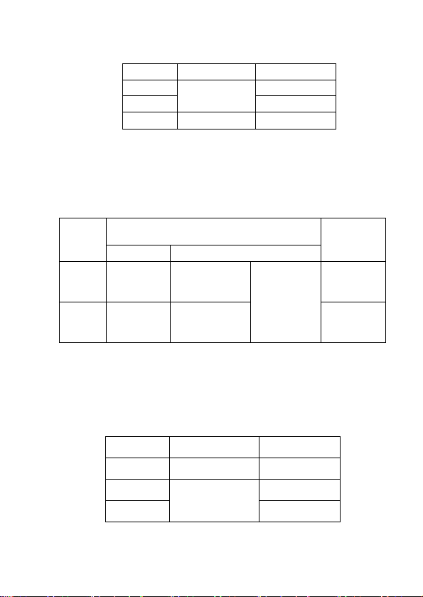
2.2.1 DCV
RANGE
ACCURACY
RESOLUTION
200mV
±(0.5%+3)
100uV
2V
1mV
20V
10mV
200V
100mV
600V
±(1.0%+10)
1V
Input resistance: All ranges: 10 MΩ
Overload protection: 250V DV or AC peak value at 200mV range.
600V DC or AC peak value at other ranges.
2.2.2 ACV True RMS measurement
Range
Accuracy
Resolution
40Hz-200Hz
200Hz-1kHz
2v
±(0.8%+5)
±(0.8%+5) sine
and triangular
wave
±(8.0%+15)
other wave
1mV
200v
100mV
600V
±(1.2%+10)
±(1.2%+10) sine
and triangular
wave
1V
Input impedance:All ranges 10MΩ
Overload protection:250V DC or AC peak value at 200mV , 600V
DC or AC peak value at other ranges.
Frequency response: 40Hz-1kHz
3
Display: True RMS
2.2.3 DCA
RANGE
ACCURACY
RESOLUTION
20mA
±(1.2%+8)
10uA
200mA
100uA
10A
±(2.0%+5)
10mA
Max. input volt drop: 200mV;
Max. input current: 10A(the test time should be within 10 seconds
)
Overload protection: 0.2A/250V fast-blow fuse, no protection at
10A.
2.2.4 ACA True RMS measurement
Range
Accuracy
Resolution
40Hz-200Hz
200Hz-1kHz
200mA
±(1.5%+15)
±(1.5%+15) sine
and triangular
wave
±(8.0%+15)
other wave
100uA
10A
±(3.0%+10)
±(3.0%+10) sine
and triangular
wave
10mA
Max. measuring voltage drop:200mV.
Max. input current: 10A (less than 10 seconds).
Overload protection:0.2A/250V fuse;no protection at 10A.
Frequency response: 40Hz-1kHz.
Display:True RMS
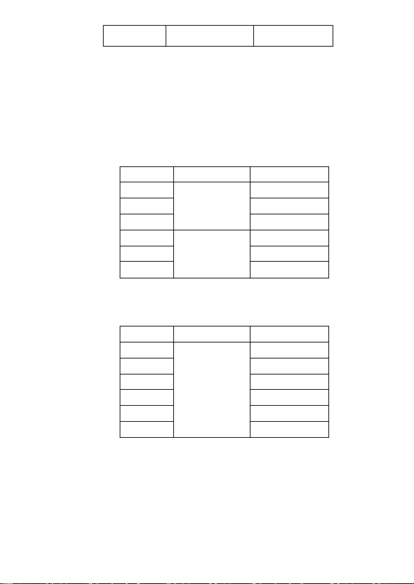
2.2.5 RESISTANCE(Ω)
RANGE
ACCURACY
RESOLUTION
200Ω
±(0.8%+5)
0.1Ω
20kΩ
±(0.8%+3)
10Ω
200kΩ
100Ω
4
20MΩ
±(1.0%+25)
10kΩ
Open voltage: less than 3V.
Overload protection: 250V DC or AC peak value.
NOTE:
1. At 200Ωrange, the test leads should be short-circuited,
and measure the lead to lead resistance, then, subtract from the
real measurement.
2. It is normal for reading to be slow when measured value
is above 1MΩ, please read it after the display value stabilizes.
2.2.6 CAPACITANCE (C)
RANGE
ACCURACY
RESOLUTION
20nF
±(3.5%+20)
10pF
200nF
100pF
2uF
1nF
20uF
±(5.0%+10)
10nF
200uF
100nF
2000uF
1uF
Overload protection: 250V DC or AC peak value
NOTE: when over range, it can keep on measuring, "OL" will not
show on LCD and the value is for reference only
2.2.7 FREQUENCY
RANGE
ACCURACY
RESOLUTION
10Hz
±(1.0%+10)
0.001Hz
100Hz
0.01Hz
1kHz
0.1Hz
10kHz
1Hz
100kHz
10Hz
2MHz
100Hz
Input sensivity:1V RMS , overload protection : 250V DC or AC
peak value(less than 15 seconds)
NOTE: when over range, it can keep on measuring, "OL" will not
show on LCD and the value is for reference only
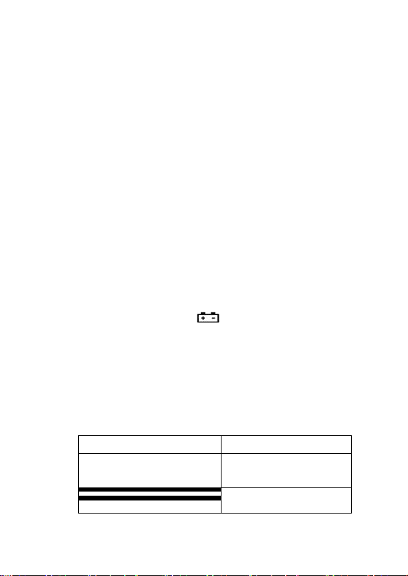
2.2.8 DIODE AND CONTINUITY TEST
5
Range
Displaying value
Test condition
Positive voltage
drop of diode
The positive DC
current is approx.
1mA,negative voltage
is approx. 3V
Buzzer sounds ,
the resistance is
less than(50±20)Ω
open voltage is approx.
3V
Overload protection: 250V DC or AC peak value
Warning: DO NOT input any voltage at this range for safety!
3 OPERATION
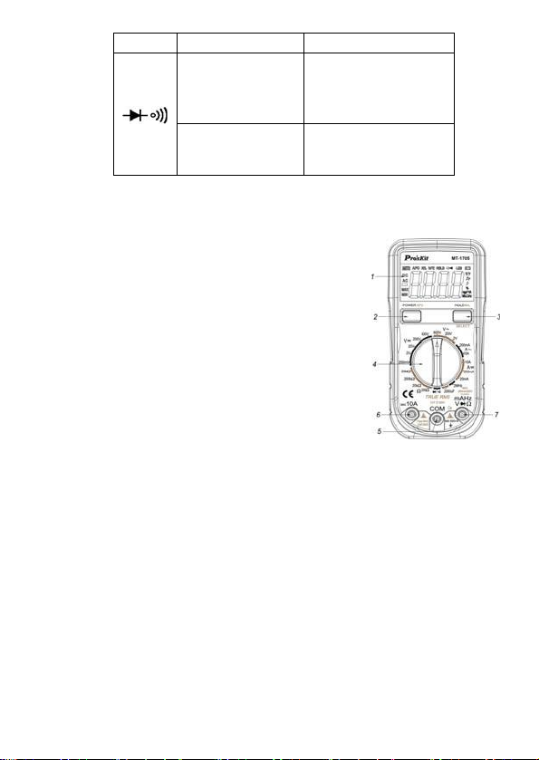
3.1 Front panel description
3.1.1 LCD: display the measured value.
3.1.2 Power/auto power off key: turn on/off
the power and auto power off.
3.1.3 Hold/backlight/function selecting key:
turn on/off hold and backlight key.
3.1.4 Range knob: selecting measuring
function and range .
3.1.5 GND.
3.1.6 10A current test jack.
3.1.7 “+” pole jack of voltage 、resistance、
diode、capacitance and resistance.
3.2 VOLTAGE MEASUREMENT
3.2.1 Insert the black test lead to “COM” jack, the red one to V/Ω/Hz jack.
3.2.2 Set the range knob to a proper DCV/ACV range, If the measured
voltage is unsure beforehand, set the range knob to the highest
range, then reduce it gradually until get the highest resolution
readings.
3.2.3 Apply the test leads to the test point ,the LCD displays the
measured voltage value.
NOTE:
a. If LCD displays “OL”, it means over range, set the range knob to a
higher range.
b. Do not input a voltage over 600V DCA or 600V ACV, the test leads
should be off the test point when switching the function and range.
c. Do not touch a high voltage circuit when measuring high voltage .

6
3.3 CURRENT MEASUREMENT
3.3.1 Insert the black test lead into “COM” jack, the red one to “mA” or
“10A”jack.
3.3.2 Set the range knob to a proper DC or AC mA/A range, If the
measured voltage is unsure beforehand, set the range knob to the
highest range, then reduce it gradually until get the highest
resolution readings.
3.3.3 Connect the test leads to the circuit under test, the LCD displays
the measured voltage value.
NOTE:
a. If LCD displays “OL”, it means over range, set the range knob to a
higher range.
b. When measuring current, mA hole should not exceed 200mA,10A
hole should not exceed 10A(test time should be less than 10 sec.)
3.4 RESISTANCE MEASUREMENT
3.4.1 Insert the black test lead to “COM” jack and the red one to “V/Ω/Hz”
jack.
3.4.2 Set the range knob to a proper resistance range, connect the test
leads across to the resistance being measured.
NOTE:
a. If the resistance value being measured exceeds the max value of
the range selected, LCD displays "OL", , set the range knob to a
higher range. When the resistance is over 1MΩ, the meter may take
a few seconds to stabilize. This is normal for high resistance
readings.
b. When input terminal is in open circuit, overload displays.
c. When measuring in-line resistance, be sure that power is off and all
capacitors are discharged completely.
d. Do not input any voltage at this range.
3.5 CAPACITANCE MEASUREMENT
3.5.1 .Insert the red test lead to “V/Ω/Hz” terminal and the black one to
“COM” jack.
3.5.2 Set the range knob to a proper capacitance range, connect the test
leads to the capacitor being measured(note: the polarity of red
test lead is “+”).
NOTE:
a. If the resistance value being measured exceeds the max value of
the range selected, LCD displays "OL".

7
b. Before measuring, LCD display might not be zero, the residual
reading will decrease gradually and should be disregarded.
c. When measuring large capacitance, LCD may display an unstable
value due to creepage or breaking.
d. Discharge all capacitors completely before capacitance
measurement to avoid damage.
e. Do not input any volt at this range.
f. This range is for automatic range test, measuring the range from
10nF to 2000uF.
g. UNIT: 1mF=1000uF 1uF =1000nF 1nF=1000pF
3.6 FREQUENCY MEASUREMENT
3.6.1 Apply the test lead or shield to cable to “COM” or ““V/Ω/Hz”
terminal.
3.6.2 Switch the knob to frequency range, and connect the test leads
across the signal source or the measured load.
NOTE:
a. When input is 10Vrms or less, a reading is possible but maybe over-
range.
b. Shielded cable is recommended when measuring small signals
under noisy conditions.
c. Be careful when measuring high volt circuit.
d. Do not input a voltage over DC 250V or AC peak factor to avoid
damage to the meter.
e. This range is for automatic range test, Measuring the range from
10Hz to 2MHz
3.7 DIODE AND CONTINUITY TEST
3.7.1 Insert the black test lead to “COM” terminal and the red one to
“V/Ω/Hz” jack( Note: the polarity of red test lead is“+”).
3.7.2 Set the range knob to“ ”range, connect the test leads to the
diode being measured, reading is the approximation of the diode
positive volt drop.
3.7.3 Connect the test leads to two points of the measured circuit, if
buzzer sounds, the resistance is lower than approx.(50±20)Ω.
3.8 DATA HOLD
Press the “HOLD/BL”, LCD displays “HOLD”, the present value is held on
LCD, press it again, the function is cancelled.
3.9 AUTO POWER-OFF
8
After not working about 15minutes, the meter will be changed to sleep
mode. Press “POWER APO” key for 2 seconds to restart the power.
Press the “POWER APO” key for 2 seconds to cancel the function of auto
power off and “APO” icon will disappear from LCD; press it again for 2
seconds to restart the auto power off function and “APO” appears on
LCD.
3.10 POWER ON/OFF
Press “POWER APO” key for 2 seconds to turn on the power and the
meter is in working mode, Press “POWER APO” key again to turn it off.
3.11 BACKLIGHT INDICATION
Press “POWER BL” key to turn on the backlight; press it again to turn off.
If the meter stops working more than 15sec, the backlight will auto power
off.
4 MAINTENANCE
DO NOT tamper with the circuit it’s a precision meter and should only be serviced
by factory personnel.
4.1 Do not operate or store the instrument in high temperature or high
humidity place and do not work closed to flammability substance or
explosive or strong magnetic field.
4.2 Use the damp cloth and soft solvent to clean the meter, do not use
abrasive and alcohol.
4.3 If not operated for a long time, take out the battery.
4.3.1 When LCD displays “ ” symbol, replace the battery as below:
4.3.1.1 Take out of the holster and drop out the battery case.
4.3.1.2 Take out the battery and replace a new one. It’s better to
use alkaline battery for long time use.
4.3.1.3 Fix the battery case and replace the holster.
4.3.2 Replacing fuse
Please use the same type and specification fuse as replacement.
5 TROUBLE SHOOTING
If the meter does not work properly, check the meter as follows:
CONDITIONS
WAY TO SOLVE
NO DISPLAYING
●Power is off
●Replace battery
symbol displays
●Replace battery

Table of contents


