RESISTANCE
Maximum allowable voltage with open circuit: 2,8V
DIODE / TRANSISTOR MEASURING
Approximately voltage in direct way, test short / open and good / faulty
Test voltage: 2,8 Vcc
Test current: 1,5 mA MAX.
Measurements hFE to value transistors (NPN or PNP)
MEASUREMENT METHOD
DC / AC MEASURING
1.- Set the range switch to DC ( ) or AC (V~).
2.- Plug the black testing lead to COM jack and the red testing lead to V,
mA jack.
3.- Touch the tips of the test leads to the measurement points and read the
display.
DC MEASURING ( )
1.- Set the range switch to DCA ( ).
2.- Plug the black testing lead to COM jack.
3.- Plug the red testing lead to V Ohms, mA jack.
4.- Touch the tips of the test leads to the measurement points and read the
display.
RESISTANCE MEASURING
1.- Set the range switch to Ohms.
2.- Connect the black test leading to the COM jack and the red test lead to
red testing lead to V Ohms, mA jack.
3.- Touch the tips of the test leads to the measurement points and read the
display.
DIODE MEASURING
1.- Set the range switch to
2.- Connect the black test leading to the COM jack and the red test lead to
red testing lead to V, mA jack.
3.- Touch the tips of the test leads to the diode. Normally, the voltage drop
of a good diode is around 500 mV to 900 mV. If the diode under test is
faulty, 000 (short-circuit) or 1 (do not conduct).
Shift the diode polarity
hFE VERIFICATION
1.- Set the range switch to hFE.
2.- Insert the emitter pins, base and the transistor gatherer into the
receptacles E, B, C, respectively.
3.- Read the value on the display. The value is the transistor gain, between
0 to 1999.
FUSE REPLACEMENT
CAUTION
Before to remove the battery or replace it, unplug the testing leads from
the energized circuit to prevent a shock hazard.
Usually you don't need to change the fuse, only if the user made a
mistake.
To replace the battery and the fuse (0,2 A / 250 V), remove the screws
located in the back of the cover and open it. Replace the battery with a
new one, check the polarity.
RESISTENCIA
Voltaje máximo a circuito abierto : 2,8 V
PRUEBA DE DIODO Y TRANSISTOR
Voltaje aproximado en sentido directo, prueba corto /abierto y bueno /
defectuoso.
Voltaje de prueba: 2,8 V
Corriente de prueba: 1,5 mA MAX.
Mediciones hFE para valorar transistores (NPN o PNP)
MÉTODO DE MEDICIÓN
MEDICIÓN DE DC (V ), AC (V~)
1.- Ajuste el interruptor de rango a la posición requerida DC (Vcc) o AC
(V~).
2.- Conecte la terminal de prueba negra a la terminal COM y la roja a la
terminal V, mA.
3.- Conecte las terminales de prueba a los puntos de medición y lea el
valor en la pantalla.
MEDICIÓN DE DC (A )
1.- Ajuste el interruptor de rango a la posición requerida DCA (A ).
2.- Conecte la terminal de prueba negra a la terminal COM.
3.- Conecte la terminal de prueba roja a la terminal V Ohms, mA.
4.- Conecte las puntas de prueba a los puntos de medición y lea el valor
en la pantalla.
MEDICIÓN DE RESISTENCIA
1.- Ajuste el interruptor a la posición requerida Ohms.
2.- Conecte la terminal de prueba negra a la terminal COM y la roja a la
terminal V, Ohms, mA.
3.- Conecte las terminales a los puntos de prueba y lea el valor en la
pantalla.
VERIFICACIÓN DE DIODO
1.- Ajuste el selector de rango a la posición
2.- Conecte a la terminal de prueba negra a la terminal COM y la roja a la
terminal V, mA.
3.- Conecte las terminales de prueba al diodo. Normalmente, la caída del
voltaje en sentido directo de un diodo de silicio bueno está alrededor de
500 mV a 900 mV. Si el diodo bajo prueba está defectuosos, 000 (corto
circuito) o 1 (no conduce).
Invierta la polaridad del diodo.
VERIFICACIÓN hFE
1.- Ajuste el interruptor de rango a la posición hFE.
2.- Inserte los alfileres del emisor, base y colector del transistor en los
receptáculos para afilar E, B, C, respectivamente.
3.- Lea el valor presentado de la ganancia del transistor, entre 0 a 1999.
REEMPLAZO DE FUSIBLE
PRECAUCIONES
Antes de intentar remover la batería o reemplazarla, desconecte las
terminales de prueba de algún circuito energizado para prevenir una
descarga eléctrica.
Raramente es necesario cambiar el fusible y se dañará como resultado de
un error del operador.
Para reemplazar la batería y fusible (0,2 A / 250 V) remueva los dos
tornillos de la cubierta posterior. Simplemente cambie la batería vieja y
reemplace por una nueva, teniendo cuidado de observar la polaridad.
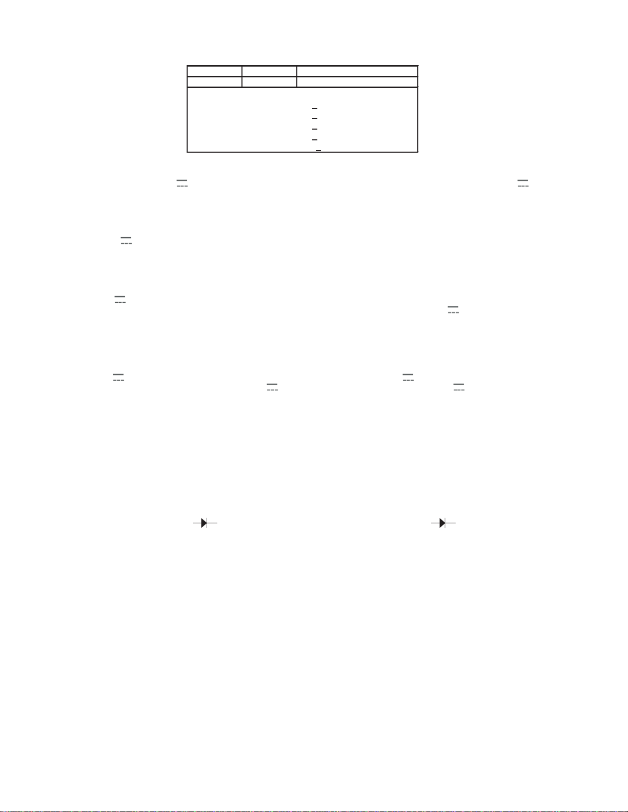
Rango Resolución Precisión
Range Resolution Precision
200 ohms 0,1 ohm + (0,8 % de/of rdg + 2d)
2000 ohms 1 ohm + (0,8 % de/of rdg + 2d)
20 kohms 10 ohm + (0,8 % de/of rdg + 2d)
200 kohms 100 ohm + (0,8 % de/of rdg + 2d)
2000 kohms 1 kohm + (1 % de/of rdg + 2d)