Prology DVD520R User manual

CarAudio
Page
TABLEOFCONTENTS
TechnicalSpecifications....................................................1-2
Measurementsetup....................................................1-3
ServiceAids,SafetyInstruction,etc....................1-4to1-5
Preparations&Controls.....................................1-6to1-8
Maintenance&Troubleshooting..................................1-9
DisassemblyInstructions&Servicepositions..................2
SetBlockdiagram.........................................................3
SetWiringdiagram........................................................4
KeyBoard.....................................................................5
ServoBoard..................................................................6
MainBoard...................................................................7
SetMechanicalExplodedview&partslist........................8
......
......
............
......
......
......
......
......
............
DVD520R

SPECIFICATIONS 1-2
Note:Specificationsanddesignaresubjecttochange
withoutnoticeforproductimprovements.
FMStereoRadio
Frequencyrange:87.5-108.0Mhz(EUROPEMODE)
87.5-107.9Mhz(USAMODE)
65.0-74.0MHz(OIRTMODE)
Usablesensitivity:
Frequencyresponse:
Stereoseparation:
Imageresponseratio:
IFresponseratio:
Signal/noiseratio
8dB
30Hz-15kHz
30dB(1kHz)
50dB
70dB
>55dB
Components
Mountingcollar
TappingscrewsM5x6mm4
M4x6mm4
Mountingbolt(50mm)1
Wireconnector
Removablefaceplatecase
Trimplate1
T-key2
OperatingInstructions1
Rubber
Remotecontroller
cushion1
1
1
1
1
General
Powersupply:
Maximumpoweroutput:
Continuouspoweroutput:
Suitablespeakerimpedance:
Pre-Ampoutputvoltage:
12VDC(11V-16V)
Testvoltage14.4V,negativeground
55Wx4channels
25Wx4channels(410%T.H.D.)
4-8ohm
4.0V(CDplaymode:1KHz,0dB,10Kload)
Fuse:
Dimensions(WxHxD)
Weight:
15A
178x50x166mm
1.7kg
Aux-inlevel: ≥300mV
4.0V
Sub-out:
DiscPlayer
System:
Frequencyresponse:
Signal/noiseratio:
Totalharmonicdistortion:
Discdigitalaudiosystem
20Hz-20kHz
>80dB
Lessthan0.20%(1kHz)
Video:
videooutput:
horizontalnesowtiou: 10.2V
500lines
≥
Videosignalformatsystem: PAL/NTSC

MEASUREMENTSETUP
TunerFM
DUT
RFGenerator
Bandpass LFVoltmeter
e.g.PM5326
250Hz-15kHz
e.g.712270748001 e.g.PM2534
S/Nanddistortionmeter
e.g.SoundTechnologyST1700B
Useabandpassfiltertoeliminatehum(50Hz,100Hz)anddisturbancefromthepilottone(19kHz,38kHz).
TunerAM(MW,LW)
DUT
RFGenerator
Bandpass LFVoltmeter
e.g.PM5326
250Hz-15kHz
e.g.712270748001 e.g.PM2534
S/Nanddistortionmeter
e.g.SoundTechnologyST1700B
Frameaerial
e.g.712270789001
ToavoidatmosphericinterferenceallAM-measurementshavetobecarriedoutinaFaradayscage.
Useabandpassfilter(oratleastahighpassfilterwith250Hz)toeliminatehum(50Hz,100Hz).
'
DUT L
R
LEVELMETER
e.g.SennheiserUPM550
withFF-filter
S/Nanddistortionmeter
e.g.SoundTechnologyST1700B
UseAudioSignalDiscSBC429482239730184
(replacestestdisc3)
CD
1-3

1-4
SOLDER
CHIP
COMPONENT
GLUE
SOLDER
COPPERTRACK
P.C.B
SERVICEPACKAGE
GENERAL DISMOUNTING MOUNTING
SOLDERING
IRON
VACUUMPISTON
482239510082
e.g.WELLER
SoldertipPT-H7
SOLDERING
IRON
SOLDERWICK
482232140042
e.g.APAIROFTWEEZERS
HEATINGHEATING
SOLDERING
IRON
SOLDERWICK CLEANING
PRECAUTIONS
COPPERTRACK
IRON
CORRECT
SOLDERING
IRON
SOLDERING
CHIPCOMPONENT
EXAMPLES
CORRECT
IRON
SOLDERING
NO!
e.g.APAIROFTWEEZERS
SLODERING
IRON
SLODER
SLODERINGTIME
SLODERING
IRON
Φ0.5-0.8mm
<3secretary/side
PRESSURE
PRESSURE
SOLDER
Φ0.5-0.8mm
A
B
C
B
A
HANDLINGCHIPCOMPONENTS

WARNING
GB
AllICsandmanyothersemi-conductorsare
susceptibletoelectrostaticdischarges(ESD).
Carelesshandlingduringrepaircanreducelife
drastically.
Whenrepairing,makesurethatyouare
connectedwiththesamepotentialasthemass
ofthesetviaawristwrapwithresistance.
Keepcomponentsandtoolsalsoatthis
potential.
CLASS1
LASERPRODUCT
ATTENTIONGB
Safetyregulationsrequirethatthesetberestoredtoitsoriginal
conditionandthatpartswhichareidenticalwiththosespecified,
beused.
1-5
ATTENTION
TouslesICetbeaucoupd'autres
semi-conducteurssontsensiblesaux
dechargesstatiques(ESD).
Leurlongevitepourraitetreconsiderablement
ecourteeparlefaitqu'aucuneprecautionn'est
prisealeurmanipulation.
Lorsdereparations,s'assurerdebienetrerelie
aumemepotentielquelamassedel'appareilet
enfilerlebraceletsertid'uneresistancede
securite.
Veilleracequelescomposantsainsiqueles
outilsquel'onutilisesoientegalementace
potentiel.
WARNING
D
AlleICsundvieleandereHalbleitersind
empfindichgegenuberelektrostatischen
Entladungen(ESD).
UnsorgfaltigeBehandlungimReparaturfallkan
dieLebensdauerdrastischreduzieren.
VeranlassenSie,dassSieimReparaturfalluber
einPulsarmbandmitWiderstandverbunden
sindmitdemgleichenPotentialwiedieMasse
desGerates.
BauteileundHilfsmittelauchaufdiesesgleiche
Potentialhalten.
F
ESD NL
I
WAARSCHUWING
AlleIC'senveleanderehalfgeleiderszijn
gevoeligvoorelectrostatischeontladingen
(ESD).
Onzorgvuldigbehandelentijdensreparatiekan
delevensduurdrastischdoenverminderen.
Zorgervoordatutijdensreparatieviaeen
polsbandmetweerstandverbondenbentmet
hetzelfdepotentiaalalsdemassavanhet
apparaat.
Houdcomponentenenhulpmiddelenookop
ditzelfdepotentiaal.
AVVERTIMENTO
TuttiICeparecchisemi-conduttorisono
sensibiliallescarichestatiche(ESD).
Lalorolongevitapotrebbeesserefortemente
ridattaincasodinonosservazionedellapiu
grandecauzioneallaloromanipolazione.
Duranteleriparazionioccorrequindiessere
collegatoallostessopotenzialechequellodella
massadell'apparecchiotramiteunbraccialetto
aresistenza.
Assicurarsicheicomponentieanchegliutensili
conqualisilavorasianoancheaquesto
potenziale.
Pourvotresecurite,cesdocuments
doiventetreutilisespardesspecia-
listesagrees,seulshabilitesareparer
votreappareilenpanne.
NL
F
D
I
DK
SF
S
GB
Veiligheidsbepalingenvereisen,dathetapparaatbijreparatiein
zijnoorspronkelijketoestandwordtteruggebrachtendatonderdelen,
identiekaandegespecificeerde,wordentoegepast.
Afterservicingandbeforereturningsettocustomerperforma
leakagecurrentmeasurementtestfromallexposedmetalpartsto
earthgroundtoassurenoshockhazardexist.Theleakagecurrent
mustnotexceed0.5mA.
LenormedisicurezzaesigonocheI'apparecchiovengarimesso
nellecondizionioriginaliechesianoutilizzatiipezzidiricambio
identiciaquellispecificati.
Warning!
Varning!
Varoitus!
Advarse!
Invisiblelaserradiationwhenopen.
Avoiddirectexposuretobeam.
312211003420
Avatussalaitteessajasuojalukituksenohitettaessaoletalttiina
nakymattomallelaserisateilylle.Alakatsosateeseen!
Usynliglaserstrlingvedabningnarsikkerhedsafbrydereer
udeaffunktion.Undgaudsaettelseforstraling.
a
BeijederReparatursinddiegeltendenSicherheitsvorschriftenzu
beachten.DerOriginalzustanddesGeratsdarfnichtverandertwerden;
furReparaturensindOriginal-Ersatzteilezuverwenden.
LesnormesdesecuriteexigentqueI'appareilsoitremisaI'etat
d'origineetquesoientutiliseeslespiecesderechangeidentiques
acellesspecifiees.
Osynliglaserstralningnarapparatenaroppnadochsparren
arurkopplad.Betraktaejstralen.

PREPARATIONS 1-6
WiringDiagram
UsingtheISOConnector
ConnectorConnector
2.ForconnectionswithouttheISOconnectors,checkthewiringinthevehiclecarefully
Cuttheconnector,connectthecoloredleadsofthepowercordtothecarbattery,
beforeconnecting,
incorrectconnectionmaycauseseriousdamagetothisunit. asshowninthecolour
codetablebelowforspeakerandpowercableconnections
1.IfyourcarisequippedwiththeISOconnector,thenconnecttheISOconnectorsasillustrated.
FilterBox
Aux-in(Black)
Subwooferout (Green)
GroundLead
LeftSpeaker
(Front) LeftSpeaker
(Rear)
RightSpeaker
(Front)
RightSpeaker
()Rear
White/
Black
Stripe
WhiteGray/
Black
Stripe
Green/
Black
Stripe
GrayGreenPurple/
Black
Stripe
Purple
Black
Blue Motor/ElectricAntennarelaycontrolLead
AmplifierrelaycontrolLead
ISOConnector
Connector
Originalwiring
Modifiedwiring
Red
Yellow Yellow
Red
Red
YellowYellow
Red
Antenna
Fuse15A
R(Red)
L(White)
()Yellow
RearLine-out(Gray)
R(Red)
L(White)
FrontLine-out(Brown)
Amplifier
ForsomeVW/AudiorOpel(Vauxhall)
carmodels,youmayneedtomodify
wiringofthesuppliedpowercordas
illustrated,orelsethememoryofthe
unitmaybelostafteryoupoweroff.
Contactyourauthorizedcardealer
beforeinstallingthisunit.
Ignitionkey
+12VDCWhenON/ACC
Tocarbattery(+)
Continuous+12VDC
Yellow
Red
Video-out
R(Red)
L(White)

1-7
CONTROLS
Poweron:pressanybuttononthepanelexcepttoturnontheunit.
Pressthebuttontoopenthepanelandpresstoejectthedisc.
DiscEject Discslot:insertadiscforplaybackhere.
RESETHOLE
Note:
PressingtheRESETholewillerase
theclocksettingandstoredstations.
Panelstatusindicator:
Lightsupwhenyouslidethepaneldown;
Flasheswhenyouremovethepanel.
Tofastsearchwithin
atrack/skiptonext
orprevioustrack
VOL
DN
UP
INT RPT RDM
AMS
BAND
6
5
4
3
2
MUTE
1
DISP
SRC
PWR
Radiotune
PresstotuneinapresetstationHoldfor
morethan2secondstostorestation.
Radiopreset
PanelOpen
AMS
FM(OIRT)
FM1
FM2
FM3
PowerON/OFF
Displayswitch
Radio
Discplay
(whendiscisin)
Remotesensor
Aux-in
AlternativeFrequency
regionON/OFF
TrafficAnnouncements
Identification
ProgramType
Rotatetheknobto
adjustvolumelevel
PushtoselectVOL/BAS/
TRE/BAL/FAD,Rotatethe
knobtoadjustlevel
Pushmorethan2seconds
toMenumode

1-8
PowerOn:Pressanybuttonontheremotecontroltoturnontheunit.
2.Insertthebutton-typelithiumbatterywiththe
markfacingupward. (+)
Insertthebatteryholderintothe
remotecontrol.
1.Pulloutthebatteryholderwhilepressingthestopper.
Replacingthelithiumbatteryofremotecontrolunit.
*Whentheoperationrangeofthecardremote
controlbecomesshortornoProperly,replace
thelithiumbatterywithanewone.Makesure
thebatterypolarityreplacementiscorrect.
(CR2025)
WARNINGS:
REMOTECONTROLS
Storethebatteryinplacewherechildrencannotreach.
Ifachildaccidentallyswallowsthebattery,
consultadoctorimmediately.
Donotrecharge,short,disassembleorheatthebattery
ordisposeitinafire.
Doinganyofthesethingsmaycausethebatterytogive
offheat,crackorstartafire.
Donotleavethebatterywithothermetallicmaterials.
Doingthismaycausethebatterytogiveoffheat,crack
orstartafire.
Whenthrowingawayorsavingthebattery,wrapitintape
andinsulate;otherwise,thebatterymaystarttogiveoff
heat,crackorstartafire.
Donotpokethebatterywithtweezersorsimilartools.
Doingthismaycausethebatterytogiveoffheat,crack
orstartafire.
1
ABC 2
DEF 3
GHI
4
JKL 5
MNO
7
TUV 8
WXYZ
9
SPACE
6
PQRS
010+
+-_
MUTE
REPEAT
OSD
BAND
P/N
TITLEZOOM
SUB.T
DISP
PBC
MENU
SETUP
ENTER
ANGLE
SLOW
AUDIO
SRC
VOL+
SEL
VOL
-
SEEK+
-
SEEK
Discplay/pause
SEL(ect)toselectbasic
settingoptionssound
Vol/Bas/Tre/Bal/Fad
Mute
Volume
Tofastsearchwithin
atrack/skiptonext
orprevioustrack
RadioTune
Stop/Return
Slowlyplayback1/32,1/16,1/8,1/4,1/2
PBC(forVCD2.0orgreater)
Displaycurrentlocation
Poweron/off
DVDSetup
Enter
DigitArea
TrickModes
DiscPlay
(whendiscinserted)
Radio
Aux-in
REPEAT:Title\chapter\disk\track\index
A-Brepeatedly
ONScreendisplay
PressTitle
SelectSubtitleLanguage(onlyDVD)
SelectCameraAngle(onlyDVD)
SelectAudioTrack(language)(onlyDVD)
DirectionalButtons
forMenuSelections
VideomodePAL/NTSC/AUTO
Radioband
PROG
MENU
Program
AB

Troubleshooting
Ifyoususpectsomethingiswrong, immediatelyswitchpoweroff.Immediatelystopusingitandcallthestorewhereyoupurchasedit.
Nevertrytorepairtheunityourselfbecauseitisdangeroustodoso.
Whenadiscbecomesdirtycleanitwithacleaningcloth.
Wipethediscfromthecenterout.
Afterprolongeduse,dirtordustmayaccumulateatthelens.Toensuregoodplaybackquality,cleanthediscwithPhilipsCDlens
Cleaneroranycommerciallyavailablecleaner.Followtheinstructionssuppliedwithcleaner.
Toensuregoodplaybackquality,cleantheheadsA,thecapstanB,
andpressurerollerCafterevery50hoursoftapeoperation.Used
acottonswabslightlymoistenedwithcleaningfluidoralcohol.
Youcanalsocleantheheadsbyplayingacleaningtapeonce.
Clearingdisc
Cleaningthedisclens
CleaningtheheadsandtheTapeParts
Maintenance
MAINTENANCEANDTROUBLESHOOTING
1-9
General Radio
Disc
Discisupsidedown.
Discisdirtyordamaged
Placediscinthecorrectdirection,
andthelabelsideup.
Cleandiscorchangeanotherdisc.
Discisinsidebut
nosound.
Discsoundskips,
tonequalityislow. Discisdirtyordamaged.
CleanCDorchangeanotherCD.
Muchnoisein
broadcasts Stationistoofar,orsignalsaretooweak.
Selectotherstationsofhighersignallevel.
Batterycableisnotcorrectlyconnected.
Connectthebatterycabletothe
terminalthatisalwayslive.
Presetstation
lost
Mountingangleisover30o.
Adjustmountingangletolessthan30.
o
Soundskipsdue
tovibration. Unstablemounting.
Mounttheunitsecurelywiththe
mountingparts.
Nopoweror
nosound
Car'sengineswitchisnoton.
Cableisnotcorrectlyconnected.
Fuseisburnt.
Iftheabovesolutionscannothelp,
Turnyourcar'skeytoACCorON.
Checkconnection.
Replacefuse.
Checkvolumeormuteon/off.
PresstheRESETbutton.
ErrorDisplayMessages
Discisdirty,damagedorupsidedown.
Presstoejectthedisc.
Nodiscintheunit.
Insertdiscsintotheunit.

2-1
DISMANTLINGINSTRUCTIONS
2-1
R
Remove2pcs
screwonthe
topofloader.
2emovetopandbottomcovers. 4RemoveCDloader
1Pullouttheshortsheetfrommainset.
3Loosen4pcsscrewtoremoveFrontCabinet.
Remove2pcsscrew
fromfrontcabinet.
Loosen8screwsto
removeheatsink&
topcover&bottom
cover.
Removethe2pcs
screwtodismantle
theframe.
Remove6pcs
screwonthe
mainboard.
PulloutFPC
wire.
Removethetwo
connectorsfrom
themainboard.
Removethe2pcs
screwtodismantle
theframe.

2-2
DISMANTLINGINSTRUCTIONS
2-2
ServicePositionA
ServicePositionB
ServicePositionC
ServicePositionD

3
SETBLOCKDIAGRAM
3
ElectricSelector&Volume
TDA7460 Pre-Amp
RC4558
Pre-Amp
RC4558
LCDDisplay
MCU
ST72F321AR9T6
LCDDriver
L6523C
IN1
MUTE
ST-BY
IN2
OUT1+
OUT1-
OUT2+
OUT2-
PW-GND
IN3
IN4
OUT3+
OUT3-
OUT4+
OUT4-
PW-GND
PW-GND
AC-GND SVRTAB S-GND
Vcc1 Vcc2
N.C.
PowerAmplifier
TDA7384
PW-GND
F/L
F/R
R/R
R/L
LCDData
LCDClock
LCDCE
Mute
Line-Output
F/R
F/L
F/L
F/R
R/R
R/L
F/L
F/R
R/R
R/L
DVD-L
DVD-R
CHICK-SW
KIN0-1
EJECT-SW
LOAD-SW
EN
DVD-CLK
XIR
CS
DATA
KV5V-ON
VIDEO-OUT
DVD-R
AUX-R
AUX-L
CDC-R
CDC-L
D5V
GND
PowerSupply
DVD+9V
AP1507
DC11~16V
Ground
D9V
B5V
MCUDC5V
MCUDC5V ACC
DC11~16V
ControlledPower
D5V
SUPPLY
LOUDNESS
DEMODULATOR
+STEREO ADJUST
+STEREOBLEND
CREF
OUTLR
PILOT
CANCELLATION
VS
CASSL
INPUT
MULTIPLEXER
+
AUTOZERO
PHONE GND
(MPOUT)
BEEP
MPX
MIXING
STAGE VOLUMEBASS
TREBLE
OUTLR
OUTLF
OUTRR
OUTRF
OUTLF
OUTRR
OUTRF
SCL
SDA
80KHz
LP
FMR
FML
PLL
25KHz
LP S&H HIGH
CUT
CONTROL
MULTIPATH-
DETECTOR PULSE
FORMER
D
LEVEL
CDLCDGCDR
AM
CASSR
PHONE
(MPIN)
GND
SMUTE
PHONE
SOFT
MUTE
PIL
DET
ICBUS
2
NOISE
BLANKER A
8
1
2
7
6
9
15
1420
3451117
19
16
18
12
13
10
KST-6102
D5V
D9V
AM/FMOUT
TDA7479
GND
SINGLECHIPRDSDEMODULATOR+FILTER
PC7/SS
PA1
PA0
QUADBILATERAL
CD4066BC
AUX/CDC-R
AUX/CDC-L
CDC-ON
SDRAM
M
MotorDriver
BA5954
M3355 VIDEO-OUT
MIC ROM
(TSOP48PIN)
DigitalAudioI/O
Audio
DAC
(2CH~
8CH)
AnalogAudioI/P
M
MIC
WM8728
FLASHMX29LV800T
DigitalAudioI/O
DVD-R
DVD-L
DVD-PLAYER4-IN-1SINGLECHIP
1MX16X4BANK
(TSOP1154PIN)
D9V
Pre-Amp
RC4558
SubOut

44
SETWIRINGDIAGRAM

KEYBOARD
TABLEOFCONTENTS
LCDPINCONNECTION
5-15-1
LCDDisplay..........................................................5-1
Frontboard...........................................................5-2
connectorboard....................................................5-2
KeyBoardCircuitDiagram......................................5-3
KeyBoardLayoutDiagram......................................5-4
ElectricalPartsList.................................................5-5

5-25-2
FRONTBOARD-CIRCUITDIAGRAMCONNECTORBOARD-CIRCUITDIAGRAM
FRONTBOARD-LAYOUTDIAGRAMCONNECTORBOARD-LAYOUTDIAGRAM

5-35-3
KEYBOARD-CIRCUITDIAGRAM

5-45-4
KEYBOARD-LAYOUTDIAGRAM
TOPVIEW
KEYBOARD-LAYOUTDIAGRAM
BOTTOMVIEW

PartNO. Description QTY Location
ELECTRICALPARTSLIST-KEYBOARD
5-55-5
84-DVD705RS-KB04-A
82-CM705-KB02-C
11-0102-0R02-0
11-0102-1022-0
11-0102-1032-0
11-0102-1521-0
11-0102-1811-0
11-0102-2202-0
11-0102-2211-0
11-0102-2222-0
11-0102-3311-0
11-0102-3322-0
11-0102-4711-0
11-0102-4732-0
11-0102-6811-0
11-0103-4711-0
11-0103-6811-0
11-0202-1021-0
11-0203-1051-0
11-0406-0005-A
11-0901-0065-A
11-1821-0594-C
11-2011-0025-0
11-0103-7511-0
11-0102-1012-0
11-0181-0010-A
11-0406-0032-0
11-2602-0030-0
11-3101-0034-0
11-0421-0001-B
DVD705RS-58E
CM705KBSMT
RMF01/16W5%SMT0603
RMF1K1/16W5%SMT0603
RMF10K1/16W5%SMT0603
RMF1K51/16W5%SMT0603
RMF1801/16W5%SMT0603
RMF221/16W5%SMT0603
RMF2201/16W5%SMT0603
RMF2K21/16W5%SMT0603
RMF3301/16W5%SMT0603
RMF3K31/16W5%SMT0603
RMF4701/16W5%SMT0603
RMF47K1/16W5%SMT0603
RMF6801/16W5%SMT0603
RMF4701/10W5%SMT0805
RMF6801/10W5%SMT0805
CC1000PF/50V10%0603(X7R)
CC1F/25V-80%+20%SMT0805
LED2.2V10MAGREENSMT0603
ICPT6523LCDDRIVE
PCBCM705KBD/S1.2MMVER.2
TACTSW250GF4.3MM(SMT)CHIFENGDifeng
RMF7501/10W5%SMT0805
RMF1001/16W5%SMT0603
ECB12(7X5)(PV)S17
LED3.5V25MAWHITE3MM(FCWHWAO-AO)
LCDDVD705NEGATIVECOLOUR(SA)
14PINSOCKETMALEESTF2-14-01
REMOTE-CRMHEADER
±
±
±
±
±
±
±
±
±
±
±
±
±
±
±
±
μ
()
±
±
Φ
1
1
2
2
1
2
2
4
2
1
2
1
2
3
2
10
4
1
3
21
1
1
17
1
1
1
2
1
1
1
R101,R407
R107,R117
R119
R108,R118
R102,R112
R120~R123
R103,R113
R109
R104,R114
R110
R105,R115
R139,R201,R202
R106,R116
R125~R133R141
R134~R137
C101
C102,C103,C104
D101~D121
IC101
SW101~SW117
R140
R145
EN101
D126,D127
LCD101
CON101
IC102
,

6-16-1
SERVOBOARD
TABLEOFCONTENTS
CircuitDiagram.........................................................6-2to6-5
PCBLayout........................................................................6-6
..............................................................6-7ElectricalPartsList

6-26-2
SERVOBOARD-CIRCUITDIAGRAM
Table of contents
Other Prology Car Stereo System manuals
Prology
Prology DVD510 User manual
Prology
Prology CMD-170 User manual
Prology
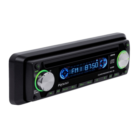
Prology CMD-150 User manual
Prology
Prology CMD-115 User manual
Prology
Prology MDN-2410 User manual

Prology
Prology MCE-525UR User manual
Prology
Prology DVD520 User manual
Prology
Prology DVD525UR User manual
Prology
Prology CMD220 User manual
Prology
Prology DMD170 User manual
Popular Car Stereo System manuals by other brands

Philips
Philips CID3680/93 quick start guide
Blaupunkt
Blaupunkt Antares T60 Operating and installation instructions
Metra Electronics
Metra Electronics 95-8903S installation instructions

Axxera
Axxera AXS609 Installation & owner's manual
JL Audio
JL Audio Stealthbox SB-D-TRKEXT/10W1 installation guide
Pioneer
Pioneer DEH-X3850UI owner's manual

