promelectroavtomat ULT2003D User manual

SERVICE MANUAL FOR
COMPUTERIZED SEWING MACHINE
ULT2003D
SUPER GALAXIE 3100D
ULT2001N
ULT2001C
M3000N
M3000C
3. 2003.
www.promelectroavtomat.ru

This service manual has been compiled for explaining repair procedures of this MODEL.
This was produced based on up-to-date product specifications at the time of issue, but there may have been
changes of specifications for the purpose of improvements.
Contact manufacturer or local sales company for information concerning such changes.
Brother Industries, Ltd.
Nagoya, Japan
I.PRINCIPAL MECHANISMS..................................................................................1
II.DISASSEMBLING AND REASSEMBLING THE SEWING MACHINE................8
III.HOW TO ADJUST MECHANICAL ELEMENTS.................................................24
IV.HOW TO ADJUST ELECTRONIC ELEMENTS.................................................58
1. Always use rubber gloves when handling printed circuit boards and never touch the metal portion of a printed
circuit board with bare hands.
2. Keep your body earthed in order to avoid generating static electricity.
3. Pack printed circuit boards in aluminum foil and avoid subjecting them to any form of impact during storage
or transportation.
4. Do not touch or damage the metal portion of a printed circuit board with a screwdriver or any other tool while
making repairs or the like.
www.promelectroavtomat.ru

-1-
I.
1.MECHANICAL CHART....................................................................................2
2.POWER TRANSMISSION CHART..................................................................3
3.ELECTRONIC PARTS ARRANGEMENT CHART...........................................4
4.CONTROL SYSTEM BLOCK DIAGRAM........................................................5
5.MAIN MOTOR CONTROL................................................................................5
6.PATTERN GENERATOR.................................................................................6
7.AUTOMATIC THREAD TENSION....................................................................6
8.OTHER ELECTRONIC COMPONENT FUNCTIONS......................................7
www.promelectroavtomat.ru
-2-
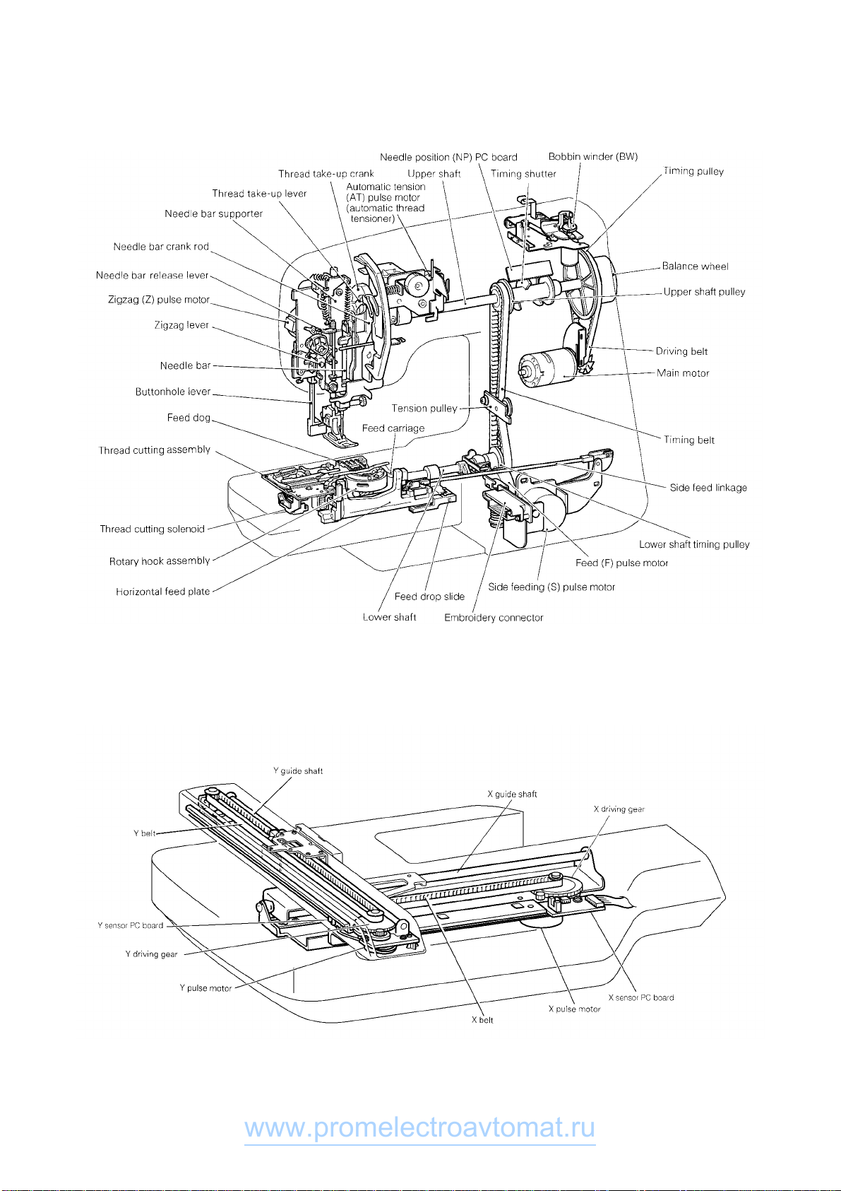
1. MECHANICAL CHART
EMBROIDERY UNIT MECHANISM
www.promelectroavtomat.ru
-3-
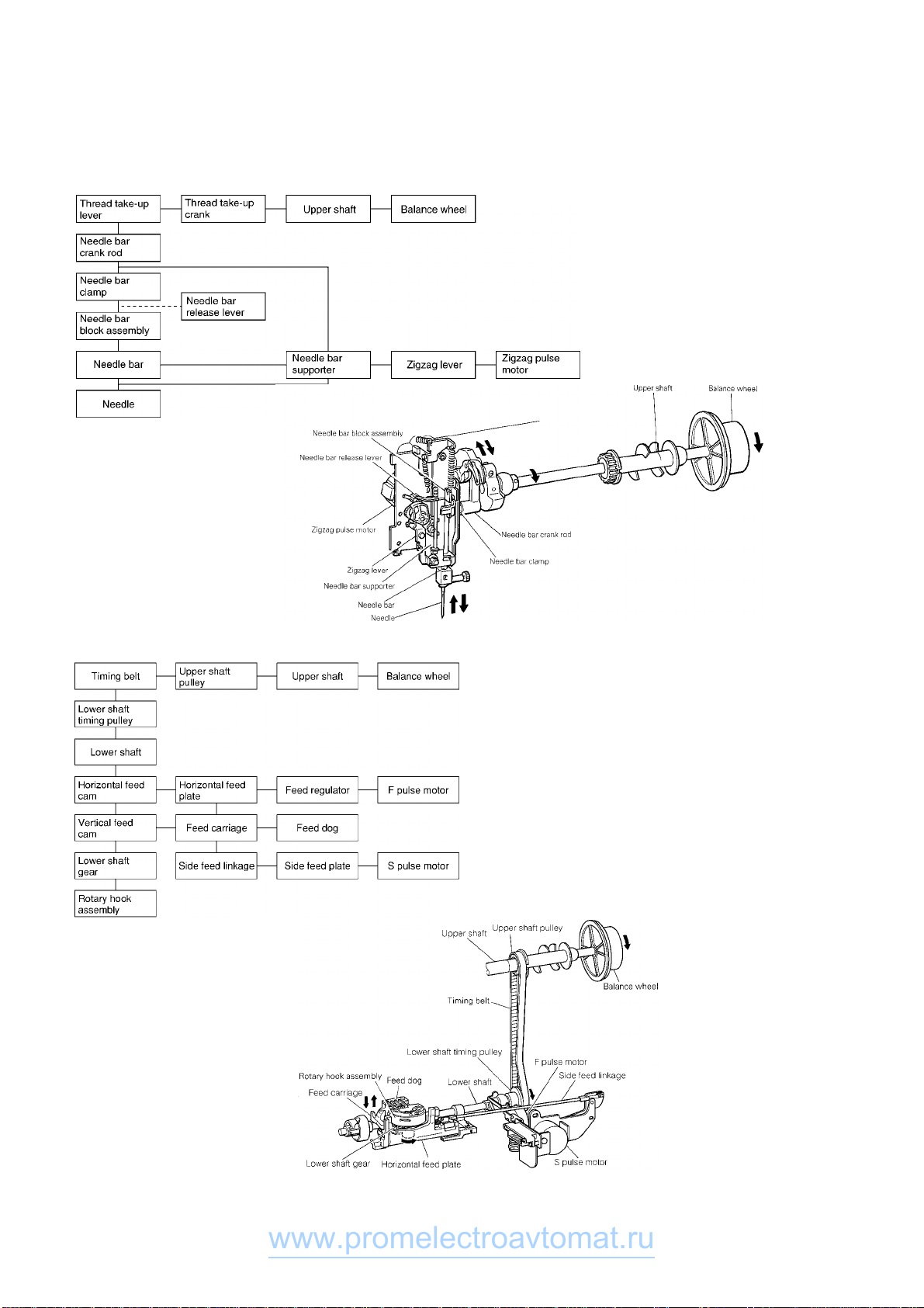
2. POWER TRANSMISSION CHART
(A) Generating mechanism of needle bar, thread take-up lever and zigzag movements
(B) Mechanism of feed dog and rotary hook movement
www.promelectroavtomat.ru
-4-
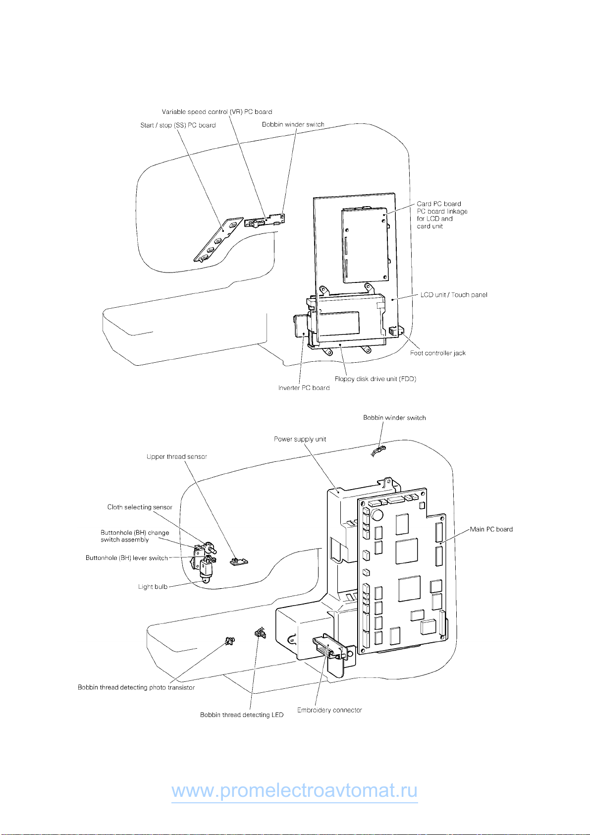
3. ELECTRONIC PARTS ARRANGEMENT CHART
www.promelectroavtomat.ru
-5-
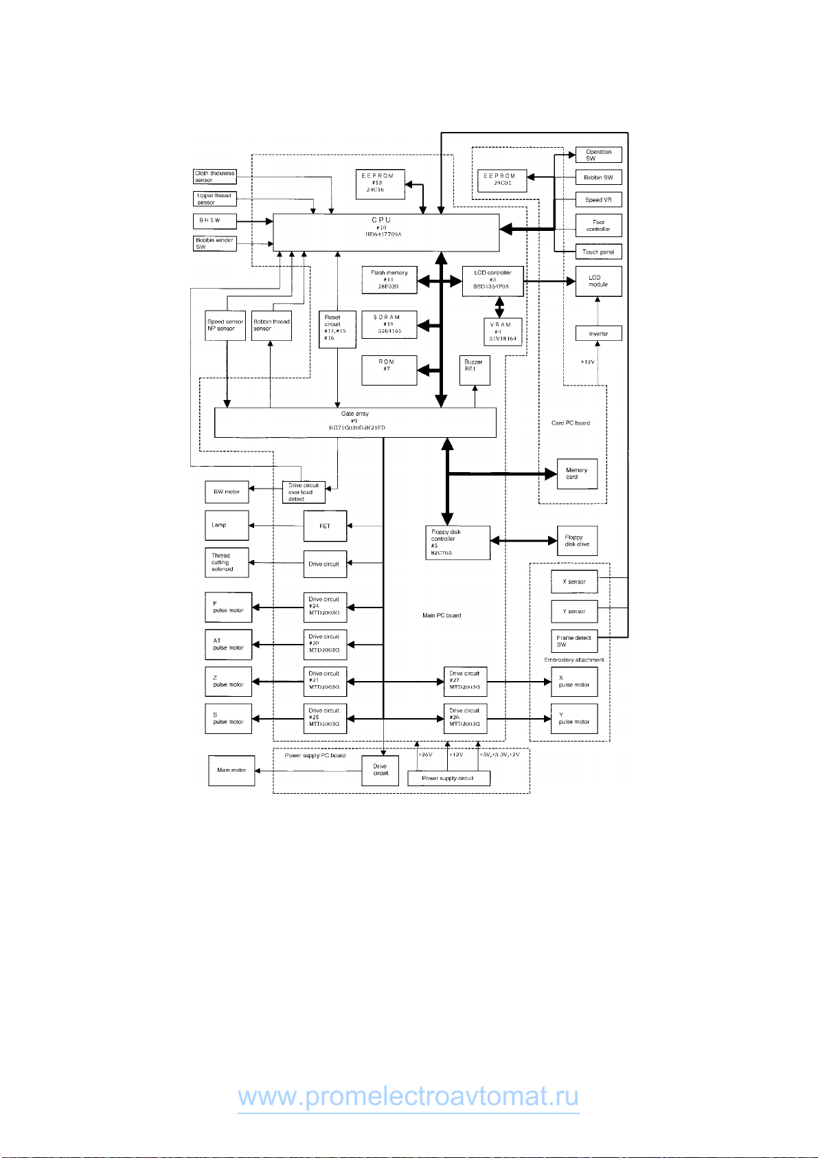
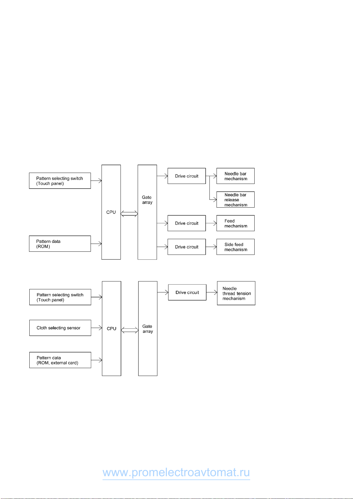
4. CONTROL SYSTEM BLOCK DIAGRAM
5. MAIN MOTOR CONTROL
The main motor for the sewing machine is required to smoothly change from low speed to high speed without any
fluctuations due to load or temperature changes. To fully comply with this requirement this machine adopts Pulse
width modulation (PWM) control using Field Effect Transistor (FET).
www.promelectroavtomat.ru
-6-
6. PATTERN GENERATOR
For conventional sewing machines, the pattern was generated by rocking the needle bar and the feed regulator
by means of a pattern cam onto which the pattern data had been mechanically engraved. In contrast to this, this
model stores the data electronically in memory and uses a feed pulse motor, horizontal pulse motor and a zigzag
pulse motor to directly rock the needle bar and the feed regulator to generate the pattern. As a result of this, it is
possible to increase the number of patterns and the number of stitches simply by adding extra memory capacity,
so that about 3,800 patterns comprising a total of approximately 20,000 stitches can be stored. In addition, the
pulse motors must move the position of the needle while the needle is raised and stop it in the correct position
(and similarly, they must move the position of the feed regulator while the needle is lowered). Thus, highly-
precise positioning and a fast response speed are required. Because of this, the feed pulse motor, horizontal
pulse motor and a zigzag pulse motor were adopted, and a simple open-loop structure circuit structure was
employed.
Block diagram of pattern generator control
7. AUTOMATIC THREAD TENSION BLOCK DIAGRAM
www.promelectroavtomat.ru

-7-
8. OTHER ELECTRONIC COMPONENT FUNCTIONS
Start/stop switch...................................used to start and stop (SS) the machine. If you want to start sewing at low
speed, keep this switch depressed and start sewing.
Backstitch switch..................................used for backstitching and lockstitching. Backstitching is performed at low
speed in the reverse direction while the switch is pressed. For
lockstitching, three stitches are made at the current needle position and
then sewing stops.
Needle position (UP/DOWN) switch.....used to change the needle position either up or down.
Automatic thread cutter switch.............used to cut the thread automatically. When you press this switch, the
machine will automatically cut the thread, regardless of the needle
position, and stop with the needle at its upper position.
Touch panel..........................................used to select pattern and input test mode number required for sewing by
simply touching the display on the panel. This simplifies the operation for
selecting the desired pattern and number.
Buttonhole stitch switch........................used to detect the edges of the buttonhole stitch by means of the
buttonhole stitch presser foot and lever.
Buttonhole stitch lever switch...............used to detect whether the buttonhole stitch lever is raised or lowered.
Speed sensor.......................................used to detect the rotation speed of the main motor. detects the operating
speed of the main motor by means of a photointerruptor and shutter
installed on the upper shaft.
Bobbin winder start stop switch............used to start stop the bobbin winding.
Bobbin winder switch............................used to detect whether the bobbin winder has been set when winding the
lower thread.
Foot controller jack...............................when using the foot controller, connect it to this terminal.
Transformer..........................................used for driving the pulse motors and solenoids, to illuminate the lamps
and to supply power to the electronic circuitry.
Light bulb..............................................is 12V 5W.
www.promelectroavtomat.ru


-9-
1. DISASSEMBLING AND REASSEMBLING THE OUTER PARTS AND MAIN
PARTS
1. Remove the screw securing the face plate, and the face plate by sliding it to the left.
2. Remove the screw securing the free arm cover, and the free arm cover by sliding it to the left.
3. Remove the notch on the right side of the upper cover, and while holding it to the right remove the upper
cover.
4. Remove the one screw on the front thread guard cover, then remove the front thread guard cover.
5. Remove the screw securing the front cover (at back right side of handle), and loosen the two screws (below
jaw section on face plate side, below free arm). Open the front cover toward the front, remove the three
connectors and then the front cover.
(When removing the connectors, always release the lock on the main board connector first.)
(When the front cover has been removed, always adjust the touch panel after assembling the front cover.)
6. Remove the screws at the 4 locations, then remove the FDD unit.
7. Remove the two screws securing the needle plate, and the needle plate.
8. Remove the three screws securing the rear cover, and the rear cover from the rear side.
9. Remove the two securing screws, then remove the thread winder cover.
Disassembly Points
5. To remove the front cover, slide part (D) up, unhook the two catches (H) from the base plate and the jaw section
of the front cover (E) from the bottom of the thread guide, then pull the front cover away at the front.
∗Before disconnecting the flat cable connector (F), be sure to release its lock.
(Disconnecting the flat cable with the connector locked will damage the terminals and cause the keys to
stop operating correctly.)
8. Before removing the rear cover, lower the presser foot lifter.
www.promelectroavtomat.ru

-10-
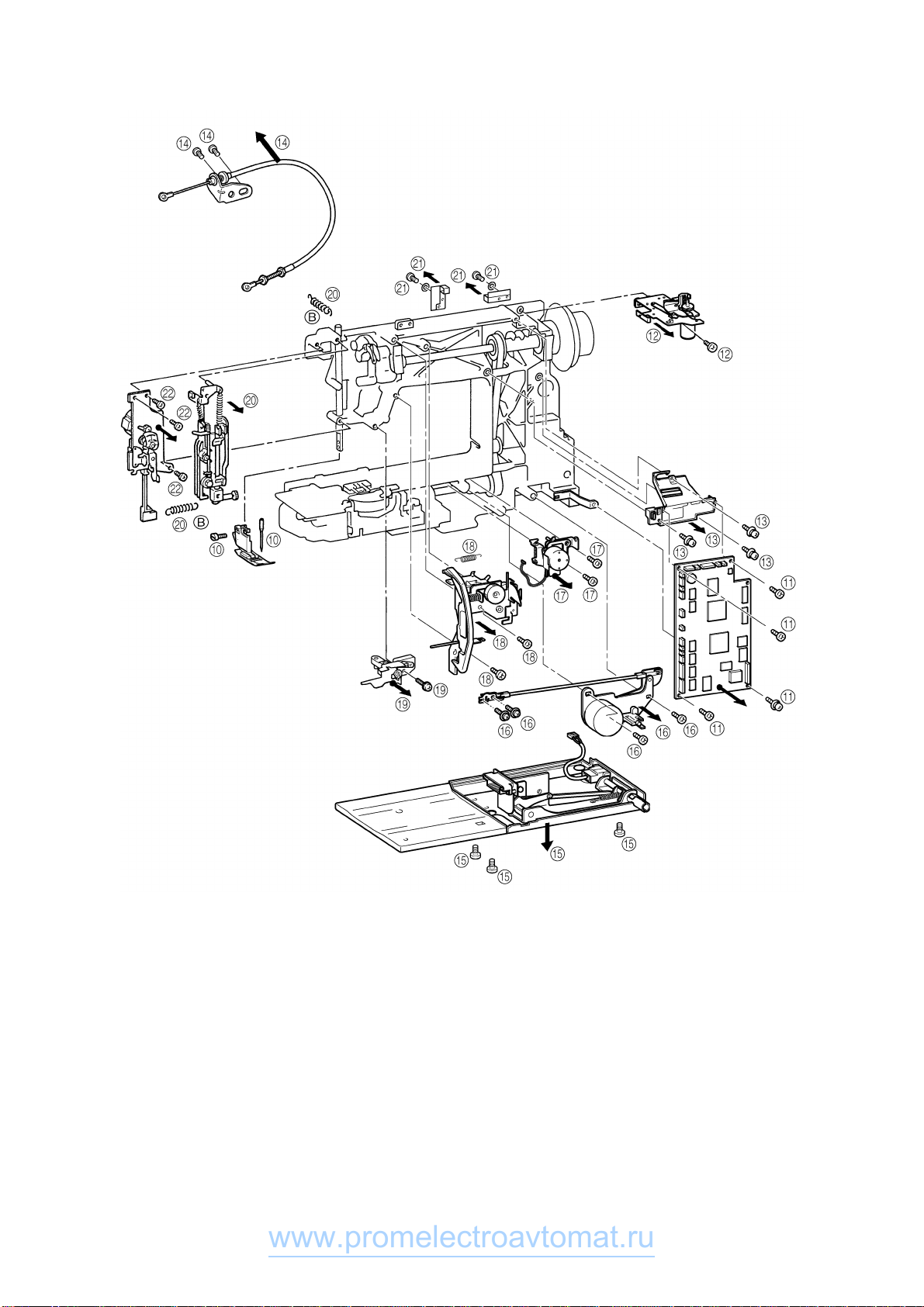
10. Remove the presser holder and needle.
11. Remove the 17 connectors, the four screws, and the main PC board.
12. Remove the screw and thread winding assembly.
13. Remove the three screws and NP base assembly.
14. Remove the two washers. Remove the 2 screws and the wire support plates. Remove the wire assembly .
15. Remove the inlet assembly connector. Then the 3 screws and base plate assembly.
16. Remove the two screws on the left. Remove the two screws and the side feed assembly.
17. Remove the two screws and the FPM holder.
18. Remove the spring, and remove the two screws. Remove the thread tension assembly.
19. Remove the screw and the needle bar supporter stud holder assembly.
20. Remove the two springs (B) and the needle bar block assembly.
21. Remove the two screws and the two cord holders.
22. Remove the three screws and the ZPM assembly.
Disassembly Points
11. To disconnect the connectors, grab the base of the connector and pull it straight out.
∗In order to reduce the risk of static electric damage to the main PC board after it is removed from the
sewing machine, do not touch the board’s front surface and only carry it by its edges in the same way
that you hold a compact disk.
19. To remove the needle bar supporter stud holder, move it upward while removing it from the pin.
www.promelectroavtomat.ru
-11-
www.promelectroavtomat.ru
-12-
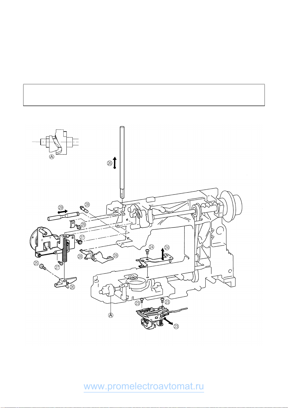
23. Remove the connector, then remove the two screws and the thread cutter unit.
24. Remove the screw and the inner rotary hook rotation prevention bracket.
25. Remove the presser bar clamp screw.
26. Remove the presser bar by lifting it from above, and the presser bar clamp and presser spring.
27. Remove the two screws, and remove the presser frame assembly.
28. Remove the presser lifting shaft by pulling it out from the back, the presser lifter and lifter.
29. Remove the screw and the thread take-up shaft.
Disassembly Point
23. Before removing the thread cutting assembly, move the thread cutter cam so that its notch faces the front
of the sewing machine (A).
www.promelectroavtomat.ru
-13-
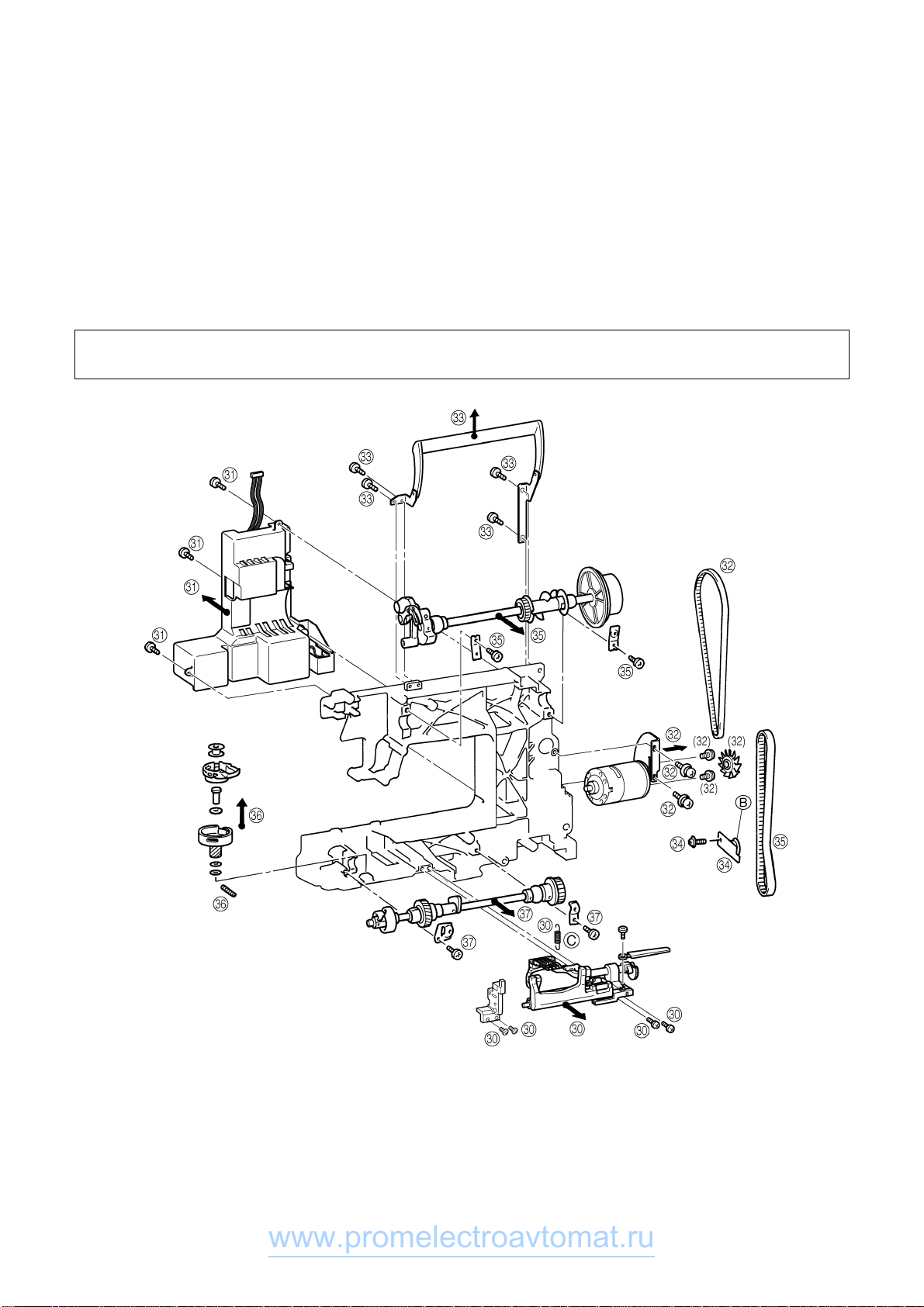
30. Remove the 4 screws from the horizontal feed shaft supporter and the feed adjustment unit shaft supporter.
Remove the horizontal feed assembly.
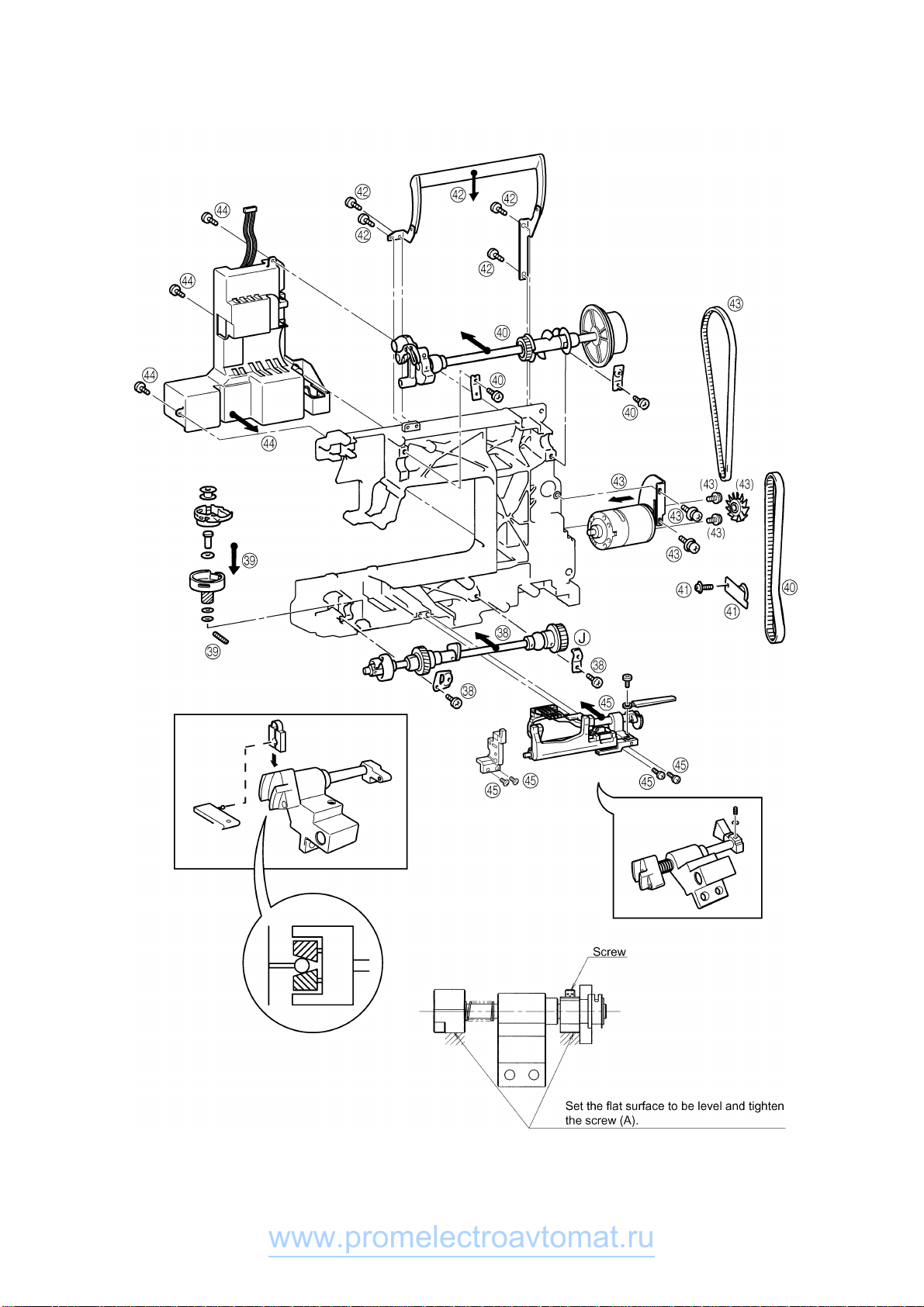
31. Pull out the motor connector. Remove the 3 screws and the power supply unit.
32. Remove the motor belt and the 2 screws and the main motor.
(When removing the motor from the motor holder, remove the motor fan then remove the 2 screws.)
33. Remove the four screws and the handle.
34. Remove the screw and the tension pulley holder.
35. Remove the two screws securing the upper shaft metal, the upper shaft assembly and the timing belt.
36. Remove screw and the outer rotary hook assembly .
37. Remove the both presser plate screws. Remove the lower shaft assembly and the timing belt.
Disassembly Points
30. Before removing the horizontal feed assembly, remove the feed bar tension spring (C).
www.promelectroavtomat.ru

-14-
38. Use the presser plate and the screw to attach the lower shaft assembly.
39. Position the outer rotary hook assembly and the three washers to the lower shaft assembly (see diagram
below) and attach with the screw.
40. Run the upper shaft through the timing belt and attach with the two presser plates and the screws.
41. Attach the tension pulley holder with the screw.
42. Attach the handle with four screws.
43. Attach the main motor using the two screws and catch the motor belt.
(When attaching the motor to the motor holder, tighten the two screws and then attach the motor fan.)
44. Attach the power supply unit assembly using the three screws connect the motor connector.
45. Use the 2 screws to attach the horizontal feed shaft supporter. Use the two screws to attach the horizontal
feed assembly. Attach the feed stand spring.
Assembly Points
38. When attaching the lower shaft assembly, do so with the notch of the lower shaft eccentric metal (A)
facing forwards and slot (B) in the lowermost position.
38. After lower shaft is attached, make sure that the lower shaft moves freely. If it does not move freely,
lightly tap the lower shaft metal presser (J) with a punch, or similar tool, and check again.
39. When attaching the outer rotary hook assembly, attach so that the lower shaft base hole (C) of the thread
cutter cam and the outer rotary hook assembly baseline (D) are positioned towards the front.
39. ∗Of the three rotary shaft washers, install the thin washer with the large inner diameter (dia. 6mm,
thickness 0.2mm) on top of the rotary hook, the think washer (thickness 3mm) below the rotary hook and
then the thin washer with the small inner diameter (dia. 5mm, thickness 0.2mm) below that.
39. ∗Adjust position of notch of eccentric metal to adjust play of the outer rotary hook assembly and the lower
shaft (rotation direction slack of the outer rotary hook assembly). Positioning the notch at the bottom will
reduce play. Under normal conditions, the ideal position is towards the front. However, when play is
excessive, adjust to prevent the rotary hook noise.
41. After tension pulley is attached, adjust tension of the timing belt. (see (H) for reference.)
∗After attaching the timing belt, adjust rotation torque of the timing belt.
41. When attaching the timing belt, do so when notch (G) of the horizontal feed cam of the timing belt and the
lower shaft baselines (C) and (F) are facing positioned on the front side.
43. Apply a pressure of 1N (100 g) at the center of the motor belt, then adjust its tension until it only moves
1.5 to 3.5 mm (B).
∗If the belt is too tight, the torque becomes too much, causing the motor to rotate slower and generate an
irregular noise. If the tension is too loose, the belt may jump and the upper shaft may not rotate smoothly
while sewing on denim and other thicker fabrics or overlapping fabrics.
45. Check back and forth movement of feed stand.
∗If free movement is hindered, feed pitch is inhibited or a forward and backward motion is inhibited.
www.promelectroavtomat.ru
-15-
www.promelectroavtomat.ru

-16-
46. Attach the thread take-up shaft using the screw and presser plate.
47. Attach the lifter and the presser foot lifter with the presser foot shaft.
48. Attach the presser frame assembly using the two screws.
49. Insert and attach the presser bar with spring into the presser bar clamp.
50. Attach the presser bar clamp screw.
51. Attach the inner rotary hook rotation prevention plate using the screw.
52. Attach the thread cutter unit using the two screws connect the thread cutter solenoid connector.
Assembly Points
46. The thread take-up lever shaft should be installed so that there is no gap between the right side of the
thread take-up and the stop ring. If there is a large gap, the right and left clearance may generate an
irregular noise (thread take-up lever noise).
51. Install the inner rotary hook bracket assembly. (Firmly tighten the screw to make no space between (D)
and the arm so that the inner rotary hook bracket assembly does not rotate.)
∗After the inner rotary hook bracket assembly is installed, adjust the position where rotation is prevented.
(Refer to (A).)
∗If there is a small rotation prevention amount, the inner rotary hook may slip and start rotating causing
damage to the inner rotary hook or breaking the needle.
52. Before installing the thread cutting assembly, move the thread cutter cam so that its notch faces the front
(B) of the sewing machine.
52. Check (E) and adjust (F) so that the height of the lower thread guide is such that the highest point is at
almost the same height as the inner rotary hook rib. If the height is not correct, defective thread cutting
and thread tension will occur.
52. Thread cutting assembly installation procedure
(1) Insert the projection (C) on the cutter unit into the arm guide hole.
(Insert the projection while checking that the inner rotary hook is correctly positioned.)
(2) Move the thread cutting assembly toward the right without bending the lower thread guide arm assembly
to install it.
∗After installing the thread cutting assembly, perform the following procedure to check that the movable
blade operates correctly.
(1) With the lever pin pressed in by hand, turn the balance wheel by hand to begin operating the movable
blade.
(2) When the movable blade is at its rightmost position, release the lever pin and turn the balance wheel, then
check that the movable blade lightly returns to its previous position.
∗If the movable blade does not operate correctly, loosen the screw (52), move the thread cutting
assembly forward and backward, then move the unit toward the right and tighten the screw.
www.promelectroavtomat.ru

-17-
www.promelectroavtomat.ru

-18-
53. Attach the ZPM holder assembly using the three screws.
54. Wrap the lead wire cord, then tighten the 2 screws on the 2 cord holders.
55. Attach the needle bar supporter assembly using the two springs. (Insert into the needle bar clamp and
needle bar crank rod)
56. Attach the needle bar supporter stud holder using the screw. (Insert the needle bar supporter arm into the
pin on the needle bar supporter.)
57. Insert the pin, and attach the thread tension assembly using the two screws and the spring.
58. Attach the FPM holder assembly using the two screws.
59. Attach the side feed shaft using the 2 screws on the left and attach the side feed assembly with 2 screws.
60. Attach inlet assembly connector. Attach the base plate assembly using the three screws.
61. Attach wire assembly using the four screws. Use the two washers to hook up to lift wiring.
62. Attach the NP base assembly using the three screws. Pass the wires from the back side through hook
section (E) of the NP base assembly.
63. Attach the thread winder assembly using the screws.
64. Attach the main board assembly using the four screws. Connect the 17 connectors.
65. Attach the presser holder and needle.
Assembly Points
53. When installing the ZPM holder assembly, the cloth selecting sensor lever should be put on the presser
bar clamp.
∗If the cloth selecting sensor lever slips down, the cloth selecting sensor cannot operate and the thread
tension cannot be adjusted.
55. Before installing the needle bar supporter assembly, insert it into the needle bar crank rod, insert the
needle bar supporter stud holder, then install a spring. Hook the longer end of the other spring (F) to the
main unit.
56. Install the needle bar supporter stud holder from the needle bar supporter pin side, then attaching it using
a 14 mm screw.
57. <Initial adjusting system - Tension unit assembly (XA9551-101) parts assembly method>
(1) Insert one end of the spring (b) into the small hole (dia. 1mm) of the thread tension cam.
(2) Insert the other end of the spring (b) into the small hole of the thread tension gear cover (c), put the 3
parts (a), (b) and (c) together, insert the thread tension plate assembly (d) dia. 4mm shaft through the
thread tension cam (a) rotation center hole, set the thread tension plate (e) dia. 3mm shaft in the thread
tension cam (a) cam groove and then fit the stop ring (f).
(3) Rotate the thread tension gear cover (c) clockwise with respect to the thread tension cam (a), and insert
the dia. 2mm shafts in the dia. 2mm holes when they are aligned.
(4) Install the ATPM (g) with the two screws (n) and remove the dia. 2mm shaft.
(5) Attach the rubber (i) to the curved part of the initial adjust plate (j).
(6) Temporarily attach the initial adjust plate (j) to the thread tension plate assembly with the screw (k).
(At this time, ensure that the initial adjust plate can be slid 2 to 3 mm left and right by hand.)
Refer to "12. Adjusting the upper thread tension" on page 42.
Old/new comparison table Old Adjusting system
Tension unit assembly XA9551-001 XA9551-101
Thread tension plate assembly Not supplied (XA9553-051)*1 XA9553-251
Thread tension cam XA9565-000 XC3252-001*2
Rubber None XC3253-051
Initial adjust plate None XC3254-051
*1 When replacing, order XA9551-101. *2 "AD" is engraved.
58. When installing the FPM holder assembly, align the guide points of the F gear and the FPM gear.
www.promelectroavtomat.ru
This manual suits for next models
5
Table of contents
Other promelectroavtomat Sewing Machine manuals


