promelectroavtomat XL2120 User manual

SERVICE MANUAL FOR
XL2120
XL2121
XL2130
XL2140
XL2220
XL2230
XL2240
XL2250
7.2003.
www.promelectroavtomat.ru

CONTENTS
Disassembly Procedure
Disassembly Procedure .....................................................................................2 - 1
Needle Bar-Presser Unit Assembly ...................................................................2 - 5
Lower Shaft Unit Assembly ................................................................................2 - 7
Thread Tension Assembly .................................................................................2 - 8
Assembly Procedure
Assembly Procedure ..........................................................................................2 - 9
Front Cover ........................................................................................................2 - 9
Rear Cover ......................................................................................................2 - 10
Thread Tension Assembly ...............................................................................2 - 14
Needle Bar-Presser Unit Assembly .................................................................2 - 15
Lower Shaft Unit Assembly ..............................................................................2 - 17
Adjustment
Adjustment of the Timing Belt Tension ..............................................................3 - 1
Adjustment of the Motor Belt Tension ................................................................3 - 2
Adjustment of the Needle Bar Stopper ..............................................................3 - 3
Adjustment of the Needle Sidewise Movement (Needle Swing Timing) ............3 - 4
Adjustment of the Left/Right Position of Zigzag Needle Down ..........................3 - 5
Left and Right Balance of the Needle Clearance ...............................................3 - 6
Adjustment of the BH Left Over Edging (Zero Feed Adjustment) ......................3 - 7
Adjustment of the zigzag width for BH Right Over Edging ................................3 - 8
Adjustment of the Feeding for BH Right Over Edging
(Adjustment of Satin Feeding) ...........................................................................3 - 9
Forward/Reverse Adjustment of the Super Stitch Feeding ..............................3 - 10
Adjustment of Forward/Back Position of Needle Against the Needle Hole
in the Presser Foot ..........................................................................................3 - 11
Adjustment of the Amount of Needle Bar Rise ................................................3 - 12
Adjustment of the Needle Bar Height ..............................................................3 - 13
Adjustment of the Needle Clearance ...............................................................3 - 14
Adjustment of the Presser Bar Height .............................................................3 - 15
Adjustment of the Feed Dog Height .................................................................3 - 16
Forward/Back and Left/Right Position Adjustment of the Feed Dog ................3 - 17
Adjustment of the Position of the Inner Rotary Hook Rotation Prevention
Bracket .............................................................................................................3 - 18
Adjustment of the Upper Thread Tension ........................................................3 - 19
Adjustment of the Inner Rotary Hook (Lower Thread) Tension .......................3 - 20
Adjustment of the Thread Winding
(Uneven Bobbin Winding and Amount of Thread Winding) .............................3 - 21
www.promelectroavtomat.ru

2 - 1
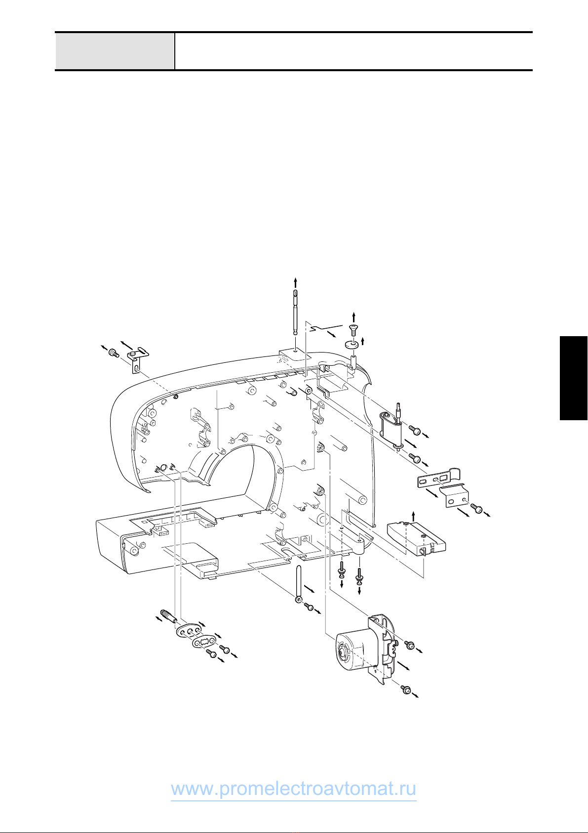
Disassembly Procedure
1. Remove the needle plate B and take out the inner rotary hook.
2. Remove the one screw securing the face plate and then remove the face plate to the front.
3. Pull out the selection dial on the front face of the front cover.
4. Remove the screws fastening the front cover, one in the front (giza tite 5 ×16) and six in the back (five giza
tite M 5 ×16, and one giza tite M 3 ×32), to remove the front cover.
5. Remove the two screws (taptite, bind B M 4 ×12) to remove the thread tension dial assembly.
6. Remove the one screw (taptite, bind B M 4 ×12) to remove the thread conductor B assembly.
7. Pull out the reverse stitching knob.
4
2
2
3
1
4
4
44
4
4
7
4
5
5
5
6
6
Disassembly Procedure
www.promelectroavtomat.ru

2 - 2
Disassembly Procedure
Disassembly
Procedure
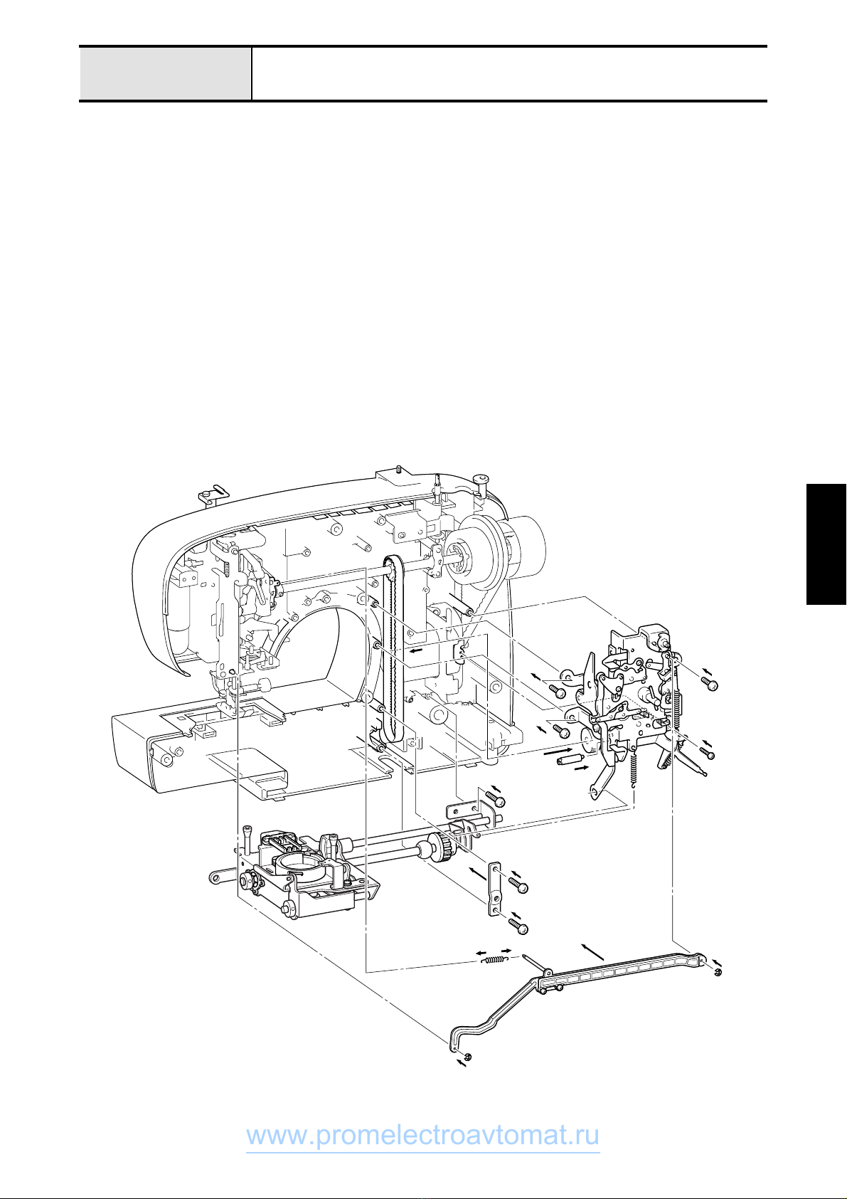
8. Remove the pull spring of the Z linkage. (Ø6 ×22 mm)
9. Remove the retaining ring E3 that links the Z linkage and the selection unit and E5 that links the Z linkage
and the needle bar supporter and then remove the Z linkage.
10. Remove the feed transmission spring that fastens the selection unit. (Ø5 ×21 mm)
11. Remove the four screws (three giza tite 5 ×16, and one step screw) that fasten the selection unit and remove
the selection unit.
12. Remove the two screws (giza tite 5 ×16) securing the lower shaft metal retainer to remove it.
13. Remove the one screw (giza tite 5 ×16) for the feed transmission holder.
14. Remove the two screws (giza tite 5 ×16) holding the base plate assembly and remove the feed module.
15. Remove the screw holding the lamp and remove the lamp unit. (3 ×20)
B
DD
D
C
A
A
A
A
B
B
8
9
9
9
A
E
E
www.promelectroavtomat.ru

2 - 3
Disassembly Procedure
16. Remove the screw for needle clearance adjustment. (2.5 ×25 mm)
17. Remove the four screws (giza tite 5 ×16) securing the upper shaft metal retainer to remove it.
18. Remove the two screws (giza tite 5 ×16) securing the needle bar-presser unit assembly and then remove the
upper shaft assembly and the needle bar-presser unit assembly.
19. Remove the tension belt and the motor belt from the needle bar-presser unit assembly.
20. Loosen the screw (set screw, socket (FT) M 5 ×5) for the thread take-up lever crank and separate the upper
shaft assembly from the needle bar-presser unit assembly.
I
I
J
J
H
G
G
G
G
G
G
H
H
F
www.promelectroavtomat.ru
2 - 4
Disassembly Procedure
Disassembly
Procedure
21. Remove the one screw (giza tite 5 ×16) and remove the cord retainer and the thread winding retainer.
22. Remove the two screws (giza tite 5 ×16) to remove the bobbin assembly.
23. Remove the one screw (taptite, bind B M 4 ×10) to remove the shield wire clip.
24. Remove the two screws (giza tite 5 ×16) to remove the motor.
25. Remove the two screws (screws, pan (S/P washer) M 3 ×20) to remove the three pole lamp socket.
26. Remove the two screws (taptite, bind B M 4 ×10) to remove the Plate apring, the adjusting plate, and the
adjusting screw.
27. Remove the spool pin spring and remove the spool pin.
28. Remove the one screw (giza tite 5 ×16) to remove the lower thread guide assembly.
29. Remove the two screws (giza tite 4 ×14) to remove the bobbin retainer.
R
PP
P
P
P
OO
O
N
N
M
M
R
Q
S
S
Q
L
L
K
K
K
L
N
www.promelectroavtomat.ru

2 - 5
Disassembly Procedure
Needle Bar-Presser Unit Assembly
1. Remove the needle bar crank rod.
2. Remove the screw (screws pan (S/P washer) M 3 ×8DB) of the stud for thread take-up lever supporter by
pulling it out to the right, and them remove the thread take-up lever supporter and the dome spring washer.
3. Remove the thread take-up lever body and the needle bar crank from the thread take-up lever supporter.
4. Remove the screw and the spring at the top of the needle bar supporter and remove the needle bar supporter
from the base holder assembly.
4
4
4
4
1
3
2
2
2
2
2
www.promelectroavtomat.ru

2 - 6
Disassembly Procedure
Disassembly
Procedure
5. Loosen the one screw (set screw, socket (FT) M 4 ×4) securing the needle bar clamp to remove the needle
bar assembly.
6. Remove the one screw (size 2.38) of the needle bar and remove the needle clamp, the needle bar thread
guard, and the needle set screw.
7. Remove the one screw (screws pan (S/P washer) M 3 ×8DA) at the bottom of the needle bar supporter and
remove the Z fine adjusting plate from the needle bar supporter.
8. Remove the screw (3.57L) to remove the thread take-up lever supporter and the stud for thread take-up lever
supporter.
9. Loosen the screw (set screw, socket, (CP) M 5 ×8) securing the presser bar clamp to remove the presser bar.
10. Remove the one screw (bolt, socket M 3 ×6) for the stopper to remove the stopper.
11. Remove the one screw (bolt, socket M 3 ×6) for the needle bar supporter stud holder to remove the needle
bar supporter stud holder assembly.
12. Remove the retaining ring E5 and remove the presser lifter.
13. Remove the retaining ring E3 and remove the thread loosening lever.
14. Remove the one screw (screw, bind M 4 ×6) for the lamp holder to remove the lamp holder.
6
6
6
6
5
6
7
5
7
0
0
B
9
B
C
C
C
99
9
9
A
A
88
www.promelectroavtomat.ru

2 - 7
Disassembly Procedure
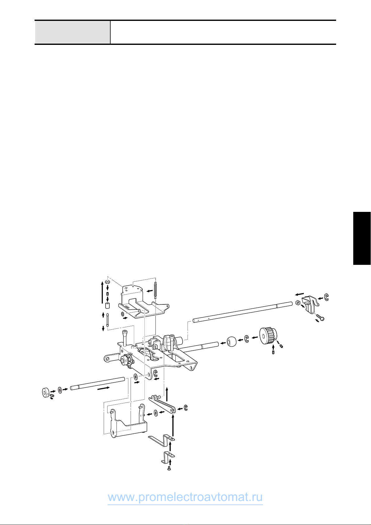
Lower Shaft Unit Assembly
1. Remove the retainer ring E4 and loosen the screw (screw, bind M 4 ×14) to remove the feed transmission lever.
3. Remove the two screws (M4) to remove the needle plate A.
4. Remove the one screw (screws pan (S/P washer) M 3 ×6) and remove the inner rotary hook rotation
prevention bracket assembly.
5. Remove the two screws (screw, bind M 3 ×6) to remove the feed dog.
6. Loosen the screw (set screw, socket (CP) M 4 ×4) for the rotary hook shaft receptacle and remove the rotary
hook assembly.
7. Remove the three retainer rings E3 from the vertical feed shaft and then remove the vertical feed shaft and
the feed adjuster.
8. Loosen the two screws (set screw, socket (CP) M 4 ×4) on the lower shaft set collar and then remove the set collar.
9. Remove the one screw (screw, bind M 3 ×4) and remove the feed auxiliary plate.
10. Remove the three screws (screw, bind M 3 ×6) to remove the metal retainer B.
11. Remove the metal.
12. Remove the retainer ring E6 from the timing pulley side of the lower shaft, loosen the screw (set screw,
socket (CP) M 4 ×4), and then remove the timing pulley.
13. Remove the lower shaft assembly.
14. Remove the retainer ring E5 from the horizontal feed shaft and then remove the horizontal feed shaft.
15. Remove the feed base tension spring (Ø3 ×10.5 mm).
16. Remove the two screws (screw, bind M 4 ×20) to remove the rotary hook shaft receptacle.
17. Remove the retainer ring shaft CS and then remove the feed arms A and B from the feed base assembly.
18. Remove the retainer ring shaft CS and the feed arm B.
19. Remove the feed arm receptacle.
20. Remove the feed adjuster shaft assembly.
6
F
FF
6
1
1
5
5
33
3
5
F
F
8
8
9
9
9
0
0
00
A
E
4
4
GG
7
7
7
7
7
7
A
8
D
D
D
D
B
B
C
B
B
J
I
www.promelectroavtomat.ru

2 - 8
Disassembly Procedure
Disassembly
Procedure
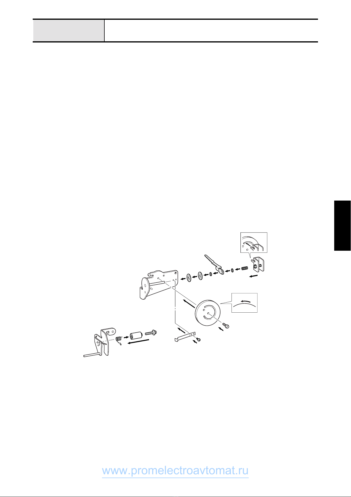
Thread Tension Assembly
1. Remove the holding screw (screw, pan M 3 ×4) to remove the notch spring.
2. Set the thread tension dial to 9 and remove the thread tension dial shaft.
3. Remove the thread loosening plate.
4. Remove the thread tension adjusting screw from the thread loosening plate.
5. Remove the following items in the following order: the spring, the washer, the tension spring receptacle, the
thread tension stud, the washer, the thread tension disc B, and the thread tension disc A.
6. Remove the one screw (screws pan (S/P washer) M 3 ×18DA) and remove the thread take-up spring case
and the thread take-up spring.
9
8
2
5
5
5
5
5
5
3
4
2
1
6
1
2
www.promelectroavtomat.ru

2 - 9
Assembly Procedure
Assemble and install the units first before attaching the front cover and the rear cover
Front Cover
1. Insert the thread tension dial into the square hole of the front cover, set the thread conductor, and secure with
the two screws (taptite, bind B M 4 ×12).
2. Insert the tip of the wire of the thread conductor B assembly by aligning it against the positioning groove of
the front cover and secure with the screw (taptite, bind B M 4 ×12) that sets the protrusion of the thread
conductor B into the hole in the front cover.
1
1
2
2
1
Assembly Procedure
www.promelectroavtomat.ru

2 - 10
Assembly Procedure
Assembly
Procedure
Rear Cover
1. Temporarily fasten the lower thread guide assembly with the one screw (giza tite 5 ×16).
2. Insert the spool pin into the rear cover and then attach the spool pin spring onto it.
3. Attach the adjusting plate, Plate apring, and the adjusting screw in this order and secure them with the two
screws (taptite, bind B M 4 ×10).
4. Place the foot of the motor holder underneath the motor and secure it with the two screws (one giza tite 3 ×
10, and two giza tite 5 ×16).
5.
Fasten the three pole socket assembly with the screw (pan head screw with spring and plain washers, size 3
×
20).
6. Route and connect the lamp unit harness.
7. Secure the bobbin assembly with the two screws (giza tite 5 ×16).
8. Fasten the cord retainer and the thread winding spring with the one screw (giza tite 5 ×16).
1
6
6
3
33
3
3
3
4
4
55
5
4
4
4
1
2
2
7
7
8
8
8
7
4
4
www.promelectroavtomat.ru

2 - 11
Assembly Procedure
9. Loosen the screw (set screw, socket (FT) M size 5 ×5) for the thread take-up lever crank at the screw
alignment position to connect the upper shaft assembly from the needle bar-presser unit assembly.
10. Attach the tension belt and the motor belt to the upper shaft assembly and the needle bar-presser unit
assembly.
11. Attach the upper shaft assembly and the needle bar-presser unit assembly to the front cover and secure with
the two screws (giza tite 5 ×16) on the side of the needle bar-presser. Then place the upper shaft metal
retainer on the upper shaft metal and fasten it with the screw (giza tite 5 ×16).
00
9
9
A
A
A
A
A
A
A
www.promelectroavtomat.ru
2 - 12
Assembly Procedure
Assembly
Procedure
12. Temporarily fasten the screw for needle clearance adjustment. (2.5 ×25 mm)
13. Secure the lamp unit to the base holder assembly with the screw (3 ×20).
14. Fit the feed module in the rear cover and secure it with the two screws (giza tite 5 ×16) of the base plate
assembly. Then place the lower shaft metal retainer on the lower shaft metal and fasten it with the screw
(giza tite 5 ×16).
15. Put the worm pulley of the selection unit through the timing belt and set it in the mounting position on the
rear cover.
16. Secure the selection unit with the four screws (three giza tite 5 ×16, and one giza tite 5 ×16).
17. Install the worm pulley of the selection unit.
18. Attach the ends of the pull spring of the feed transmission lever to the middle shaft of the Z linkage and the
upper shaft metal. (Ø5 ×21 mm)
19. Attach the Z linkage to the shafts located at upper right of the selection unit and below the needle bar
supporter.
20. Attach the retaining ring E5 that links the Z linkage and the needle bar supporter.
21. Attach the retaining ring E3 that links the Z linkage and the selection unit.
22. Attach the pull spring of the Z linkage. (Ø6 ×22 mm)
D
C
G
F
FF
F
D
D
HI
J
E
E
K
www.promelectroavtomat.ru

2 - 13
Assembly Procedure
23. Install the reverse stitching knob.
24. Tighten the screws for fastening the front cover, one in the front (giza tite 5 ×16) and six in the back (five
giza tite 5 ×16, and one giza tite 3 ×32), to secure the front cover.
25. Attach the selection dial on the front face of the front cover.
26. Fasten the face plate with the one screw for holding it.
27. Install the inner rotary hook and attach the needle plate B.
N
P
P
O
Q
N
N
N
N
N
N
M
P
www.promelectroavtomat.ru
2 - 14
Assembly Procedure
Assembly
Procedure
Thread Tension Assembly
1. Mount the following items in the following order: @@ (the thread tension stud?), the thread tension disc A,
the thread tension disc B, the washer, the tension spring receptacle, the washer, and the spring.
2. Mount the thread tension adjusting screw on the thread tension stud aligning it to the thread tension cam
groove in the thread tension dial.
3. Set the thread tension dial to 9 and attach the thread tension dial shaft.
4. Align the notch spring against the oval hole and secure it with the screw (screw, pan M 3 ×4).
5. Attach the thread take-up spring in the second hole from the bottom of the thread take-up spring case so that
the thread guard side fits between two protrusions of the spring case.
6. Insert the positioning protrusion of the thread take-up spring case assembly into the square hole of the thread
conductor B, shift it all the way up in the square hole, and secure it with the one screw (screw, pan (S/P
washer) M 3 ×18DA).
9
8
3
1111112
2
2
4
5
6
4
3
www.promelectroavtomat.ru
2 - 15
Assembly Procedure
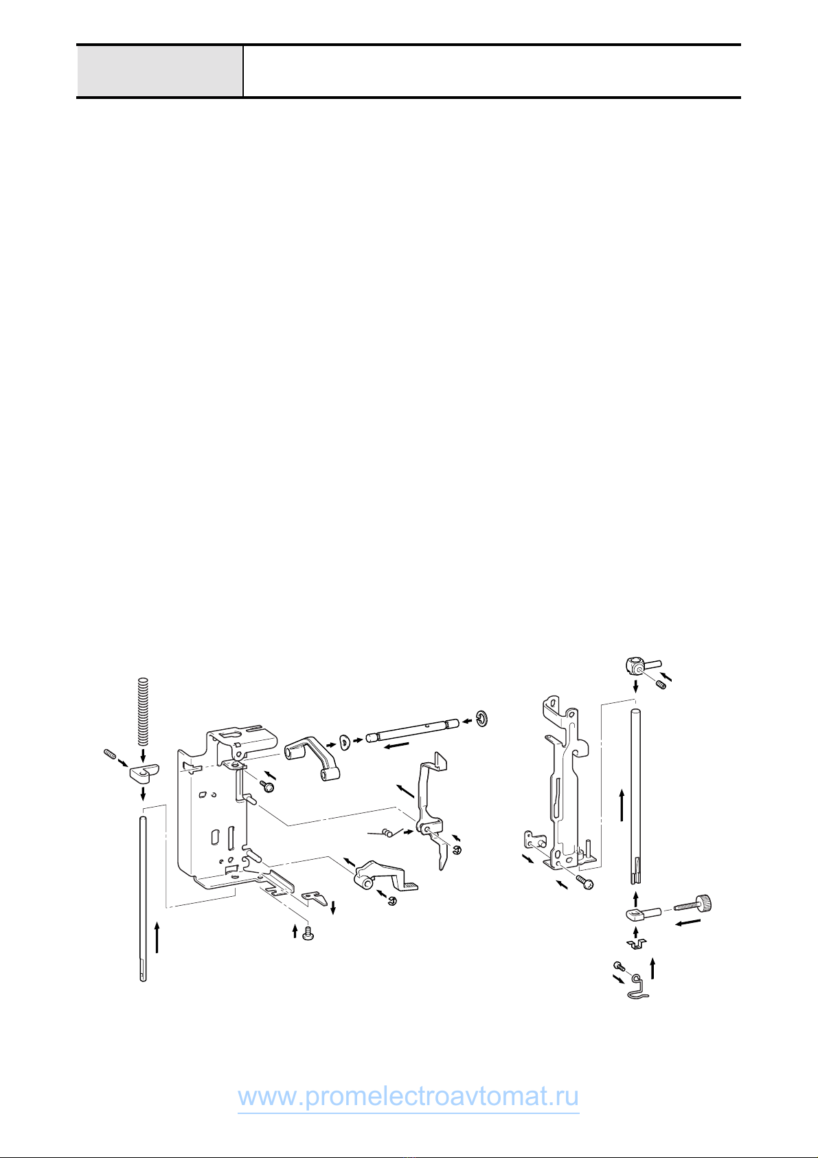
Needle Bar-Presser Unit Assembly
1. After setting the lever spring in the letter V direction in the U-bend part of the thread loosening lever and
inserting into the base holder shaft, attaché the retaining ring CS4. (The lever spring should be rested on the
base holder on the left side and on the upper side of the U-bend part on the right side.)
2. Insert the presser lifter in the presser lifter shaft and attach the retainer ring E4.
3. Align the protrusion of the needle bar stopper against the U groove of the base holder and temporarily fasten
it with the one screw (bolt, socket, M 3 ×6) from the back.
4. Set the screw (set screw, socket (CP) M 5 ×8) on the presser bar clamp, insert the presser bar into the base
holder, the presser bar clamp, and the spring in this sequence, and temporarily fasten the screw (set screw,
socket (CP) M 5 ×8).
5. Align the reference hole for fixing against the protrusion of the base holder and secure it with the one screw
(screw, bind B M 4 ×6) from the back.
6. Attach the retaining ring E5 to the stud for thread take-up lever supporter.
7. Insert the dome spring washer into the stud for thread take-up lever supporter with its convex side facing the
retaining ring.
8. Insert the thread take-up lever supporter into the stud for thread take-up lever supporter.
9. Insert the stud for thread take-up lever supporter into the base holder and secure it with the one screw
(Phillips, pan head screw with spring and plain washers, size 3 ×8DB).
10. Insert the riveting stud for the Z fine adjusting plate from behind the needle bar supporter and temporarily
fasten it with the screw (Phillips, pan head screw with spring and plain washers, size 3 ×8DB).
11. Insert the plate to prevent reverse attachment of needle from behind the needle bar clamp (the cut surface)
until it reaches above the needle clamp.
12. Insert the needle clamp into the needle bar, bring it up as far as it goes, and temporarily fasten it with the
needle set screw.
13. Secure the needle bar thread guard with the 2.38 screw.
14. Temporarily insert the needle bar into the needle bar supporter, run it through the needle bar clamp of the
needle bar crank rod assembly, and temporarily fasten with the screw (set screw, socket (FT) M 4 ×4).
C
B
A
9
D
6
87
B
C
0
D
D
0
3
3
2
9
2
1
1
1
4
4
4
4
www.promelectroavtomat.ru

2 - 16
Assembly Procedure
Assembly
Procedure
15. Set the needle bar supporter in the base holder, insert the push spring into the gap between the needle bar
supporter and the base holder, and force the needle bar supporter stud in.
16. Attach the lock nut to the needle bar supporter stud, turn it until it levels with the base holder, and then
tighten it.
17. Temporarily insert the needle bar supporter arm into the pin of the needle bar supporter.
18. Insert the needle bar supporter arm into the riveting pin for the needle bar supporter stud holder and attach
the retaining ring E2.
19. Insert into the U groove of the base holder of the needle bar supporter stud holder and temporarily fasten
with the one screw (bolt, socket M 3 ×6) approximately in the center of the oval hole of the needle bar
supporter stud holder.
20. Assemble with the thread take-up lever body and the needle bar crank and fasten with the Phillips, flat
countersunk head screw, size 3.57.
21. Insert the riveting stud of the thread take-up lever body for the thread take-up lever supporter into the thread
take-up lever supporter.
22. Insert the needle bar crank rod in to the needle bar crank and the needle bar clamp shaft.
E
F
E
G
H
H
I
I
K
L
L
JJ
www.promelectroavtomat.ru

2 - 17
Assembly Procedure
Lower Shaft Unit Assembly
1. Insert the push spring in the feed adjuster assembly which is then inserted into the shaft receptacle of the base
plate from the left.
2. Insert the feed arm receptacle to the end face of the base plate.
3. Snap on the retainer ring E6 in the retainer spring groove on the left of the lower shaft and attach the thrust
washer on the shaft from the left.
4. Insert the lower shaft assembly into the base plate.
5. Attach the lower shaft metal on the left of the lower shaft, set the metal retainer B, and secure with the three
screws (screws, bind M 3 ×6).
6. After attaching the thrust washer and the set collar on the left of the lower shaft, slide the set collar toward
the metal, and tighten the screw (set screw, socket (CP) M 4 ×4).
7. Insert the vertical feed shaft into the base plate, slide the vertical finger and the washer on the shaft, and
attaché the retainer rings E3 on the inner left of the base plate as well as outside of the vertical finger (on both
the left and the right).
1
4
3
3
5
5
5
5
6
6
66
5
1
7
7
7
7
7
72
www.promelectroavtomat.ru
2 - 18
Assembly Procedure
Assembly
Procedure
8. Attach the polyslider first and then the feed arm B on the riveting stud of the feed arm A, and apply the
retainer ring shaft CS.
9. Insert the feed arms A and B assembly into the base plate from below, and place the feed regulator slide shaft
inside the feed adjuster.
10. After inserting the polyslider between the feed arm A and the base plate, insert the horizontal feed shaft from the left.
11. Snap on the retainer ring E5 to the horizontal feed shaft from inside of the base plate.
12. Slide the polyslider and the set collar on the horizontal feed shaft from the left, place them on the left hand
side, and tighten the two screws (set screws, socket, CP, size 4 ×4).
13. Tighten the screw (set screw, socket (CP) M 4 ×10) on the vertical adjuster.
14. Assemble the screw (set screw, socket (CP) M 4 ×10) with the lock nut, drive it into the feed base, and then
tighten the lock nut.
15. Slide the feed base on riveting stud of the feed arm A and snap on the retainer ring shaft CS to the shaft on
the left hand side.
16. Attach the vertical rod between the vertical adjuster and the vertical finger.
17. Attach the feed tension spring on the feed base and the base plate.
18. Align the protrusion of the feed auxiliary plate B against the groove in the feed auxiliary plate and fasten
with the screw (screws, bind M 3 ×4).
19. Attach the lower shaft metal to the right hand side of the lower shaft and snap on the retainer ring E6 in the
retainer ring groove on the inner side of the lower shaft.
20. Turn the lower shaft so that the spring pin of the lower shaft gear is at its lowest position and the horizontal
feed cam faces to the front. Slide the timing pulley D on the shaft with the pulley's screw head facing to the
right, position the pulley so that its screw (set screw, socket (CP) M 5 ×5) faces to the front and the other
screw to the top, and then temporarily tighten the screws.
21. Set the Class 2 nut 4 on the bottom side of the feed transmission lever and temporarily fasten with the screw
(screws, bind 4 ×14).
22. Attach the feed transmission lever to the feed adjuster shaft, snap on the retaining ring E4 in the retainer ring
groove on the right, slide the feed transmission lever toward the retainer ring, and temporarily fasten it.
C
D
F
9
H
H
H
8
8
II
J
J
K
L
L
K
J
A
8
00
B
B
B
C
E
G
www.promelectroavtomat.ru
This manual suits for next models
7
Table of contents
Other promelectroavtomat Sewing Machine manuals


