promelectroavtomat QD55 Series User manual

Quick-Rotan Elektromotoren GmbH
Gräfenhäuser Straße 85
D-64293 Darmstadt
Tel.: 0 61 51/87 97-0
Fax: 0 61 51/896 246
English 11.12.96
Type
Instruction Manual
Part 2
Valid as from revised software 4A_001_6.HEX
PFAFF
ElectronicStop
P20K2
Series: digital K2
QD55x / QE55x
www.promelectroavtomat.ru

The symbol confirms that the respective drive system meets the
requirements for partial machines of the following EU directives:
- EMV Directive 89/336/EWG
- Low Voltage Directive 73/23/EWG
P20K2TI-2E 111296
www.promelectroavtomat.ru

Contents
7. Description of the drive system 7.1 - 7.6
7.1 Basic motor (QD55x, QE55x)
7.1.1 Procedure for checking and adjusting the clutch clearance
7.1.2 Procedure for replacing of clutch
7.1.3 Procedure for replacing the clutch and brake disk
7.2 Control system - control box
7.3 Speed control unit (command unit)
7.4 Synchronizer (position control unit)
7.5 Operator's control panel OC-TOP
8. Application 8.1 - 8.3
8.1 Sewing without an operator's control panel
8.2 Sewing with operator's control panel B2
8.3 Sewing with external operator's control panel OC-TOP
8.4 Error messages (malfunction diagnostics)
9. Programming by the user 9.1 - 9.6
9.1 User programming with operator panel OC-TOP
9.1.1 Programming level A (operator level)
9.1.2 Programming level B (technician level)
9.1.3 Programming level C (special level)
9.1.4 Reset
9.2 User programming without operator panel
9.2.1 Needle positions NPx
9.2.2 Maximum speed (<607>)
9.2.3 Standstill brake (residual brake <718>)
9.2.4 Reset
10. Start of operation 10.1 - 10.9
10.1 Start of the operation without the operator's control panel
10.1.1 Procedure for checking the direction of rotation and for the correct
adjustment of the needle bar
10.1.2 Control of the needle positions (NP1 / NP2)
10.1.3 Control of the positioning (angle) for thread trimming (NP5 / NP6)
10.2 Start of the operation with operator's control panel OC-TOP
10.2.1 Procedure for checking the direction of rotation and for the correct
adjustment of the needle bar
10.2.2 Control of the needle positions (NP1 / NP2 / NP3)
10.2.3 Control of the positioning (angle) for thread trimming (NP5 / NP6)
10.3 Procedure for checking the maximum speed
10.4 Hardware test
P20K2TI-2E 111296
Technical updatings reserved!
www.promelectroavtomat.ru

P20K2E7 7.1
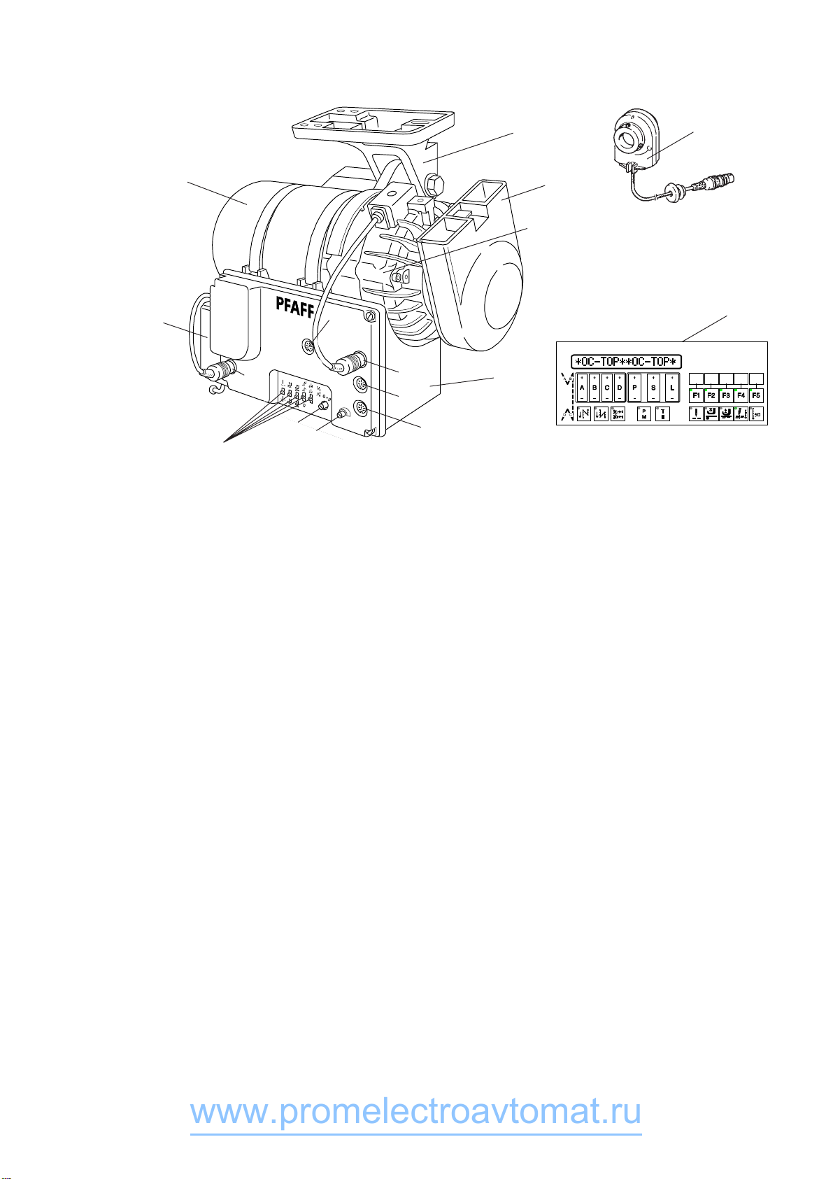
7. Description of the Drive System
Fig. 7.1
The Quick Electronic Stop drive system digital K2 comprises the following main assemblies (see Fig.
7.1):
- Basic motor 1 (asynchronous motor with mounting base 2, solenoid friction clutch/brake unit 3 and
belt guard 4)
- Control system 5
- Speed control unit 6 (command unit)
- Synchronizer 7 (position control unit)
- Operator panel 8 (optional)
7.1 Basic Motor (QD55x, QE55x)
The basic motor is an asynchronous motor with flange-mounted solenoid-controlled friction clutch and
brake unit. The motor is equipped with a terminal box for connection to mains power (mains voltage)
and for connection of the control system to power supply. The rated power of the motor (power at output
shaft P2) is 550 Watt in operating mode S6.
The clutch and brake unit is connected to the front of the control box by means of a 4-lead cable with a
4-contact plug to be inserted into the socket identified by the appropriate symbol (X8).
140896
X8
X9
X10
X1
X7
R1
DS
3
4
6
2
1
WS1 - WS5
8
7
5
www.promelectroavtomat.ru

P20K2E7 7.2
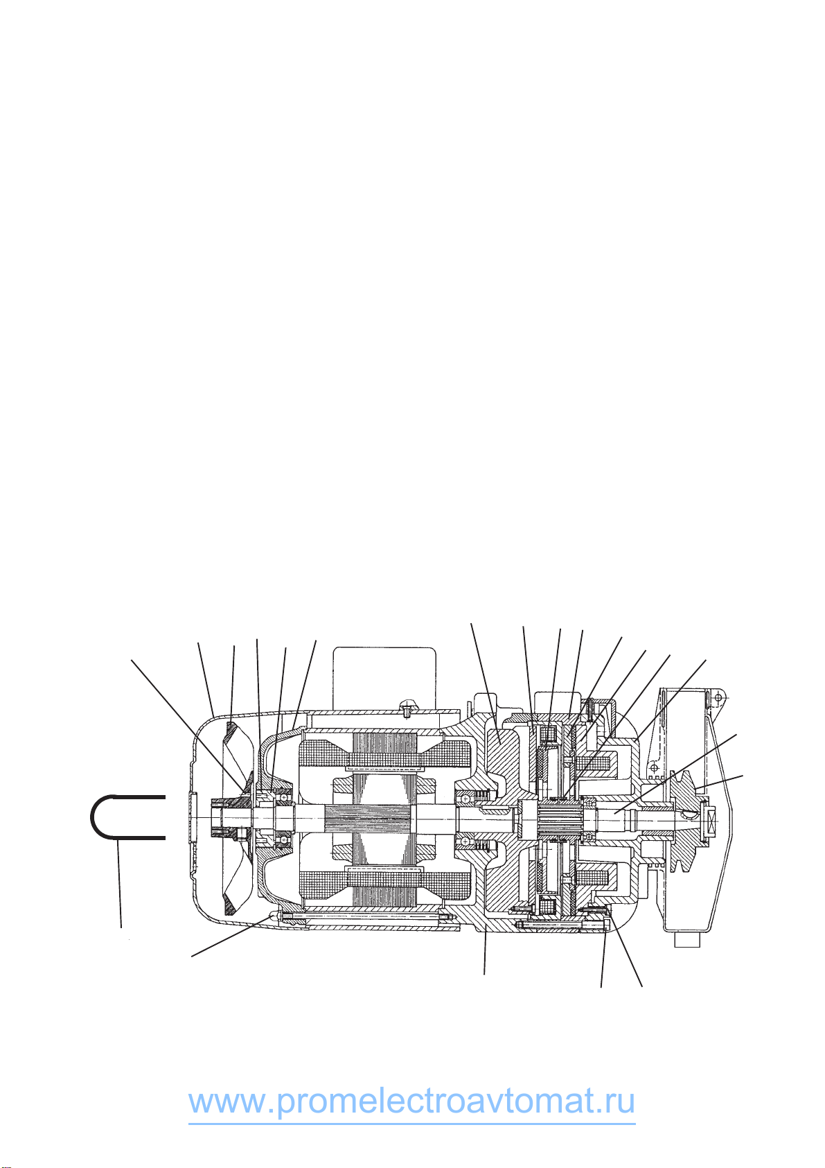
7.1.1 Procedure for Checking and Adjusting the Clutch Clearance
a) Switch the motor off, pull the mains plug out, and wait for the motor to come to complete stop.
b) Take the belt off the belt pulley.
c) Remove fan hood (1) by turning counter-clockwise.
d) Hold the ventilator (2) immobile, and turn belt pulley (10) manually.
If the belt pulley cannot be turned, this means that there is no air gap between the clutch disk (5)
and the flange (7).
e) Loosen the three clamp screws (13) until the belt pulley begins to be turning while the ventilator is
held immobile.
f) Insert adjustment clip (21) into the bores (8) provided on the ventilator (2). Exert pressure on the
adjustment clip (21) and simultaneously turn the ventilator until the adjustment clip snaps into the
bores (9) on the adjustment screw (4).
g) Turn ventilator (2) - with adjustment clip (21) snapped into the adjustment screw (4)- counter-
clockwise about one full turn.
h) Retighten the three clamp screws (13).
i) Turn ventilator (2) - with adjustment clip (21) snapped into the adjustment screw (4) - clockwise
until belt pulley (10) can barely be turned.
j) Turn ventilator (2) - with adjustment clip (21) snapped into the adjustment screw (4) - counter-
clockwise by approx. 120 degrees (120 degrees = distance between two capnuts (11) on the end
bell). After this procedure, the air gap will be approx. 0.5 mm.
k) Remove adjustment clip (21), place fan hood (1) back into position and tighten by turning
clockwise.
Fig. 7.2
8129437
6516 17 19 12
18
14
10
15
13
20
11
21
010895
www.promelectroavtomat.ru

P20K2E7 7.3
7.1.2 Procedure for Replacing of Clutch
a) Switch the motor off, pull the mains plug out, and wait for the motor to come to complete stop.
b) Take the belt off the belt pulley (10).
c) Remove the belt pulley from the shaft.
d) Pull the plug out of socket X8 on the control box.
e) Remove the three screws (13) and pull end bell (12) with clutch/brake assembly off the A end bell
(20) of the motor.
f) Check and clean flange (7).
If the flange shows wear grooves, replace this part.
g) Before placing the new clutch/brake unit, check that the dust washer (not shown in the figure) is
securely seated in the central bore of flange (7).
h) Place the new clutch/brake unit on to the A end bell (20) of the motor and fasten by means of the
three screws (13)
i) Mount the belt pulley.
Put the belt in place and insert the connecting plug of the clutch/brake unit into socket X8 on the
control box.
7.1.3 Procedure for Replacing the Clutch and Brake Disk
a) Proceed as described under 7.1.2, Steps a) through g).
b) Slide clutch disk (5) off the gearing on the output shaft (14).
c) Separate clutch solenoid body (16) from end bell (12) so as to allow brake disk (17) to be removed
from the gearing on output shaft (14).
d) Clean the brake face of brake solenoid body (18).
e) Clean the gearing on output shaft (14) and slide new brake disk (17) on.
f) Slide stop washer (19) with its grease-filled side onto the brake disk hub.
g) Slide new clutch disk (5) onto the gearing of output shaft (14) and press stop washer (19) in.
h) Slide clutch solenoid body (16) onto end bell (12). Make sure that the plug on the end bell is
correctly inserted into the socket on the clutch solenoid body.
i) Place the clutch/brake unit on to the A end bell (20) of the motor and fasten by means of the three
screws (13)
j) Mount the belt pulley.
Put the belt in place and insert the connecting plug of the clutch/brake unit into socket X8 on the
control box.
010895
www.promelectroavtomat.ru

P20K2E7 7.4
7.2 Control System - Control Box
The control box is mechanically attached to the motor casing by means of two retaining straps. The
control system includes two fuses (800 mA slow-action), the power supply transformer, the circuit board
with power supply unit and the electronic control and data processing systems. This circuit board is
accommodated behind the cover closing the box at the front.
Power supply for the control system is derived from the motor terminal box.
The control system P20K2 comprises
sockets X1 for control signals (outputs Ax for connection of solenoids, solenoid valves)
X7 for the speed control unit (command unit)
X8 for the clutch and brake
X9 for the synchronizer (position control unit)
X10 for an operator panel
selectors WS1 for the needle position at sewing stop (down, up)
WS2 to WS5 not used
potentiometer R1 for continuous reduction of the maximum machine speed preset by
parameter <607>.
rotary switch DS for programming the needle positions NPx
outputs (Ax) for connecting solenoids, solenoid valves, signal transmitters etc.
A1: thread trimmer pneumatic
A2: thread trimmer magnetic
140896
www.promelectroavtomat.ru

P20K2E7 7.5
7.3 Speed Control Unit (Command Unit)
As a general rule, this unit is attached to the lefthand side of the control box by means of two screws
and is mechanically connected by means of a pitman rod with the treadle located on the sewing
machine stand.
Electrical connection is made by inserting the cable with 7-contact plug into the correspondingly marked
female connector (X7) located on the lefthand front face of the control box.
The speed control unit is a mecano-electric converter, dividing the treadle stroke into 16 different digital
values comprising 4 bits each.
To achieve this, the speed control unit is equipped with 4 signal tracks (A, B, C, D).
The 16 digital values are listed below together with the treadle stroke (treadle position) and with the
uppertaining command.
Coding Chart of the Speed Control Unit:
Position: Outputs:
ABCD
-2 0110Treadle heeled fully (seam end, SN)
-1 0111Treadle heeled slightly (PF lift)
0 1111Treadle zero position
+1 1110Treadle toed slightly (PF down)
+2 1100Speed step 1
+3 1101Speed step 2
+4 1001Speed step 3
+5 1000Speed step 4
+6 1010Speed step 5
+7 1011Speed step 6
+8 0011Speed step 7
+9 0010Speed step 8
+10 0000Speed step 9
+11 0001Speed step 10
+12 0101Speed step 11
+13 0100Speed step 12 (n-max treadle toed fully)
7.4 Synchronizer (Position Control Unit)
This unit is mechanically attached to the machine handwheel and is connected with the righthand front
face of the control box by inserting a cable with a 6-contact plug into the female connector (X9) marked
with the synchronizer symbol.
The synchronizer is a mechano-electric transducer (angular position transmitter) comprising a
transmitter disk equipped with a signal track and a synchronization track. Signal generation is
performed by photoelectric means via light barriers.
The signal track furnishes 480 pulses per revolution on two channels (FA, FB). The two pulse
sequences are electrically phase-shifted by 90 degrees and thus permit recognition of the direction of
rotation. The synchronization track furnishes one pulse per revolution having a width of 240 pulses
furnished by the signal track.
The synchronizer is a precision instrument. To prevent malfunction, please do not open the
unit!
Synchronization of the drive system and the machine is made with the synchronizer by a teach-in
process within user programming (zero adjustment of the machine).
010895
www.promelectroavtomat.ru

P20K2E7 7.6
7.5 Operator Panel OC-TOP
Fig. 7.3
The operator panel OC-TOP (Fig. 7.3) has the following components:
- a display: 16-digit LCD matrix
- 14 programming keys:
A+ / A-, B+ / B-, C+ / C-, D+ / D-, P+ / P-, S+ / S-, L+ / L-
- 2 keys for operating mode selection:
T9 (P/M) for change-over between programmed or manual sewing
T10 (T/E) for change-over between programming or sewing
- 8 keys with specified functional contents:
T6 for front backtack (on/off)
T7 for end beacktack (of/off)
T8 for backtack inversion
T11 for needle position at sewing stop (up/down)
T12 for presser foot position at sewing stop (up/down)
T13 for presser foot position after seam end (up/down)
T14 for thread trimming (on/off)
T15 for sewing with light barrier (on/off)
- 5 keys (T1 ... T5) with their functional signification being specified by the control program (control
software)
T1 (F1) for linking seam sections (with/without)
T2 (F2) for speed control
constant (automatic) or
variable (treadle-controlled)
T3 (F3) for mirror-image program (with/without)
T4 (F4) speed for treadle-controlled sewing (according to display or acording to <607>)
T5 (F5) currently without function
- outlet for two light barriers on the rear of the OC-TOP
The keys T1 ... T15 are provided with one signal lamp each (LED). Each LED provides optical feedback
on the control position of the function assigned to each key. If the function is ON, the LED is bright; if
the function is OFF, the LED is dark.
140896
www.promelectroavtomat.ru

P20K2E8 8.1
8. Application
The digital K2 drive model X20K2 (X = the supplier of the sewing machine head) can be used either
with or without an operator’s control panel (OCP).
The following operator’s control panels can be used: - OCP B2
-OCP OC-TOP
8.1 Sewing without an Operator’s Control Panel
When working with the X20K2 without operator's control panel, the function switch WS1 on the front of
the control box front is active.
With this switch the following function can be selected:
WS1: Needle position (up/down) when stopping before seam end
8.2 Sewing with Operator’s Control Panel B2
Fig. 8.1
In the event that the digital K2 is used with OCP B2, the following functions can be selected via the
switches of the OCP B2
T1: Needle position when the machine stopped before end of the seam
up: (LED switched on)
down:(LED switched off)
T4: Needle up without trimming
T8: Single stitch: When this key is pressed, the machine will perform one extra stitch.
The switches T2, T3, T5, T6 and T7 are not used here
The actual position of each function is indicated by the LEDs which are built into each key.
Indication of defective functions at the OCP B2:
Functions that are inoperative or defective in the drive or only in the control box will be indicated via the
LEDs in the keys.
There are two signal positions which indicate these malfunctions:
1.) The upper three LEDs and the lower three LEDs are blinking alternately; this means that
the malfunction is within the scope of error codes < 63 (for details see chapter 8.4).
2.) All six LEDs are blinking at the same time; this means that
the malfunction is within the scope of error codes > 64 (for details see chapter 8.4).
T1 T2 T3 T4
T6T5 T7 T8
140896
www.promelectroavtomat.ru

P20K2E8 8.2
8.3 Sewing with External Operator's Control Panel OC-TOP
If an OCP OC-TOP is connected, then the function selection switch WS1 (needle position when the
machine is stopped) is not used.
This function is obtained via OCP switch T6.
Only manual sewing is possible.
Condition: key T9 (P/M) is dark
key T10 (T/E) is dark
Display showing
- before start or after start, when <605> = II
Display showing
- before start, when <605> = I
8.4 Error Messages (Malfunction Diagnostics)
The control system of the drive cyclically tests its own functional condition and the functional condition of
the complete drive system.
Malfunctions are signalled via the display of the external operator panel, for instance:
List of possible error codes:
1Treadle not in zero position when mains power is turned ON
9Start lock
10 Machine class, <799> was changed; remedy: turn mains power switch OFF and ON again
62 Short circuit on 24 V (32 V) DC
63 Overload on 24 V (32 V) DC, load current > 4 amps
64 Power supply monitor: voltage too low (90 V - 150 V)
65 Power electronics not operational after mains power ON, mains power < 130 V
66 Earth short (motor or motor supply line has earth short in one or more phases)
67 Internal malfunction
68 Power electronics shut-off
a) Overcurrent, short circuit in motor or supply line
b) Overvoltage, mains voltage too high (>300 V), motor overloaded while decelerating
c) Undervoltage
69 Synchronizer not furnishing increments
a) Synchronizer plug not inserted
b) Belt not in place or belt tension insufficient
140896
0/0
4160Q0/0
actual speed
symbol for actual
speed
ERROR 7 1
www.promelectroavtomat.ru

P20K2E8 8.3
70 Machine blocked, no increment from synchronizer at max. motor torque
71 Commutation transmitter plug not inserted
72 Synchronizer plugged into commutation transmitter connector
73 Motor overloaded
75 Internal malfunction
90 EEPROM does not exist
91 EEPROM not programmable
92 Start lock while motor running
100-Internal malfunction
117
In case of error messages ≥≥
≥≥
≥ 62, the motor will stop in undefined positions.
Control system reset possible only by mains power OFF/ON.
140896
www.promelectroavtomat.ru

P20K2E9 9.1
9. Programming by the User
Enables machine functions and parameters to be switched on or set up.
User programming of the digital K2 can be carried out via
- operator's control panel OC-TOP
The user programming of the digital K2 is possible by means of an operator's control panel via
- programming parameters.
The programming of parameters is possible via three levels of program:
- Programming on level A (operator level)
- Programming on level B (technician’s level)
- Programming on level C (special level)
9.1 User Programming with Operator Panel OC-TOP
(see fig. 9.1)
Fig. 9.1
140896
0/0
www.promelectroavtomat.ru

P20K2E9 9.2
9.1.1 Programming Level A (Operator Level)
This level is used for programming control parameters which immediately affect the operation
sequence.
This is the parameter for the following function:
- Softstart <116>
a) Activation of Programming Level A
Conditions
Mains power switch ON
Drive system not running
Operating mode: manual sewing must be ON (key T9 (P/M) dark)
Press key T10 (T/E)
Response:
Key T10 (T/E) becomes bright, the display shows in its righthand half the first parameter (parameter no.
and parameter value) associated with programming level A.
Sewing is not possible
- Programming
The Parameter number is set by using keys P+ or P- (hundreds of parameter no.) and keys S+ or
S- (tens and units of parameter no.). The parameter value is programmed by using key L+ or L-
b) Deactivation of the Programming Level A
Press key T10 (T/E)
Respose:
Key T10 (T/E) goes dark, the display returns to initial condition.
Sewing is possible.
0/0
1 16 3
140896
0/0
www.promelectroavtomat.ru

P20K2E9 9.3
9.1.2 Programming Level B (Technician Level)
This level is used for programming the control parameters which have to be modified or adapted very
rarely or only for starting operation of the system.
a) Preparation for activation of the programming level B
Turn mains power switch OFF
Press and hold keys T9 (P/M) and T10 (T/E) simultaneously
Turn mains power switch ON
Release keys
Response:
The display shows a „Q“.
Sewing is possible.
b) Activation of programming level B
Press key T9 (P/M) (not becoming bright) and press key T10 (T/E) (becoming bright)
Response:
In the righthand half of the display are shown: a parameter number (at first 116, then the number
selected last) and the associated value.
Sewing is not possible.
Modification of parameter number:
for hundreds of parameter numbers use key P+ or P-
for tens and units of parameter numbers use key S+ or S-
Modification of parameter value: via key L+ or L-
c) Deactivation of progrmming level B
Press key T10 (T/E) (not becoming bright)
Response:
Parameters shown disappear from the display, the display returns to initial condition
Sewing is posssible.
0
Q
0
116 0
140896
0
Q
0
www.promelectroavtomat.ru

P20K2E9 9.4
9.1.3 Programming Level C (Special Level)
At this level, control parameters are stored the values of which have to be modified in exceptional
cases only. Correction of these parameters should therefore be made only after consultation of the
manufacturer.
Activation of programming level C
a) Activate programming level B (see 9.1.2)
b) Call up parameter 798
c) Set parameter value <798> to I
d) Deactivate programming level B
e) Turn mains power switch OFF, wait for >2 secs. to elapse
f) Turn mains power switch back ON
g) Press key T10 (T/E) (becoming bright)
Response:
In the righthand half of the display appears the first parameter of programming level C.
Calling up further parameter numbers and correcting the parameter values can be made in the same
way as described for programming levels A and B.
Deactivation of programming level C:
- Press key T10 (T/E) (not becoming bright)
- Turn mains power switch OFF
9.1.4 Reset
All parameter values having been modified from the ex-factory condition (standard value) are reset to
their standard values by this procedure.
Exceptions: parameters 700 and 799
For these parameters, the values programmed by the user are retained even after -
Reset- has been performed.
-Reset- procedure:
- turn mains power switch OFF
- press treadle fully forward and hold in that position
- press and hold keys P- or P+, S- or S+ and L- or L+ simultaneously
140896
www.promelectroavtomat.ru

P20K2E9 9.5
- turn mains power switch ON
- relese the three keys and the treadle
Response: Display showing
Now -Reset- can be performed.
Located below the disply Y (yes) there is key P+. Press this key P+ to start the reset. The display briefly
shows:
After that the display shows the power-on display for approx. 2 secs.
and then shows the display corresponding to the operating mode selected
If it is not desired to start the -Reset-, press key L+ located below the display saying N (no).
RESE T Y - - N
MASTE R-RE SET
X20K2 4 Z-001
-X
0/0
140896
www.promelectroavtomat.ru

P20K2E9 9.6
9.2 User Programming without Operator Panel
To a limited extent, programming of the control system is also possible without an operator panel. This
is done by means of internal miniature switches MS (S1a, S1b, S1c and S1d) and of the rotary switch
DS accommodated on the control circuit board. The switches (S1a, S1b, S1c, S1d) are accessible when
the front cover of the control box is removed.
9.2.1 Needle Positions NPx
Turn switch S1a on
Use rotary switch DS (S2) to select the different needle positions (NPx):
Switch Position Meaning
1 NP0: zero/reference position of the needle, <700>
2 NP1: needle down <702>
3 NP2: thread takeup lever up, <703>
4 NP5: end of trimming signal 1, <705>
5 NP6: start of trimming signal 2, <706>
Toe the treadle to open the programming mode. Turn the handwheel to correct (modify) the positions.
Store the last position setting by advancing switch S2 or by turning S1a off.
For needle positions 5 (end of trimming signal 1) and 6 (start of trimming signal 2), the position settings
can also be stored by heeling the treadle. This will cause the machine to run into NP2.
Heeling the treadle once more will cause the machine to make a full revolution with a trimming process
being performed.
This can be repeated and thus permits easy checking of the trimming process.
9.2.2 Maximum Speed (<607>)
-Turn switches S1a and S1b on
- Toe treadle fully and hold in that position.
Response: speed is at first reduced to 500 rpm and is then increased in 300 ms intervals by 100
rpm increments.
- Finalize the adjustment and store the value obtained by leaving the treadle end position.
- This can be repeated by toeing the treadle again into its end position.
9.2.3 Standstill Brake (Residual Brake <718>)
Turn switch S1d on; this enables the standstill brake at a fixed value (<718>).
The standstill brake can be disabled by turning switch S1d off.
9.2.4 Reset
- Switch the drive system off.
- Turn switch S1a on
- Toe the treadle to its end position and switch the drive system on.
Result: all parameter values have been reset to their standard values (initial values), with the
exception of NP0 (<700>).
140896
www.promelectroavtomat.ru

P20K2E10 10.1
10. Start of Operation
If the digital K2 has been stored at a temperature of <+5°C, then a working temperature of between +5°C
and +40°C must first be obtained. The equipment must be dry.
Before work with the machine can be started, make sure to perform the following:
a) Control the direction of rotation
b) Adjust the reference position of the needle bar
c) Control the needle positions
d) Control the maximum speed
10.1 Start of the Operation without the Operator’s Control Panel
10.1.1 Procedure for Checking the Direction of Rotation and for the correct Adjustment of the Needle
Bar (Reference Position NP0)
(see also 9.2.1)
a) Switch machine ON and actuate treadle briefly forward.
Response: machine starts running briefly
b) Is the direction of rotation correct?
If yes, proceed to adjust the zero position, continue with c)
If no, switch the drive system off, pull the mains plug out, and change two connections in the motor
terminal box.
For QDx, interchange connections L1 and L2;
for QEx, move capacitor lead from contact 1 to contact 3.
After that, continue with a)
c) Remove front cover of the control box, turn miniature switch S1a ON; turn rotary switch DS into
position 1
d) Actuate treadle briefly forward
Response: machine makes one full revolution and positions at random.
e) Adjust the zero position of the needle bar by turning the machine handwheel in the direction of
rotation until the needle tip on its way down reaches the needle plate level (reference position).
f) Toe treadle briefly
Response: machine makes a full revolution and positions in the same position that has been
adjusted manually before
g) The reference position is stored when either S1a is switched OFF or rotary switch DS is turned to a
different position.
10.1.2 Control of the Needle Positions (NP1 / NP2)
(see also 9.2.1)
NP1 - needle down position <702>
NP2 - thread take up lever in the up position <703>
a) Remove front cover of the control box, turn miniature switch S1a ON; turn rotary switch DS into
position 2
b) Actuate treadle briefly forward
Response: machine starts and positions in position 1
c) Is the needle position correct?
When yes, then proceed as with f) below.
When no, then the position must be changed by turning the handwheel
140896
www.promelectroavtomat.ru

P20K2E10 10.2
d) Actuate the treadle briefly forward
Reaction: The machine performs a revolution and positions in the same position.
e) The position can again be corrected.
When no further correction is needed, then proceed as with f) below.
f) The selected needle position is stored when either S1a is switched OFF or rotary switch DS is turned
to a different position.
g) Remove front cover of the control box, turn miniature switch S1a ON; turn rotary switch DS into
position 3
h) Actuate treadle briefly forward
Response: machine starts and positions in position 2
i) Is the needle position correct?
When yes, then proceed as with f) below.
When no, then the position must be changed by turning the handwheel
j) Actuate the treadle briefly forward
Reaction: The machine performs a revolution and positions in the same position.
k) The position can again be corrected.
When no further correction is needed, then proceed as with f) below.
10.1.3 Control of the Positioning (Angle) for Thread Trimming (NP5 / NP6) (see also 9.2.1)
NP5 - end of trimming signal 1 (<705>)
NP6 - start of trimming signal 2 (<706>)
a) Remove front cover of the control box, turn miniature switch S1a ON; turn rotary switch DS into
position 4
b) Actuate treadle briefly forward
Response: machine starts and positions in position 4
c) Is the needle position correct?
When yes, then proceed as with f) below.
When no, then the position must be changed by turning the handwheel
d) Actuate the treadle briefly forward
Reaction: The machine performs a revolution and positions in the same position.
e) The position can again be corrected.
If no further correction is needed, then proceed as f) below.
f) The selected needle position is stored when either S1a is switched OFF or rotary switch DS is turned
to a different position.
g) Remove front cover of the control box, turn miniature switch S1a ON; turn rotary switch DS into
position 5
h) Actuate treadle briefly forward
Response: machine starts and positions in position 5
i) Is the needle position correct?
When yes, then proceed as with f) below.
When no, then the position must be changed by turning the handwheel
j) Actuate the treadle briefly forward
Reaction: The machine performs a revolution and positions in the same position.
k) The position can again be corrected.
If no further correction is needed, then proceed as f) below.
140896
www.promelectroavtomat.ru
This manual suits for next models
1
Table of contents
Other promelectroavtomat Sewing Machine manuals
Popular Sewing Machine manuals by other brands

DURKOPP ADLER
DURKOPP ADLER M-Type Delta D867 Service instructions

KANSAI SPECIAL
KANSAI SPECIAL DVK1702B Instruction

IMER
IMER COMBI 350/600 Operating, maintenance, spare parts manual

DURKOPP ADLER
DURKOPP ADLER 1183I brochure

Singer
Singer 146-30 Instructions for installing and using

Singer
Singer Simple 3221 brochure