Pfaff 1163 Guide

This Adjustment Manual is valid for machines from the
following serial numbers onwards:
# 6001000
Adjustment Manual
1163
296-12-18 710/002
Justieranleitung engl. 06.04

The reprinting, copying or translation of PFAFF Service Manuals, whether in whole or in part,
is only permitted with our previous authorization and with written reference to the source.
PFAFF Industrie Maschinen AG
Postfach 3020
D-67653 Kaiserslautern
Königstr. 154
D-67655 Kaiserslautern

Contents
Contents ................................................................................. Chapter - Page
13 Adjustment ................................................................................................................ 13 - 1
13.01 Notes on adjustment................................................................................................... 13 - 1
13.02 Tools, gauges and other accessories .......................................................................... 13 - 1
13.03 Abbreviations .............................................................................................................. 13- 1
13.04 Adjusting the basic machine ....................................................................................... 13 - 2
13.04.01 Pre-adjusting the needle height................................................................................... 13 - 2
13.04.02 Setting the bottom feed dog at its neutral position ..................................................... 13 - 3
13.04.03 Bottom feed dog motion............................................................................................ 13 - 4
13.04.04 Bottom feed dog position............................................................................................ 13 - 5
13.04.05 Needle rise, hook clearance, needle height and bobbin case position finger............... 13 - 6
13.04.06 Thread check spring and thread regulator ................................................................... 13 - 7
13.04.07 Knee lever stop ...........................................................................................................13- 8
13.04.08 Presser foot pressure ................................................................................................. 13 - 9
13.05 Adjusting the thread trimmer –900/93......................................................................... 13 -10
13.05.01 Adjusting the synchronizer.......................................................................................... 13 -10
13.05.02 Adjusting the control cam ........................................................................................... 13 -11
13.05.03 Position of the stationary knife.................................................................................... 13 -12
13.05.04 Needle thread tension release .................................................................................... 13 -13
13.06 Adjusting the thread wiper –909/93 ............................................................................ 13 -14
13.07 Adjusting the automatic presser foot lift –910/93........................................................ 13 -15
13.08 Adjusting the backtacking mechanism –911/93 .......................................................... 13 -16
13.09 Parameter settings...................................................................................................... 13 -17

Contents
Contents ................................................................................. Chapter - Page
13.09.01 Selecting the user level ............................................................................................... 13 -17
13.09.02 Example of a parameter input ..................................................................................... 13 -18
13.09.03 Liste der Parameter .................................................................................................... 13 -19
13.10 Reset / Cold start ........................................................................................................ 13 -20
13.11 Explanation of the error signals ................................................................................... 13 -21
13.13 Internet update of the machine software.................................................................... 13 -22

Adjustment
13 - 1
13 Adjustment
Please observe all notes from Chapter 1 Safety of the instruction manual! In
particular care must be taken to see that all protective devices are refitted
properly after adjustment, see Chapter 1.06 Danger warnings of the
instruction manual!
If not otherwise stated, the machine must be disconnected from the electrical
power supply.
13.01 Notes on adjustment
All following adjustments are based on a fully assembled machine and may only be carried
out by expert staff trained for this purpose.
Machine covers, which have to be removed and replaced to carry out checks and
adjustments, are not mentioned in the text.
The order of the following chapters corresponds to the most logical work sequence for
machines which have to be completely adjusted. If only specific individual work steps are
carried out, both the preceding and following chapters must be observed.
Screws, nuts indicated in brackets ( ) are fastenings for machine parts, which must be
loosened before adjustment and tightened again afterwards.
13.02 Tools, gauges and other accessories
●1 set of screwdrivers with blade widths from 2 to 10 mm
●1 set of wrenches with jaw widths from 7 to 14 mm
●1 set of Allan keys from 1.5 to 6 mm
●1 metal ruler, part no. 08-880 218-00
13.03 Abbreviations
t.d.c. = top dead centre
b.d.c. = bottom dead centre

Adjustment
13 - 2
13.04 Adjusting the basic machine
13.04.01 Pre-adjusting the needle height
Requirement
With the needle bar at b.d.c., the top marking on needle bar 1should be level with the
bottomedgeofbushing3.
●By turning the balance wheel, bring the needle bar to its b.d.c.
●Without twisting it, adjust needle bar 1(screw 2) in accordance with the requirement.
9 013
Fig. 13 - 01
2
1
3

Adjustment
13 - 3
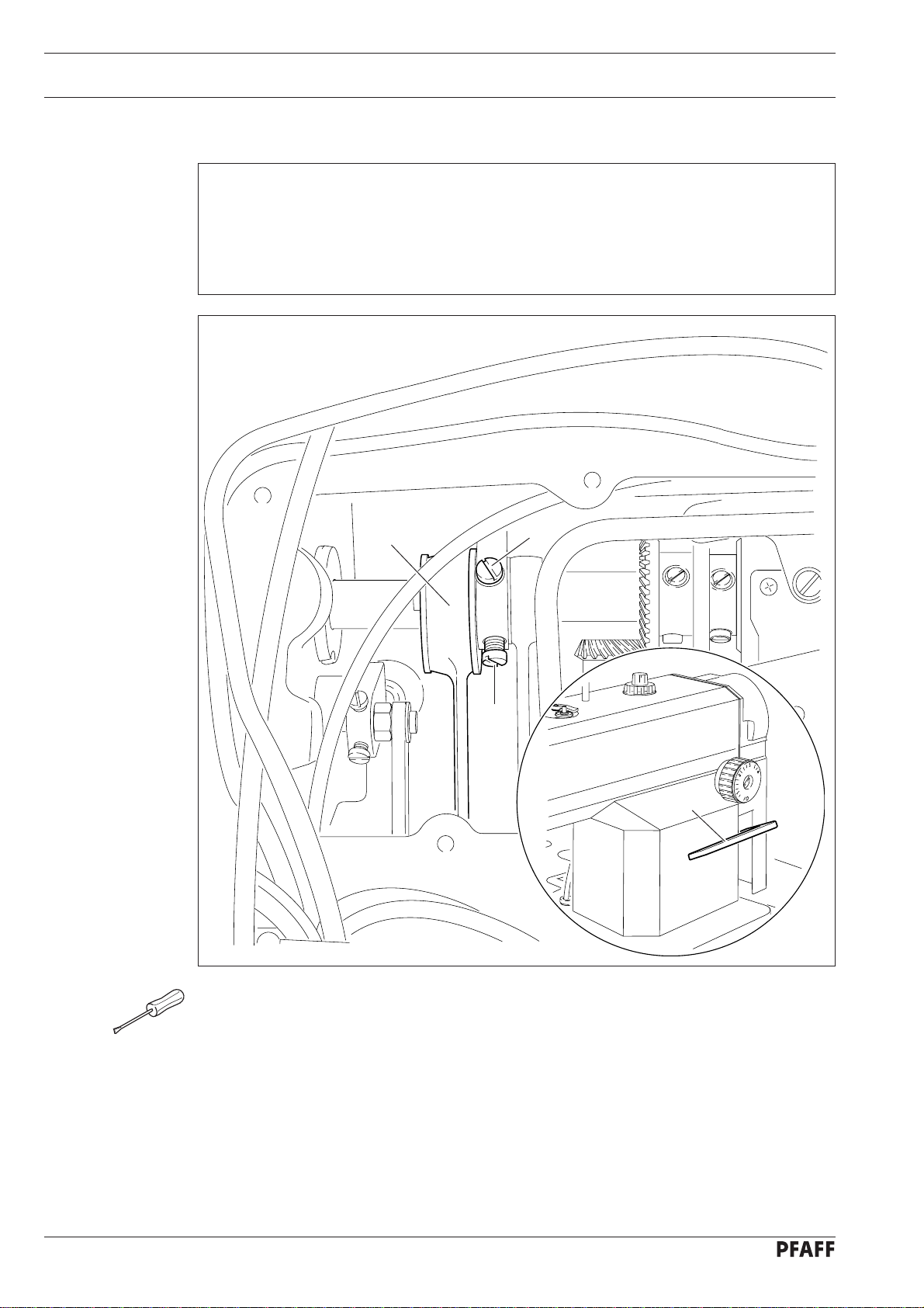
13.04.02 Setting the bottom feed dog at its neutral position
Requirement
With the stitch length set at "0", cranks 1and 3should be in alignment, and there should be
nofeedingmotionofthebottom feed dogwhenthebalancewheelisturned.
Fig. 13 - 02
●Raise the presser foot and set the stitch length at "0".
●Adjust crank 1(screw 2) in accordance with the requirement.
76-026
3
2
1
Adjustment
13 - 4
13.04.03 Bottom feed dog motion
Requirement
1. When the needle bar is at its t.d.c., the bottom feed dog should be in its top point of
reversal when the stitch length is set at "0".
2. When the needle bar is positioned 0.6 after t.d.c. and the largest stitch length is set, the
bottomfeeddog should not move when thereversefeedswitch 3is operated.
●Without moving it sideways, adjust eccentric 1(screws 2) in accordance with the
requirements.
Fig. 13 - 03
76-029
12
2
79-014
3

Adjustment
13 - 5
76
-
028
13.04.04 Bottom feed dog position
Requirement
When the stitch length is set at "0" and the bottom feed dog 5is at t.d.c., it should
1. Bepositionedinthecentreoftheneedleplatecutoutin thefeedingdirection.
2. Its teeth should be 0.75 – 0.85 mm parallel over the needle plate.
Fig. 13 - 04
●Shift or turn crank 1(screw 2) in accordance with requirement 1.
●Turn crank 3(screw 4) in accordance with requirement 2.
4
3
2
1
76-054
5
0,75 - 0,85 mm

Adjustment
13 - 6
13.04.05 Needle rise, hook clearance, needle height and bobbin case position finger
Requirement
When the bottom marking on needle bar 3is level with the bottom edge of bushing 5
1. The point of hook 1should be centred to the needle and at a distance of 0.04 – 0.10 mm
fromthegrooveoftheneedle,and
2. Thetopedgeof the needle eye shouldbe0.8mmbelowthe hook point.
●Adjust the hook 1(screws 2) in accordance with requirement 1.
●Without twisting needle bar 3(screw 4), adjust it according to requirement 2.
9
-013
0,8 mm
3
5
4
76-031
0,04 - 0,10 mm
1
2
Fig. 13 - 05
Other manuals for 1163
2
Table of contents
Other Pfaff Sewing Machine manuals

Pfaff
Pfaff CREATIVE 4.0 - Quick start guide

Pfaff
Pfaff 130-6 User manual

Pfaff
Pfaff Hobbylock 784 User manual

Pfaff
Pfaff Sewing Machine Guide

Pfaff
Pfaff hobby 1132 User manual

Pfaff
Pfaff hobbylock 2.5 User manual

Pfaff
Pfaff 1571 User manual

Pfaff
Pfaff Embroidery Mode-Stitch-Out User manual

Pfaff
Pfaff 1025 User manual

Pfaff
Pfaff expression 150 User manual

Pfaff
Pfaff 1211 User manual

Pfaff
Pfaff Quilt Expressions 4.0 User manual

Pfaff
Pfaff 3371-1 series User manual

Pfaff
Pfaff hobbyblock 756 User manual

Pfaff
Pfaff 335 Guide

Pfaff
Pfaff 141 User manual

Pfaff
Pfaff 1163 User manual

Pfaff
Pfaff 145 User manual

Pfaff
Pfaff 3371-10 series User manual

Pfaff
Pfaff Embroidery Machines User manual


