Promotech BM-21S User manual


Contents
1. GENERAL INFORMATION............................................................................................... 3
1.1. Application................................................................................................................. 3
1.2. Technical data............................................................................................................ 3
1.3. Design ....................................................................................................................... 5
1.4. Equipment included ................................................................................................... 5
2. SAFETY PRECAUTIONS.................................................................................................. 6
3. STARTUP AND OPERATION........................................................................................... 8
3.1. Preparing................................................................................................................... 8
3.1.1. Adjusting the bevel angle and width................................................................. 8
3.1.2. Using cutting fluid............................................................................................ 9
3.2. Adapting for 150–300 mm pipes ...............................................................................10
3.3. Adapting for 300–600 mm pipes (requires optional equipment).................................13
3.4. Operating..................................................................................................................14
3.5. Replacing the cutting inserts.....................................................................................16
3.6. Replacing the milling head........................................................................................17
4. WIRING DIAGRAM..........................................................................................................18
5. SPARE AND WEARING PARTS......................................................................................19
6. DECLARATION OF CONFORMITY.................................................................................20
7. QUALITY CERTIFICATE..................................................................................................21
8. WARRANTY CARD..........................................................................................................22
BM-21S
This document is protected by copyrights.
Copying, using, or distributing without permission of PROMOTECH is prohibited.
3
1. GENERAL INFORMATION
1.1. Application
The BM-21S is abevellingmachine designed to bevel materials made of stainless steel.
The machine can bevel plates, as well as pipes with outer diameters of 150–300 mm
(6–12’’), at an angle of 0–60° and with the bevel width of up to 21 mm (13/16’’).
Additionally, the machine contains dampers to reduce vibrations.
When equipped with an optional guide, the machine can bevel pipes with outer
diameters of 300–600 mm (12–24’’).
1.2. Technical data
Voltage
1~ 220–240 V, 50–60 Hz
1~ 110–120 V, 50–60 Hz
Power
1600 W (for 50 Hz)
1800 W (for 60 Hz)
Rotational speed
1360–1630 rpm (at 230 V)
1300–1560 rpm (at 115 V)
Protection level
IP 20
Protection class
I
Milling speed
270 m/min (900 ft/min, for 50 Hz)
320 m/min (1050 ft/min, for 60 Hz)
Maximum bevel width (b)
21 mm (13/16’’, Fig. 1)
Bevel angle (ß)
0–60° (Fig. 1)
Weight
23 kg (51 lbs)
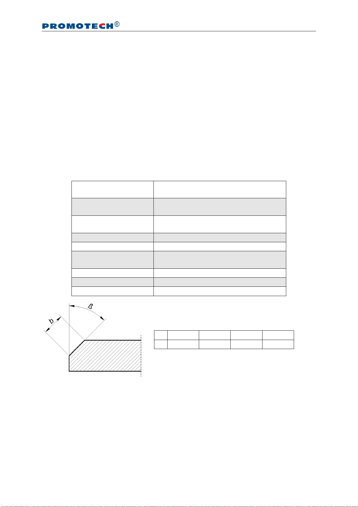
Fig. 1. Bevel dimensions; maximum bevel width depending on the angle
β
0°
30°
45°
60°
b
21 mm
18.5 mm
21 mm
18.5 mm
BM-21S
This document is protected by copyrights.
Copying, using, or distributing without permission of PROMOTECH is prohibited.
4
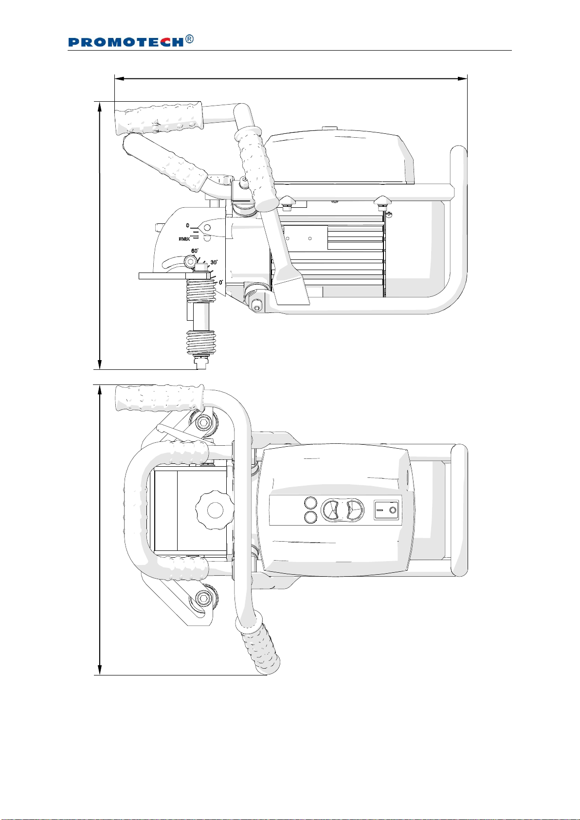
441 mm (17.4’’)
339 mm (13.4’’)
366 mm (14.4’’)
BM-21S
This document is protected by copyrights.
Copying, using, or distributing without permission of PROMOTECH is prohibited.
5
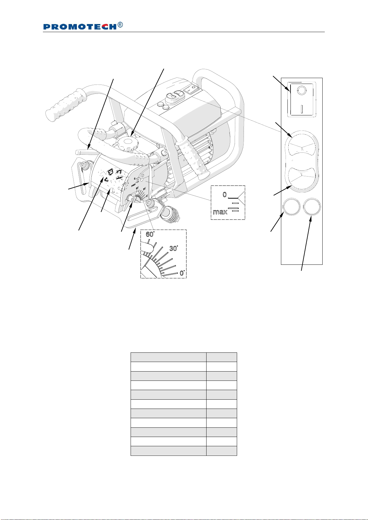
1.3. Design
Fig. 2. View of the machine and the control panel
1.4. Equipment included
The BM-21Sis supplied in ametal box with complete standard equipment. The included
equipment consists of:
Bevelling machine
1 unit
Cutting insert
10 units
Metal box
1 unit
8 mm hex wrench
1 unit
6 mm hex wrench
1 unit
4 mm hex wrench
1 unit
12 mm flat wrench
1 unit
T15P torx screwdriver
1 unit
Oil for stainless steel
1 unit
Grease for screws
1 unit
Operator’s Manual
1 unit
Depth knob
Bevel width scale
Bevel angle scale
Screws locking the bevel angle
Depth lock lever
Power switch
START
STOP
Operating
mode
lamp
Overload lamp
Guide set
Milling
head
Milling
head
cover

BM-21S
This document is protected by copyrights.
Copying, using, or distributing without permission of PROMOTECH is prohibited.
6
2. SAFETY PRECAUTIONS
1. Before beginning, read this Operator’s Manual and complete proper occupational
safety and health training.
2. The machine must be used only in applications specified in this Operator’s Manual.
3. The machine must be complete and all parts must be genuine and fully operational.
4. Theelectricalsupplyspecificationsmustconformtothosespecifiedontheratingplate.
5. The machine must be plugged into a properly grounded (earthed) socket-outlet.
6. Never pull the power cord because this may damage it and result in electric shock.
7. Untrained bystanders must not be present near the machine.
8. Before beginning, check the condition of the machine and electrical supply, including
the power cord, plug, control panel components, and milling tools.
9. Keep the machine dry. Exposure to rain, snow, or frost is prohibited.
10. Keep the work area well lit, clean, and free of obstacles.
11. Never use machine near flammable liquids or gases, or in explosive environments.
12. Use only tools specified in this Operator’s Manual.
13. Never use dull or damaged tools.
14. Mount the cutting inserts and the milling head securely. Remove adjusting keys
and wrenches from the work area before connecting the plug to the power outlet.
15. If the cutting edge of an insert is worn, rotate the insert in the socket by 90° or, if
all edges are worn, replace with a new insert specified in this Operator’s Manual.
16. Before every use, inspect the machine to ensure it is not damaged. Check whether
any part is cracked or improperly fitted. Make sure to maintain proper conditions
that may affect the operation of the machine.
17. Always use eye and hearing protection, respiratory protective devices, non-skid
footwear, gloves,and protectiveclothingduringoperation.Do not wearlooseclothing.
18. Do not touch moving parts or metal chips formed during milling. Prevent objects
from being caught in moving parts.
19. After every use, remove metal chips from the machine, especially from the milling
head. Never remove metal chips with bare hands. Clean the machine with a cotton
cloth without using any agents.
20. Cover steel parts with a thin anti-corrosion coating to protect the machine from
rust when not in use for any extended period.

BM-21S
This document is protected by copyrights.
Copying, using, or distributing without permission of PROMOTECH is prohibited.
7
21. Maintain the machine and mount/dismount parts and tools only with the power
cord unplugged from the power outlet.
22. Repair only in a service center appointed by the seller.
23. If the machine falls from any height, is wet, or has other damage that could affect
the technical state of the machine, stop the operation and immediately send the
machine to the service center for inspection and repair.
BM-21S
This document is protected by copyrights.
Copying, using, or distributing without permission of PROMOTECH is prohibited.
8
3. STARTUP AND OPERATION
3.1. Preparing
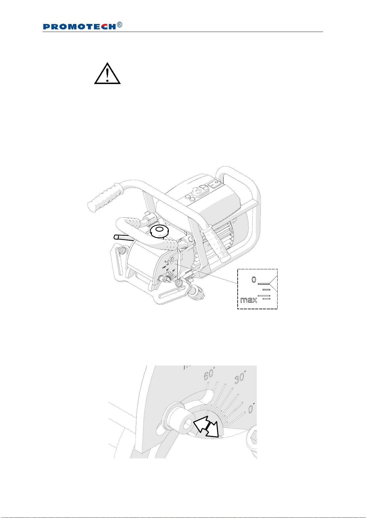
3.1.1.Adjusting the bevel angle and width
Unplug the power cord from the power outlet. Begin with setting the bevel width to
zero. To do this, loosen the lock lever (Fig. 3) and rotate the knob to set the indication
‘0’ on the bevel width scale, and tighten the lever.
Fig. 3. Initial setting the bevel width to zero
To set the required bevel angle (Fig. 4), use the 6 mm hex wrench to loosen two
side screws, rotate the guide set to obtain the required angle on the scale, and tighten
the screws in this new position.
Fig. 4. Setting the bevel angle (45° is set on the drawing)
Adhere to all safety precautions.

BM-21S
This document is protected by copyrights.
Copying, using, or distributing without permission of PROMOTECH is prohibited.
9
After setting the bevel angle, adjust the bevel width using the depth knob. The
width scale provides only a rough value because the bevel width varies with the angle.
For example, for 10° the maximum width b(Fig. 1) is equal about 18 mm (11/16’’),
while the width scale indicates about 9 mm (6/16’’). Increasing the depth at this angle
will distort the bevel. The maximum bevel width (b=21 mm, 13/16’’) is obtained for 45°.
The demanded bevel width for the required angle must be determined experimentally
by gradually increasing the penetration of the milling head into the workpiece.
3.1.2.Using cutting fluid
Before bevelling stainless steel, cover the edges of the workpiece with the supplied
oil in the manner shown in Fig. 5.
Fig. 5. Preparing the edges for bevelling stainless steel
Oil for stainless steel
BM-21S
This document is protected by copyrights.
Copying, using, or distributing without permission of PROMOTECH is prohibited.
10
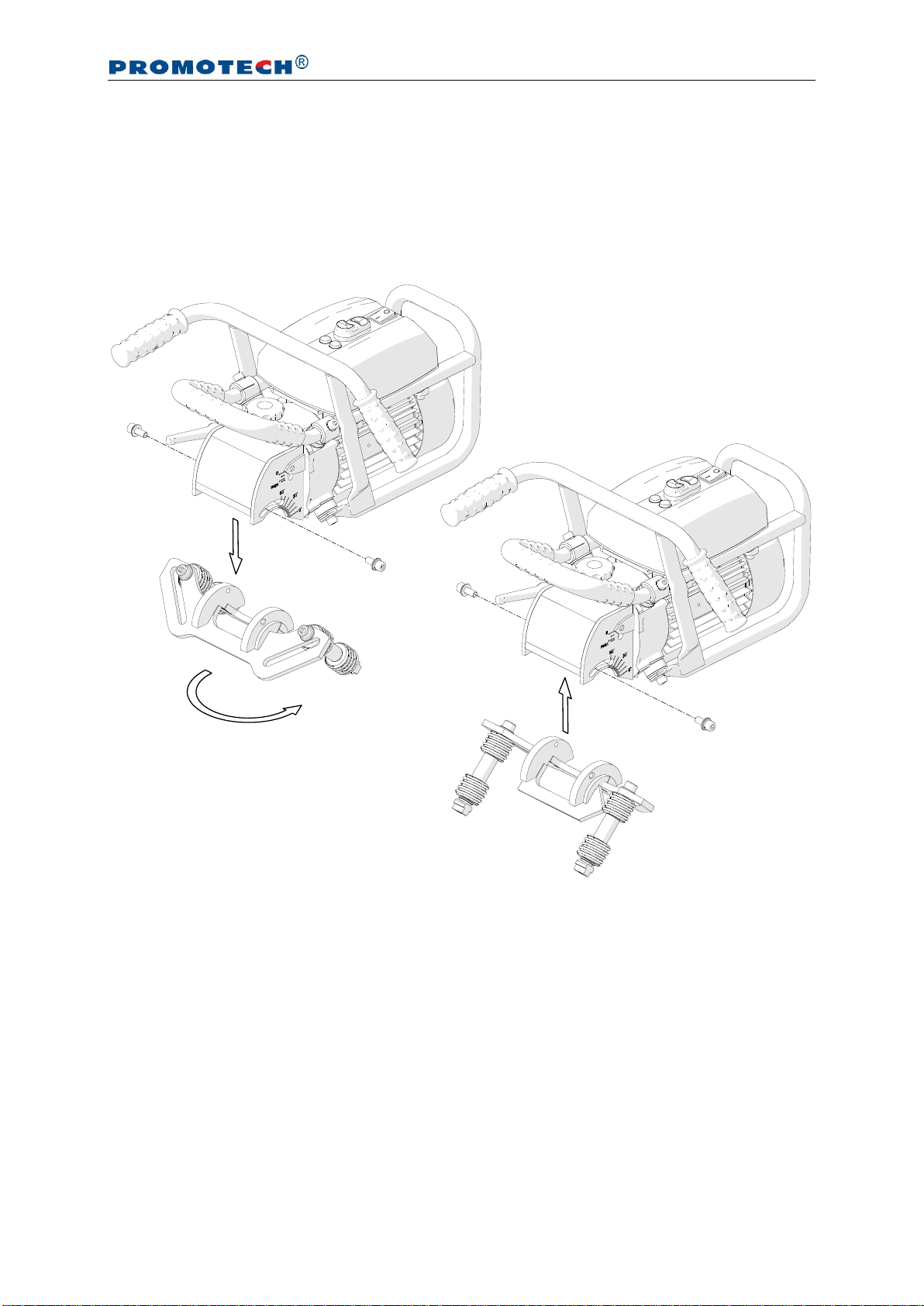
3.2. Adapting for 150–300 mm pipes
To bevel pipes with diameters of 150–300 mm (6–12’’), use the standard guide set
after assembling it in adifferent way. To do this, use the 6 mm hex wrench to unscrew
two side screws (1, Fig. 6), then remove the guide set (2), rotate it by 180° around
the vertical axis (3), mount again (4), and secure with the screws (1).
Fig. 6. Rotating and mounting the guide set
Lock the turn of the T-nut with the 12 mm flat wrench and use the 8 mm hex
wrench to unscrew the roller screw. Next, move the rollers from the opening (Fig. 7a)
to the slot by mounting them as shown in Fig. 7b, placing the T-nut into the slot.
1
2
4
3
1

BM-21S
This document is protected by copyrights.
Copying, using, or distributing without permission of PROMOTECH is prohibited.
11
Fig. 7. Moving the rollers from the opening to the slot
Loosen the depth lock lever (Fig. 8) and rotate the depth knob to set the indication
‘0’ on thebevel width scale.Then,separatetherollersfrom each other as far as possible.
Fig. 8. Initial setting the bevel width to zero and separating the rollers before using the
machine on the pipe
Place the machine on avertically positioned pipe, joining the surfaces of the guide
set to the face and side of the pipe. Then, move the rollers symmetrically to join them
Roller screw
a)
b)

BM-21S
This document is protected by copyrights.
Copying, using, or distributing without permission of PROMOTECH is prohibited.
12
to the pipe (Fig. 9) and tighten using the 8 mm hex wrench in this position. Set the
required bevel angle and width as described before.
Fig. 9. Machine prepared for work on pipes with diameters of 150–300 mm (6–12’’)
BM-21S
This document is protected by copyrights.
Copying, using, or distributing without permission of PROMOTECH is prohibited.
13
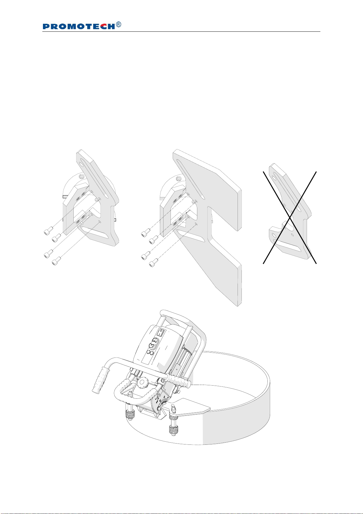
3.3. Adapting for 300–600 mm pipes (requires optional
equipment)
To bevel pipes with diameters of 300–600 mm (10–24’’), assemble the guide set
using an optional guide. To do this, remove the guide set (1, 2, Fig. 6), use the 4 mm
hex wrench to unscrew the standard guide, and assemble the guide for 300–600 mm
pipes (Fig. 10), tightening with the screws. Mount the rollers and adjust the required
bevel angle and width as described before.
Fig. 10. Machine prepared for work on pipes with diameters 300–600 mm
Part number:
PRW-0505-03-00-00-0
BM-21S
This document is protected by copyrights.
Copying, using, or distributing without permission of PROMOTECH is prohibited.
14
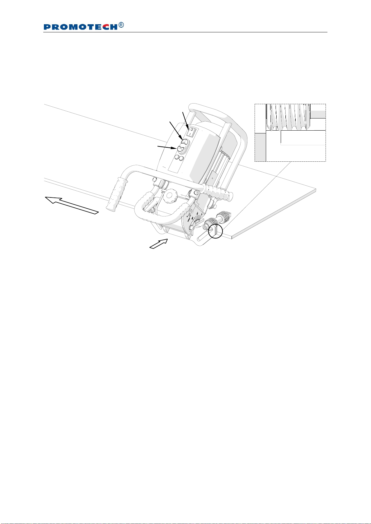
3.4. Operating
After setting the bevel angle and width, connect the machine to a properly grounded
power outlet. Then, place the machine vertically on the right to rest the rollers on the
plate and maintain a gap between the milling head and the plate (Fig. 11).
Fig. 11. Machine properly positioned on the workpiece
Power on the machine by setting the power switch to position ‘I’, and start the motor
using the green START button. Slide the machine toward the plate face and bevel by
sliding the machine to the left, constantly pressing the machine against the workpiece.
Bevelling is performed according to the counter-rotation. The rotation direction of
the milling head is marked on the motor disk under the milling head cover.
The feed rate will depend on the profile and composition of the workpiece.
Most steels capable of being welded can be bevelled in one pass. However, make
bevels wider than 12 mm (1/2’’) in at least two or three passes because this will require
less effort and total time than for bevelling in a single pass.
To obtain the maximum bevel width (21 mm, 13/16’’) in two passes, the bevel
after the first pass should be about 14 mm (9/16’’) wide, while for three passes about
12 mm (1/2’’) wide after the first pass and about 16 mm (5/8’’) after the second one.
If the maximum permitted motor load is exceeded because of, for instance, too
fast feed, the red overload lamp will light. Continuing the operation in such a case will
trigger the safety circuit and shut down the motor. If as a result of an overload the
motor will shut down, separate the machine from the working edge, turn off the power
STOP
Feed direction
Power switch
START
Slide toward after starting the motor

BM-21S
This document is protected by copyrights.
Copying, using, or distributing without permission of PROMOTECH is prohibited.
15
by setting the power switch in position ‘O’, and after the red overload lamp turns off,
power on the machine again.
Operating near the overload (with the red lamp flashing) is allowed; however,
never allow the motor temperature to exceed 85°C (185°F) because this can lead to
damage of the motor windings. After every hour of operating under full load, stop the
motor for 10–15 minutes. Never cool the motor by running without load because it will
become heated even faster than when working with load.
After the work is finished, stop the motor using the STOP button and set the
power switch to the position ‘O’. Use petroleum ether to clean oil from the workpiece.
Clean the machine with a cotton cloth without using any agents.
BM-21S
This document is protected by copyrights.
Copying, using, or distributing without permission of PROMOTECH is prohibited.
16
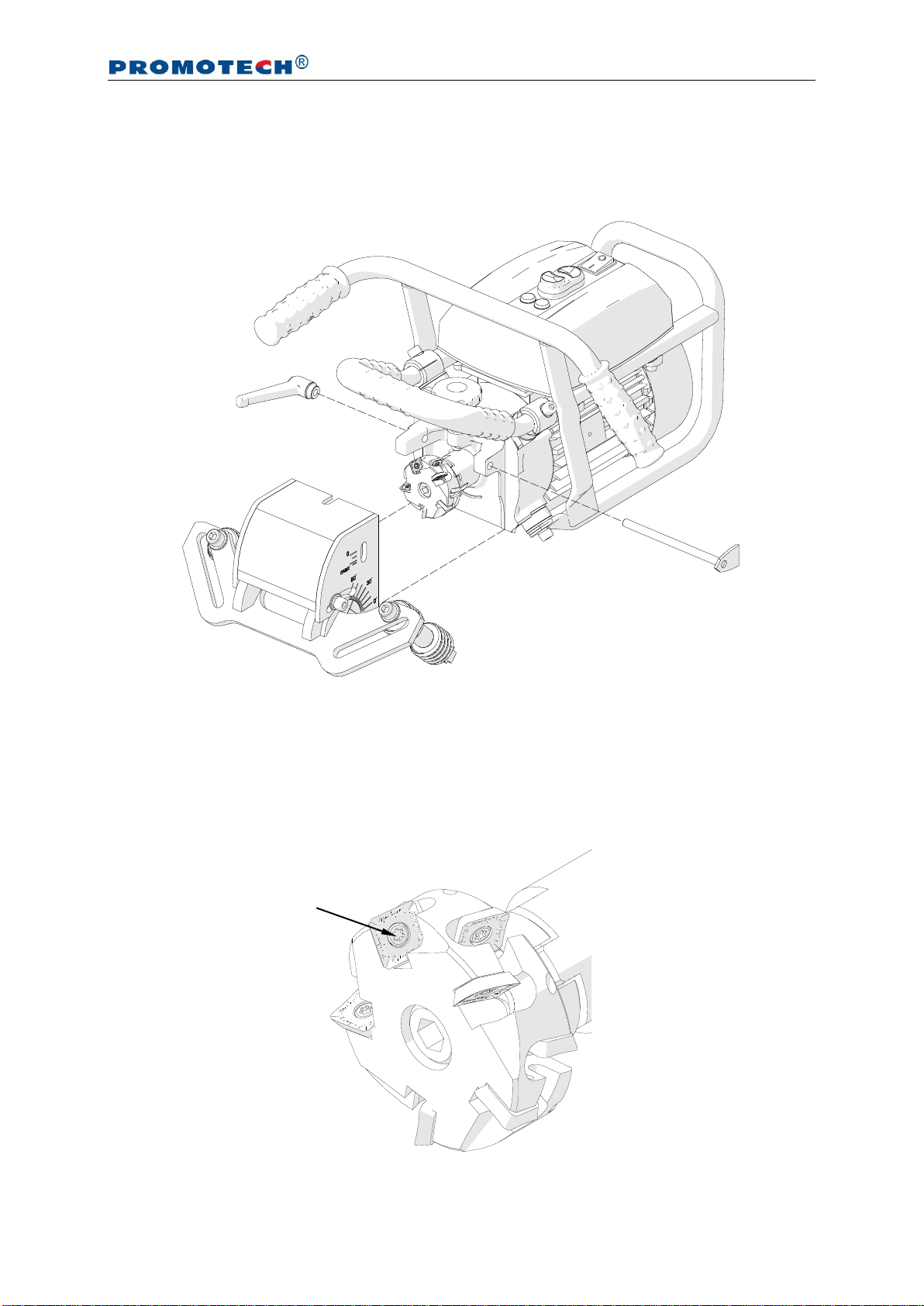
3.5. Replacing the cutting inserts
Unplug the power cord from the power outlet, unscrew the lever (1, Fig. 12), and
remove the indicator (2) and the milling head cover (3).
Fig. 12. Removing the milling head cover
Use the supplied T15P screwdriver to unscrew the mounting screw (Fig. 13), then
remove the insert, and clean the socket. Next, rotate the insert by 90°and mount
again or replace to a new one if all four edges are worn. To replace an insert from the
internal ring, first remove the insert from the external ring.
Fig. 13. Replacing the cutting inserts
2
1
3
Mounting screw
BM-21S
This document is protected by copyrights.
Copying, using, or distributing without permission of PROMOTECH is prohibited.
17
When making bevels of low width, the cutting inserts wear only on one, internal
corner. Then, the good action is to change the inserts between the rings of the milling
head (Fig. 14), which will extend the life of the inserts.
Fig. 14. Changing the cutting inserts between rings
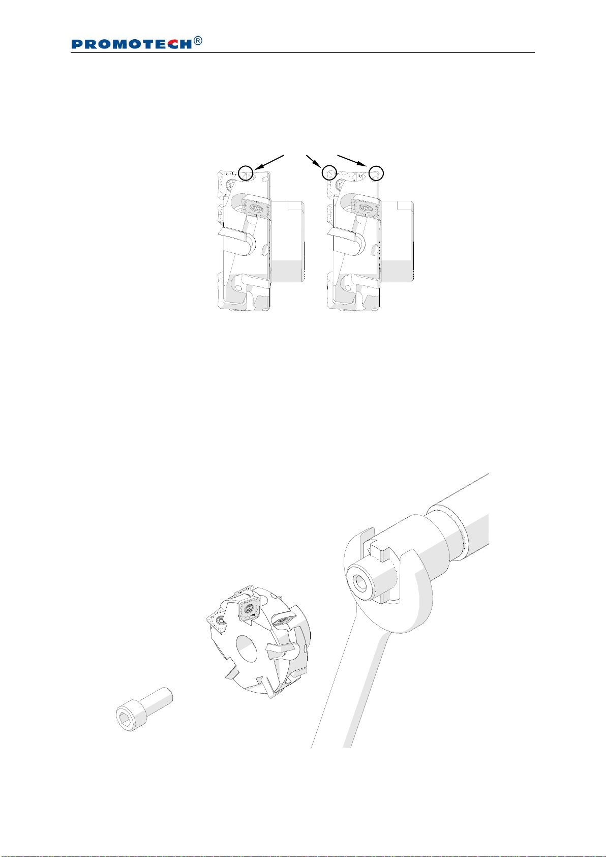
3.6. Replacing the milling head
Remove the milling head cover as shown in Fig. 12. Next, lock the rotation of the
spindle with the 32 mm flat wrench (Fig. 15), use the 8 mm hex wrench to unscrew
the screw, and remove the milling head. The 32 mm flat wrench is not included in
standard equipment.
Fig. 15. Replacing the milling head
Worn corners

BM-21S
This document is protected by copyrights.
Copying, using, or distributing without permission of PROMOTECH is prohibited.
18
4. WIRING DIAGRAM

BM-21S
This document is protected by copyrights.
Copying, using, or distributing without permission of PROMOTECH is prohibited.
19
5. SPARE AND WEARING PARTS
Name
Number
Milling head (including mounting screws,
screwdriver, and grease; 10 inserts required)
GLW-0461-03-00-00-0
Cutting insert (sold 10 per box)
PLY-000282
Mounting screw for inserts
SRB-000311
T15P torx screwdriver for mounting screws
WKT-000005
Grease for screws (5 g, 0.17 oz)
SMR-000005
Oil for stainless steel (0.5 kg, 1.1 lbs)
OLJ-000004

BM-21S
This document is protected by copyrights.
Copying, using, or distributing without permission of PROMOTECH is prohibited.
20
6. DECLARATION OF CONFORMITY
EC Declaration of Conformity
We
PROMOTECH sp. z o.o.
ul. Elewatorska 23/1
15-620 Bialystok
Poland
declare with full responsibility that product:
BM-21S Bevelling Machine
which the declaration applies to is in accordance with the following standard:
EN 50144-1
and satisfies safety regulations of the guidelines: 2006/95/EC and 2006/42/EC.
Bialystok, 8 November 2011 ___________________________
Marek Siergiej
Chairman
Table of contents
Other Promotech Power Tools manuals


