Promotech PRO 10 PB User manual


Contents
1. GENERAL INFORMATION............................................................................................... 3
1.1. Application................................................................................................................. 3
1.2. Technical data............................................................................................................ 3
1.3. Design ....................................................................................................................... 5
1.4. Equipment included ................................................................................................... 6
2. SAFETY PRECAUTIONS.................................................................................................. 7
3. STARTUP AND OPERATION........................................................................................... 9
3.1. Installing the jaw blocks, adapters, tool holders, and tool bits..................................... 9
3.2. Installing (removing) the mandrel and adjusting the clearance..................................10
3.3. Installing the motor....................................................................................................11
3.4. Clamping the machine into the pipe..........................................................................12
3.5. Preparing the air (for machine with air motor) ...........................................................13
3.6. Operating..................................................................................................................13
4. ACCESSORIES...............................................................................................................15
4.1. Small expanding mandrel set....................................................................................15
4.2. Extension set............................................................................................................16
4.3. Large expanding mandrel .........................................................................................17
4.4. Flange facing attachment..........................................................................................18
4.4.1. General information........................................................................................18
4.4.2. Equipment included........................................................................................18
4.4.3. Installing.........................................................................................................19
4.4.4. Operating .......................................................................................................21
4.4.5. Adjusting the slider clearance.........................................................................22
4.5. Oval attachment........................................................................................................23
4.5.1. General information........................................................................................23
4.5.2. Equipment included........................................................................................23
4.5.3. Installing.........................................................................................................24
4.5.4. Operating .......................................................................................................25
4.5.5. Adjusting the slider clearance.........................................................................26
5. ADDITIONAL EQUIPMENT AND WEARING PARTS.......................................................27
6. DECLARATIONS OF CONFORMITY...............................................................................28
7. QUALITY CERTIFICATE..................................................................................................30
8. WARRANTY CARD..........................................................................................................31

PRO 10 PB (PBE)
This document is protected by copyrights.
Copying, using, or distributing without permission of PROMOTECH is prohibited.
3
1. GENERAL INFORMATION
1.1. Application
The PRO 10 PB (PBE) is a pipe bevelling machine designed to mill edges of pipes
made of carbon and stainless steel, aluminum alloys, and copper-nickels. Depending
onthetoolbit used,the machine can perform external and internal bevelling,J-bevelling,
internal calibration, and facing pipes with internal diameters of 84–269 mm (3.31–
10.59’’). Up to three tool bits can be installed at the same time.
Using an optional small expanding mandrel will allow milling pipes with internal
diameters from 38 mm to 86 mm (1.50–3.39’’), and using an extension set will allow
milling pipes with diameters from 192 mm to 349 mm (7.56–13.74’’). Attachments will
allow facing pipe flanges with diameters from 90 to 508 mm (3.54–20.00’’) and milling
oval pipes from 126 mm to 296 mm (4.96–11.65’’).
1.2. Technical data
PRO 10 PB
PRO 10 PBE
Pressure
0.6 MPa (87 psi)
–
Voltage
–
1~ 110–120 V, 50–60 Hz
1~ 220–240 V, 50–60 Hz
Connection
CEJN 410 DN 10.4 GZ 3/8’’
BSPT coupling
electrical plug
Air consumption
1750 Nl/min (62 CFM)
–
Power
1800 W
1800 W
Pipe internal diameter
84–269 mm (3.31–10.59’’)
84–269 mm (3.31–10.59’’)
Maximum pipe wall thickness
15 mm (0.59’’)
15 mm (0.59’’)
Rotational speed without load
17 rpm
–
Nominal rotational speed
9 rpm
12–29 rpm (gear I)
41–96 rpm (gear II)
Protection class
–
II
Required ambient temperature
0–40°C (34–104°F)
0–40°C (34–104°F)
Noise level
above 70 dB
below 70 dB
Weight (with motor)
33 kg (73 lbs)
35.9 kg (79 lbs)

PRO 10 PB (PBE)
This document is protected by copyrights.
Copying, using, or distributing without permission of PROMOTECH is prohibited.
4
547 mm (21.5’’)
306 mm (12.0’’)
780 mm (30.7’’)
648 mm (25.5’’)
306 mm (12.0’’)
724 mm (28.5’’)
PBE-10
PB-10

PRO 10 PB (PBE)
This document is protected by copyrights.
Copying, using, or distributing without permission of PROMOTECH is prohibited.
5
1.3. Design
Fig. 1.View of the PRO 10 PB and of the PRO 10 PBE electric motor
Spoke handle
Clearance adjusting unit
Expanding mandrel
Spindle disk
Air motor
ON/OFF lever
Air connection
Draw nut
Tool bit holder
Gear switch
Rotation direction switch
(must be set to R)
ON switch
ON switch lock
Speed adjustment dial
Torque adjusting dial
Electric motor
Feed indicator

PRO 10 PB (PBE)
This document is protected by copyrights.
Copying, using, or distributing without permission of PROMOTECH is prohibited.
6
1.4. Equipment included
The PRO 10 PB (PBE) is supplied in a metal box with complete standard equipment.
The included equipment consists of the following elements.
PRO 10 PB
PRO 10 PBE
Bevelling machine (without tool bits)
1 unit
1 unit
Standard expanding mandrel
1 unit
1 unit
Metal box
1 unit
1 unit
Jaw blocks (number 1, 2, 3, 4, 5, 6) and adapter
3 sets
3 sets
Coolant container
1 unit
1 unit
Tool container
1 unit
1 unit
6 mm hex wrench
1 unit
1 unit
5 mm hex wrench
1 unit
1 unit
4 mm hex wrench
1 unit
1 unit
24 mm socket wrench with handle
1 unit
1 unit
Operator’s Manual
1 unit
1 unit

PRO 10 PB (PBE)
This document is protected by copyrights.
Copying, using, or distributing without permission of PROMOTECH is prohibited.
7
2. SAFETY PRECAUTIONS
1. Before beginning, read this Operator’s Manual and complete proper occupational
safety and health training.
2. The machine must be used only in applications specified in this Operator’s Manual.
3. The machine must be complete and all parts must be genuine and fully operational.
4. The specifications of the air (power) source must conform to those specified on the
ratingplate.
5. Supply the machine with air motor only with clean and lubricated air. The air source
must be equipped with a filter, regulator, and lubricator.
6. Never pull the hose (cord) as this may cause its damage and result in serious injury.
7. Untrained bystanders must not be present near the machine.
8. Before beginningcheck the condition of the machine and air(power)source, including
the supply hose (cord), coupling (plug), control components, and milling tools.
9. Avoid unintentional starts. Do not lay the machine down in such a manner that will
start the motor and never carry the machine with air motor using the ON/OFF lever.
10. Keep the machine dry. Exposure to rain, snow, or frost is prohibited.
11. Keep the work area well lit, clean, and free of obstacles.
12. Never use machine near flammable liquids or gases, or in explosive environments.
13. Secure the pipe to prevent it from dropping or rolling.
14. Use only tools specified in this Operator’s Manual.
15. Never use tools that are dull or damaged.
16. Install tools securely. Remove adjusting keys and wrenches from the work area
before connecting the machine to the air (power) source.
17. Before every use, inspect the machine to ensure it is not damaged. Check whether
any part is cracked or improperly fitted. Make sure to maintain proper conditions
that may affect the operation of the machine.
18. Always use eye and hearing protection, protective footwear, and protective clothing
during operation. Do not wear loose clothing.
19. Operate the machine with electric motor only with the rotation direction switch set
to position ‘R’. Using left rotation (rotation direction switch set to ‘L’) may damage
the machine.
20. Do not touch moving parts or metal chips formed during milling. Prevent objects
from being caught in moving parts.

PRO 10 PB (PBE)
This document is protected by copyrights.
Copying, using, or distributing without permission of PROMOTECH is prohibited.
8
21. After every use, remove metal chips and excess coolant from the machine. Never
remove chips with bare hands. Clean the machine with a cotton cloth without
using any agents.
22. Cover steel parts with a thin grease layer to protect them against rust when not in
use for any extended period.
23. Maintain the machine and install/remove parts and tools only when the machine
is unplugged from the air (power) source.
24. Repair only in a service center appointed by the seller.
25. If the machine falls from any height, is wet, or has any other damage that could
affect the technical state of the machine, stop the operation and immediately
send the machine to the service center for inspection and repair.
26. Never leave the machine unattended during operation.
27. Remove from the worksite and store in a secure and dry location when not in
use, previously removing the tools from holders.
PRO 10 PB (PBE)
This document is protected by copyrights.
Copying, using, or distributing without permission of PROMOTECH is prohibited.
9
3. STARTUP AND OPERATION
3.1. Installing the jaw blocks, adapters, tool holders, and tool bits
Use the following table to select jaw blocks and adapters suitable to the diameter of
the pipe to be machined.
Pipe internal diameter
Jaw block
number
Adapter
[mm]
[inch]
84–100
3.31–3.94
–
–
99–115
3.90–4.53
1
–
115–131
4.53–5.16
2
–
130–146
5.12–5.75
3
–
146–162
5.75–6.38
4
–
161–177
6.34–6.97
5
–
176–192
6.93–7.56
6
–
192–208
7.56–8.19
2
+
207–223
8.15–8.78
3
+
223–239
8.78–9.41
4
+
238–254
9.37–10.00
5
+
253–269
9.96–10.59
6
+
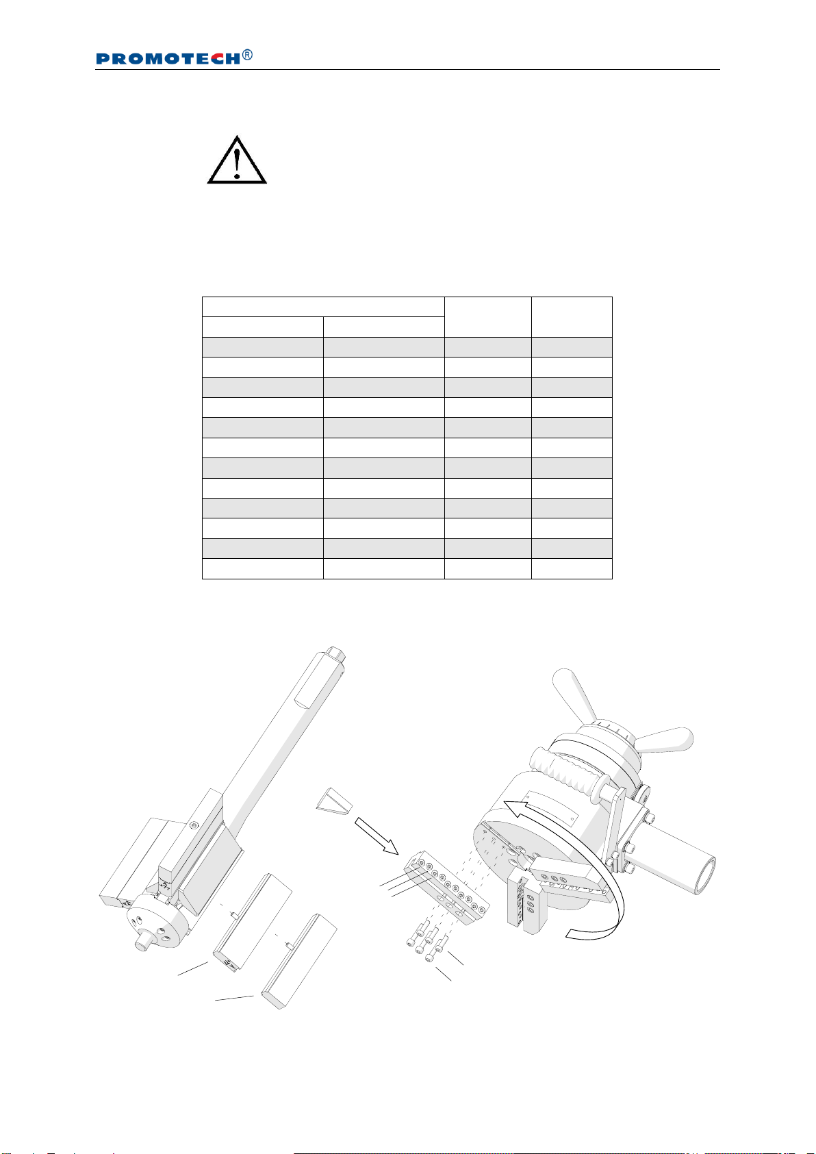
Use the 5 mm hex wrench to screw the adapters (1, Fig. 2) and the jaw blocks 2to
the expanding mandrel.
Fig. 2.Installing the jaw blocks, adapters, tool holders, and tool bits
Adhere to all safety precautions.
1
3
4
2
4
5
M6x30
M6x20
PRO 10 PB (PBE)
This document is protected by copyrights.
Copying, using, or distributing without permission of PROMOTECH is prohibited.
10
Use the same 5 mm hex wrench to install the tool holders to the spindle disk
using six screws (3). Then, select up to three tool bits suitable to planned use and
attach them to the holders according to the rotation direction 4. Next, tighten the
screws 5using the 4 mm hex wrench.
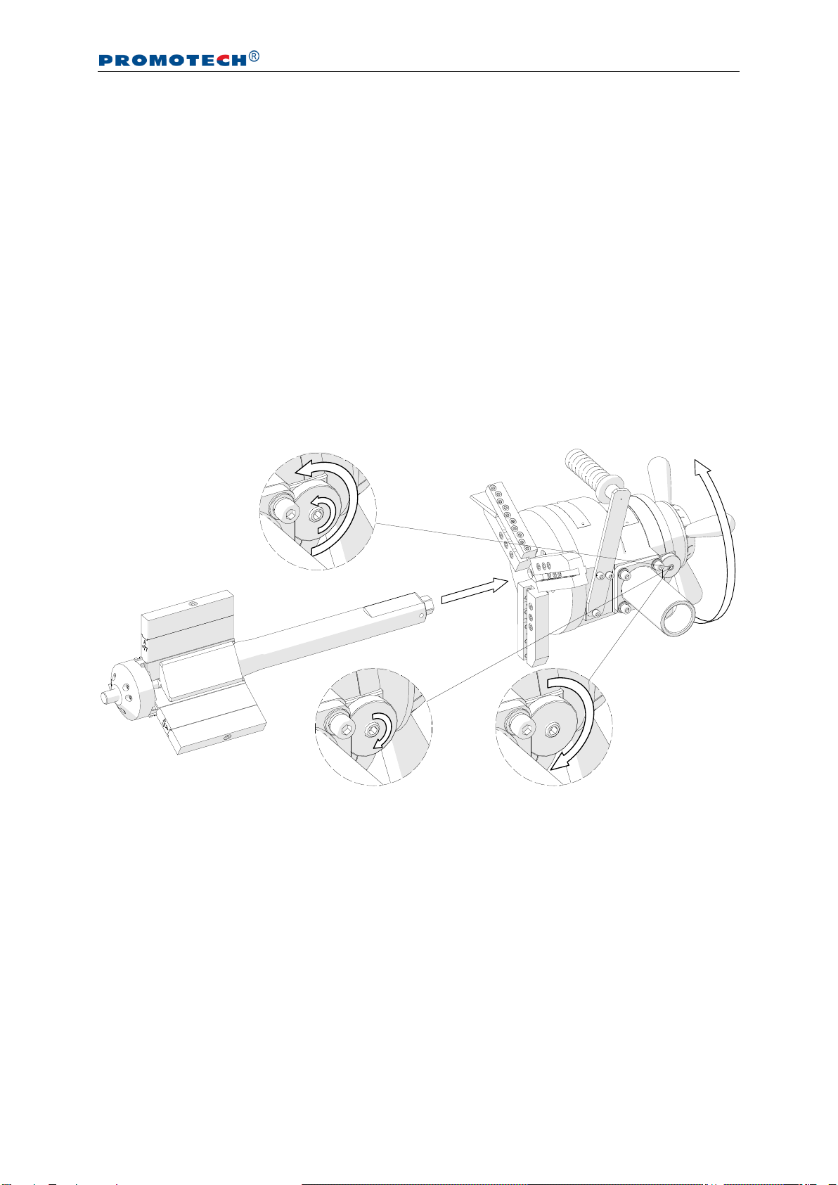
3.2. Installing (removing) the mandrel and adjusting the clearance
Loosen the nut and use the 5 mm hex wrench to loosen the set screw (1, Fig. 3), and
insert the mandrel into the machine (2). Make sure that tool bits installed are not in
contact with the mandrel. Next, rotate the spoke handles to the right (3) by at least 10
turns until the mandrel engages with the machine completely. Then, tighten the set
screw (4)and check whether the spoke handles can be rotated in both directions
easily. If the screw is too tight, readjust it. Finally, tighten the lock nut (5).
Fig. 3. Installing the mandrel into the machine
If the expanding mandrel becomes loose causing vibrations of the tool bits during
machining, perform the above actions without removing the mandrel from the machine.
To remove the mandrel, loosen the nut and use the 5 mm hex wrench to loosen the
set screw (1,Fig. 3) to at least one turn. Then, rotate the spoke handles to the left to
disengage the mandrel from the machine.
1
2
4
5
3
3

PRO 10 PB (PBE)
This document is protected by copyrights.
Copying, using, or distributing without permission of PROMOTECH is prohibited.
11
3.3. Installing the motor
Insert the air motor into the machine (1, Fig. 4a) in such a way to place the arbor in
the socket 2, and tighten the motor by rotating it to the left (3).
Fig. 4. Installing the air motor (a) and the electric motor (b)
To install the electric motor, insert the MT3 arbor into the motor (4, Fig. 4b), and hit
the arbor to position it tightly using a mallet. Put the clamping ring (5) onto the motor,
then install entirety into the machine (6)by placing the arbor in the socket 2, and tighten
the clamping ring using the 6 mm hex wrench (7). Finally, set the rotation direction
switch in position R as in Fig. 1.
3
4
6
2
1
5
7
b)
a)

PRO 10 PB (PBE)
This document is protected by copyrights.
Copying, using, or distributing without permission of PROMOTECH is prohibited.
12
3.4. Clamping the machine into the pipe
Insert the assembled machine into the pipe (1, Fig. 5) in such a way to place the tool
bit(s) at the distance of at least 3 mm (0.12’’) from the pipe end. Then, expand the
jaw blocks to the inside diameter of the pipe by rotating the draw nut 2to the right
using the 24 mm socket wrench. The jaw blocks must be installed beyond the end
preparation location 3.
Fig. 5.Clamping the machine into the pipe
3
3
1
2
PRO 10 PB (PBE)
This document is protected by copyrights.
Copying, using, or distributing without permission of PROMOTECH is prohibited.
13
3.5. Preparing the air (for machine with air motor)
Connect the machine to a correctly prepared air supply of sufficient purity using
a hose with the internal diameter of at least 12 mm (0.5’’). The air installation must be
equipped with an air preparation unit: filter, regulator, and lubricator (FRL).
Maintain the FRL unit as required to keep the water trap drained, filter cleaned,
and the lubricator oil reservoir filled so that there is a drop of oil every 2–5 seconds.
Use only oil whose ignition temperature exceeds 260°C (500°F). If the machine is to
be left idle for at least 24 hours, increase the delivery of oil and run the motor for 2–3
seconds, which will prevent rusting and degrading of the rotor vanes.
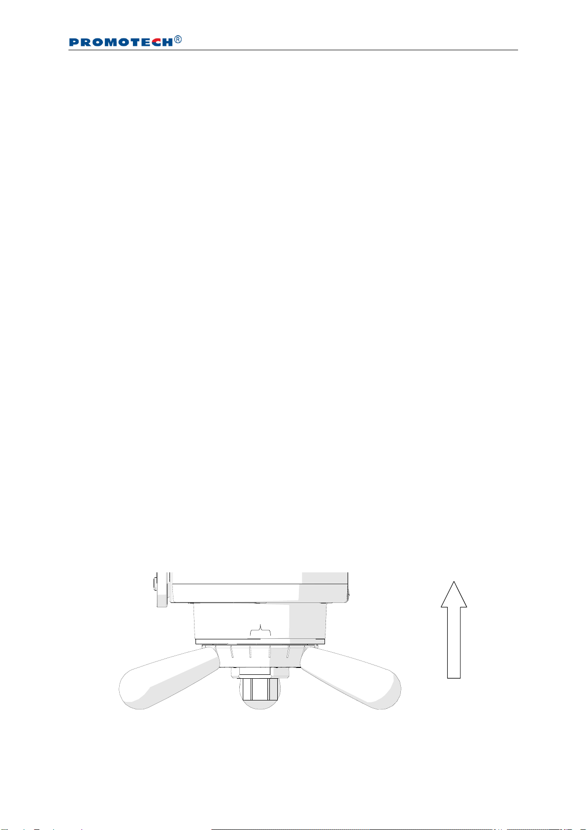
3.6. Operating
Once the machine is connected to a proper supply, set the maximum torque using
the torque adjusting dial and select gear Iusing the gear switch (only for machine with
electric motor). To start the operation, press the ON/OFF lever (air machine) or hold
the ON switch (electric machine). To lock the switch in position ON, press the ON switch
lock first.
Spread the coolant on the working edge. Then, bring the tool bit(s) close to the pipe
by rotating the spoke handles to the right. If the pipe face is not perpendicular to the
pipe axis, the tool bit will machine only a small segment of the pipe during initial
rotations. Thus, the feed rate should be chosen low until the tool bit is contacting the
pipe continually during at least one rotation. The axial feed is 0.11 mm (0.004’’) per
graduation (Fig. 6) or 2 mm (0.08’’) per one complete turn of the spoke handles. The
machine with electric motor allows toggling the speed between gear I and II after
stopping the rotation, and adjusting the rotational speed.
Fig. 6.View of the feed indicator
Feed direction
Feed = 0.11 mm (0.004’’)

PRO 10 PB (PBE)
This document is protected by copyrights.
Copying, using, or distributing without permission of PROMOTECH is prohibited.
14
Continue machining by rotating the spoke handles to the right. Use adequate feed
rate to establish a continuous chip cut. If the feed rate is too low, only light stringer
chips will be removed, while too high feed will make machining difficult and the chip
will start to have a rough or torn appearance. Never allow the tool bit to burnish the
surface. Change the feed rate to minimize chatter problems if they occur. Stainless
steel, which work hardens, must be worked with a high enough feed, 0.08–0.15 mm
(0.003–0.006’’) per rotation, to stay under the work hardened surface.
Once the pipe end is machined completely, discontinue rotating the spoke handles
and allow the spindle to rotate several more turns to improve the finish of the surface.
Then, turn off the motor by releasing the ON/OFF lever, or the ON switch in the
machine with electric motor, and wait until the rotation stops. Separate the tool bit(s)
from the pipe end to at least 3 mm (0.12’’) by rotating the spoke handles to the left.
Finally, loosen the draw nut using the 24 mm socket wrench to release the clamping,
and remove the machine from the pipe. Use petroleum ether to clean the pipe from
excess coolant. Clean the machine with a cotton cloth without using any agents.

PRO 10 PB (PBE)
This document is protected by copyrights.
Copying, using, or distributing without permission of PROMOTECH is prohibited.
15
4. ACCESSORIES
4.1. Small expanding mandrel set
Allows machining pipes with internal diameters from 38 to 86 mm (1.50–3.39’’).
Included equipment consists of the following elements.
Small expanding mandrel
1 unit
Jaw blocks (number I, II, III, IV)
3 sets
3 mm hex wrench
1 unit
Install the mandrel after previously removing the existing expanding mandrel.
To do this, loosen the nut and use the 5 mm hex wrench to loosen the set screw (1,
Fig. 3) to at least one turn. Then, rotate the spoke handles to the left to disengage the
mandrel from the machine.
Then, use the following table to select jaw blocks of the small expanding mandrel
set suitable to the inside diameter of the pipe to be machined, use the 3 mm hex
wrench to tighten them to the small expanding mandrel as shown in Fig. 2, and install
the mandrel into the machine (2, 3, 4, 5, Fig. 3).
Pipe internal diameter
with small expanding mandrel
Jaw block
number
[mm]
[inch]
38–47.5
1.50–1.87
–
47.5–57.5
1.87–2.26
I
57–67
2.24–2.64
II
66.5–76.5
2.62–3.01
III
76–86
2.99–3.39
IV
Part number:
ZSP-0200-05-00-00-2

PRO 10 PB (PBE)
This document is protected by copyrights.
Copying, using, or distributing without permission of PROMOTECH is prohibited.
16
4.2. Extension set
Allows machining pipes with internal diameters from 192 to 349 mm (7.56–13.74’’) in
combination with the standard expanding mandrel. Clamping inside a pipe with
diameter of 349 mm will enable machining up to 8 mm (0.31’’) of pipe wall.
Included equipment consists of the following elements.
Tool holder of extension set
3 units
Jaw blocks (number 7, 8, 9, 10, 11)
3 sets
Metal box
1 unit
5 mm hex wrench
1 unit
4 mm hex wrench
1 unit
Install the set after previously removing the existing tool holders. To do this, use
the 5 mm hex wrench to unscrew the screws (3, Fig. 2) and use them to install the
tool holders of the extension set.
Use the following table to select jaw blocks of the extension set suitable to the
inside diameter of the pipe to be machined, and use the same 5 mm hex wrench to
tighten them to the standard expanding mandrel as shown in Fig. 2. Then, install tool
bits in holders by tightening the screws (5, Fig. 2) using the 4 mm hex wrench.
Pipe internal diameter
with standard expanding
mandrel and jaw blocks of
extension set
Jaw block
number
Adapter
[mm]
[inch]
192–208
7.56–8.19
7
–
208–224
8.19–8.82
8
–
224–240
8.82–9.45
9
–
240–256
9.45–10.08
10
–
256–272
10.08–10.71
11
–
269–285
10.59–11.22
7
+
285–301
11.22–11.85
8
+
301–317
11.85–12.48
9
+
317–333
12.48–13.11
10
+
333–349
13.11–13.74
11
+
Part number:
ZST-0200-13-00-00-2

PRO 10 PB (PBE)
This document is protected by copyrights.
Copying, using, or distributing without permission of PROMOTECH is prohibited.
17
4.3. Large expanding mandrel
Allows machining pipes with internal diameters from 126 to 296 mm (4.96–11.65’’)
when used with standard jaw blocks. Additionally, when used with jaw blocks of the
extension set, the large expanding mandrel enables the machine to be installed inside
pipes with diameters from 219 to 376 mm (8.62–14.80’’) for flange facing.
Install the mandrel after previously removing the existing expanding mandrel.
To do this, loosen the nut and use the 5 mm hex wrench to loosen the set screw (1,
Fig. 3) to at least one turn. Then, rotate the spoke handles to the left to disengage the
mandrel from the machine.
Use the following table to select either standard jaw blocks suitable to the inside
diameter of the pipe to be machined or jaws blocks of the extension set for flange
facing. Then, use the 5mm hex wrench to tighten them to the large expanding mandrel
as shown in Fig. 2, and install the mandrel into the machine (2, 3, 4, 5, Fig. 3).
Pipe internal diameter
with large expanding
mandrel and standard
jaw blocks
Jaw
block
number
Adapter
Pipe internal diameter
with large expanding
mandrel and jaw blocks of
extension set
Jaw
block
number
Adapter
[mm]
[inch]
[mm]
[inch]
126–142
4.96–5.59
1
–
219–235
8.62–9.25
7
–
142–158
5.59–6.22
2
–
235–251
9.25–9.88
8
–
157–173
6.18–6.81
3
–
251–267
9.88–10.51
9
–
173–189
6.81–7.44
4
–
267–283
10.51–11.14
10
–
188–204
7.40–8.03
5
–
283–299
11.14–11.77
11
–
203–219
7.99–8.62
6
–
296–312
11.65–12.28
7
+
219–235
8.62–9.25
2
+
312–328
12.28–12.91
8
+
234–250
9.21–9.84
3
+
328–344
12.91–13.54
9
+
250–266
9.84–10.47
4
+
344–360
13.54–14.17
10
+
265–281
10.43–11.06
5
+
360–376
14.17–14.80
11
+
280–296
11.02–11.65
6
+
Part number:
TRZ-0200-50-00-00-0
PRO 10 PB (PBE)
This document is protected by copyrights.
Copying, using, or distributing without permission of PROMOTECH is prohibited.
18
4.4. Flange facing attachment
4.4.1. General information
Allows facing flanges with diameters from 90 to 508 mm (3.54–20’’) with the machine
clamped inside a pipe with internal diameter either of 84–269 mm (3.31–10.59’’)
using the standard expanding mandrel or of 219–376 mm (8.62–14.8’’) using the
large expanding mandrel.
Flange diameter
90–508 mm (3.54–20’’)
Automatic feed range
180.5 mm (7.11’’)
Diameter of rotating parts
569.4 mm (22.42’’)
Feed per rotation
0.33 mm (0.013’’, with one tripper block engaged)
0.66 mm (0.026’’, with two tripper blocks engaged)
4.4.2. Equipment included
Equipment of the flange facing attachment consists of the following elements.
Milling unit for flanges
1 unit
Holder with two tripper blocks
1 unit
Cutting insert
8 units
Fixing screw for cutting insert
2 units
Internal insert holder
1 unit
External insert holder
1 unit
Metal box
1 unit
M6x35 screw
3 units
M6x30 screw
3 units
M6x14 screw
3 units
5 mm hex wrench
1 unit
4 mm hex wrench
1 unit
3 mm hex wrench
1 unit
13 mm combination wrench
1 unit
T15 screwdriver
1 unit
Tool container
1 unit
Part number:
PRK-0447-00-00-00-2

PRO 10 PB (PBE)
This document is protected by copyrights.
Copying, using, or distributing without permission of PROMOTECH is prohibited.
19
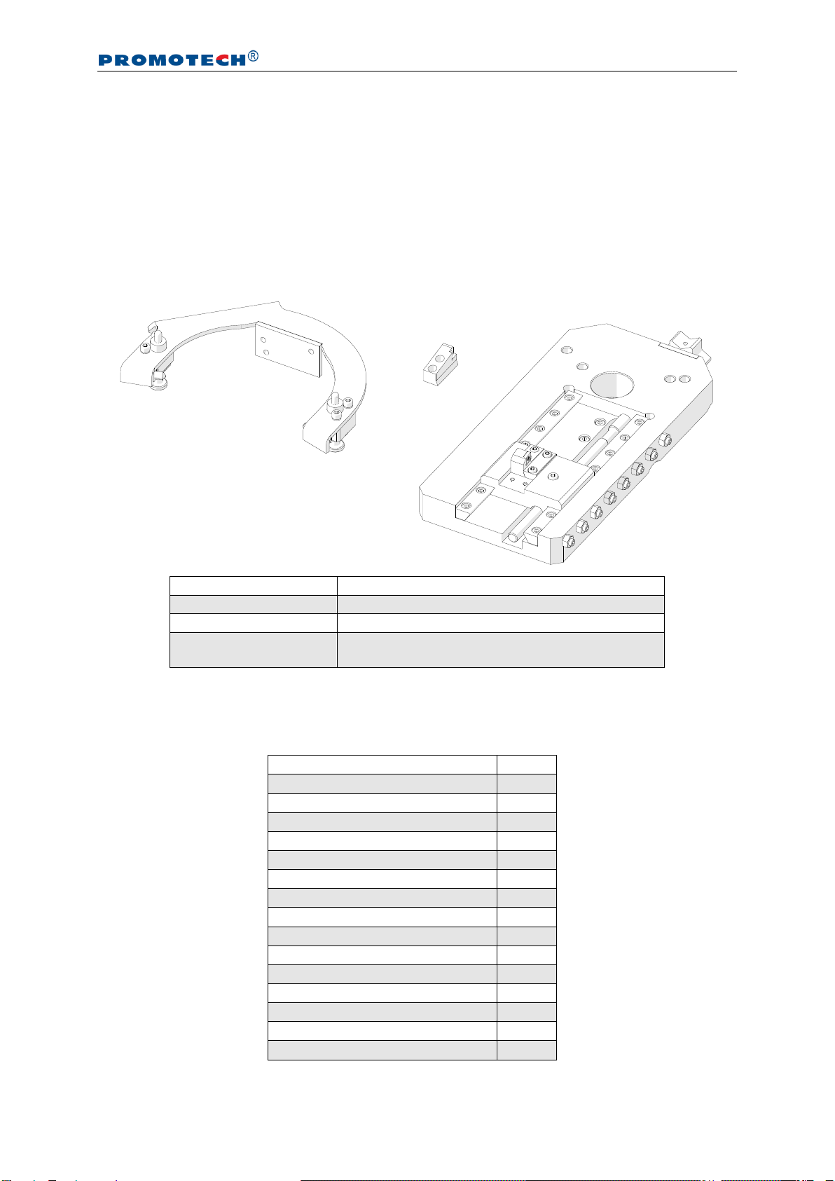
4.4.3. Installing
Remove the existing expanding mandrel. To do this, loosen the nut and use the 5 mm
hex wrench to loosen the set screw (1, Fig. 3) to at least one turn. Then, rotate the
spoke handles to the left to disengage the mandrel from the machine.
Use the same 5 mm hex wrench to unscrew the screws (3, Fig. 2) and remove
the existing tool holders.
Next, remove the machine handle by unscrewing three screws with washers (1,
Fig. 7), and use them to install the holder with two tripper blocks (2). Then, use the
4 mm hex wrench to tighten the set screws 3at both sides of the holder, and install
the milling unit to the spindle disk (4) with six screws using the 5 mm hex wrench.
Fig. 7.Installing the flange facing attachment
Depending on the diameter of the flange to be machined, select either the
internal (Ø90–451, 3.54–17.76’’) or external insert holder (Ø147–508, 5.79–20.00’’),
onto which install a cutting insert using the supplied screwdriver (1, Fig. 8). Then, use
the 4 mm hex wrench to tighten the clamp 2, and slide the insert holder under the
clamp (3) and tighten with the screws 4.
1
2
3
M6x35
M6x30
4

PRO 10 PB (PBE)
This document is protected by copyrights.
Copying, using, or distributing without permission of PROMOTECH is prohibited.
20
Fig. 8.Installing the tool
Next, use the following table to either select standard jaw blocks suitable to the
inside diameter of the flange to be machined and screw them to the standard
expanding mandrel or select jaw blocks of the extension set and attach them to the
large expanding mandrel (Fig. 2).
Pipe internal diameter
with standard expanding
mandrel and standard
jaw blocks
Jaw
block
number
Adapter
Pipe internal diameter
with large expanding
mandrel and jaw blocks of
extension set
Jaw
block
number
Adapter
[mm]
[inch]
[mm]
[inch]
84–100
3.31–3.94
–
–
219–235
8.62–9.25
7
–
99–115
3.90–4.53
1
–
235–251
9.25–9.88
8
–
115–131
4.53–5.16
2
–
251–267
9.88–10.51
9
–
130–146
5.12–5.75
3
–
267–283
10.51–11.14
10
–
146–162
5.75–6.38
4
–
283–299
11.14–11.77
11
–
161–177
6.34–6.97
5
–
296–312
11.65–12.28
7
+
176–192
6.93–7.56
6
–
312–328
12.28–12.91
8
+
192–208
7.56–8.19
2
+
328–344
12.91–13.54
9
+
207–223
8.15–8.78
3
+
344–360
13.54–14.17
10
+
223–239
8.78–9.41
4
+
360–376
14.17–14.80
11
+
238–254
9.37–10.00
5
+
253–269
9.96–10.59
6
+
Finally, install the mandrel into the machine (2, 3, 4, 5, Fig. 3) and clamp the
machine into the pipe as shown in Fig. 5.
1
2
3
4
External
insert holder
Internal
insert holder
Rotation direction
This manual suits for next models
1
Table of contents
Other Promotech Power Tools manuals


