Palmgren 84261A User manual

operating manual & parts list 84261A
61/8″
BENCH TOP
JOINTER/PLANER
Read carefully and follow all safety rules and operating instructions before
first use of this product.
25164.09-0207

DESCRIPTION
Palmgren 61/8″jointer/planer is used to surface the faces and
edges of boards, produce a flat surface on warped boards and
shape bevels, chamfers and tapers.The jointer/planer features cast
iron infeed and outfeed tables, cast iron body with smooth work
surfaces and lead screws for precise table height adjustment.
Balanced guide fence tilts 45° (inward) and 45° (outward). Built-in
blower for chip removal.Tool comes with locking rocker switch
with removable key and push blocks. Jointer/planer easily handles
rough-cut lumber, planes hard and soft woods up to 61/8″wide
using a two blade cutterhead, and takes cuts up to 1/8″.
UNPACKING
Refer to Figure 1.
Check for shipping damage. If damage has occurred, a claim must
be filed with carrier. Check for completeness. Immediately report
missing parts to dealer.
The jointer/planer is shipped complete in one carton. Additional
parts which need to be fastened to jointer/planer should be locat-
ed and accounted for before assembling.
A Jointer Bed Assembly
BFence
C Fence Support
D Fence Bracket Assembly
E Locking Plate Assembly
F Fence Sliding Handle with Spacer
G Push Blocks (2)
H Fence Tilting Handle with Spacer
I Dust Chute
J Half Bag Dust Collection Set
Hardware bag includes:
•8-1.25 x 20mm Socket Head Bolts (6)
•8mm Lock Washer (6)
•4 and 6mm Hex Wrench
•6-1.0 x 25mm Pan Head Screw
SPECIFICATIONS
Table Size . . . . . . . . . . . . . . . . . . . . . . . . . . . . . . . . . . . . . . . . . . . . . 285/8x 61/4″
Fence Size . . . . . . . . . . . . . . . . . . . . . . . . . . . . . . . . . . . . . . . . . . . . . 225/8x 33/4″
Blade Width. . . . . . . . . . . . . . . . . . . . . . . . . . . . . . . . . . . . . . . . . . . . . . . . . . 61/8″
Maximum Cut . . . . . . . . . . . . . . . . . . . . . . . . . . . . . . . . . . . . . . . . . . . 1/8″Deep
Cuts per Minute. . . . . . . . . . . . . . . . . . . . . . . . . . . . . . . . . . . . . . . . . . . . 20,000
Overall Size . . . . . . . . . . . . . . . . . . . . . . . . . . . . . . . . . . . . . . . . 285/8x 18 x 12″
Dust Collection Port . . . . . . . . . . . . . . . . . . . . . . . . . . . . . . . . 21/2″Diameter
Weight . . . . . . . . . . . . . . . . . . . . . . . . . . . . . . . . . . . . . . . . . . . . . . . . . . . . . 95 lbs
Motor . . . . . . . . . . . . . . . . . . . . . . . . . . . . . . . . . . . . . . . . . . . . . 1 HP, 12A, 120V
SAFETY RULES
WARNING: Some dust created by power sanding, sawing, grind-
ing, drilling and other construction activities contains chemicals
known to cause cancer, birth defects or other reproductive harm.
Some examples of these chemicals are:
•Lead from lead-based paints.
•Crystalline silica from bricks and cement and other masonry
products.
•Arsenic and chromium from chemically-treated lumber.
Your risk from these exposures vary, depending on how often you
do this type of work.To reduce your exposure to these chemicals:
work in a well ventilated area and work with approved safety
equipment. Always wear OSHA/NIOSH approved, properly fitting
face mask or respirator when using such tools.
WARNING: For your own safety, read all of the rules and precau-
tions before operating tool.
CAUTION: Always follow proper operating procedures as defined
in this manual even if you are familiar with use of this or similar
tools. Remember that being careless for even a fraction of a second
can result in severe personal injury.
BE PREPARED FOR JOB
•Wear proper apparel. Do not wear loose clothing, gloves, neck-
ties, rings, bracelets or other jewelry which may get caught in
moving parts of machine.
•Wear protective hair covering to contain long hair.
•Wear safety shoes with non-slip soles.
•Wear safety glasses complying with United States ANSI Z87.1.
Everyday glasses have only impact resistant lenses.They are
NOT safety glasses.
•Wear face mask or dust mask if operation is dusty.
•Be alert and think clearly. Never operate power tools when
tired, intoxicated or when taking medications that cause
drowsiness.
PREPARE WORK AREA FOR JOB
•Keep work area clean. Cluttered work areas invite accidents.
•Do not use power tools in dangerous environments.
•Do not use power tools in damp or wet locations. Do not
expose power tools to rain.
•Work area should be properly lighted.
•Proper electrical receptacle should be available for tool.Three-
prong plug should be plugged directly into properly grounded,
three-prong receptacle.
•Extension cords should have a grounding prong and the three
wires of the extension cord should be of the correct gauge.
•Keep visitors at a safe distance from work area.
•Keep children out of workplace. Make workshop childproof. Use
padlocks, master switches or remove switch keys to prevent
any unintentional use of power tools.
2
Palmgren Operating Manual & Parts List 84261A
A
B
J
E
G
H
I
F
C
D
Figure 1 – Unpacking

SAFETY RULES (CONTINUED)
TOOL SHOULD BE MAINTAINED
•Always unplug tool prior to inspection.
•Consult manual for specific maintaining and adjusting
procedures.
•Keep tool lubricated and clean for safest operation.
•Remove adjusting tools. Form habit of checking to see that
adjusting tools are removed before switching machine on.
•Keep all parts in working order. Check to determine that the
guard or other parts will operate properly and perform their
intended function.
•Check for damaged parts. Check for alignment of moving parts,
binding, breakage, mounting and any other condition that may
affect a tool’s operation.
•A guard or other part that is damaged should be properly
repaired or replaced. Do not perform makeshift repairs. (Use
parts list provided to order replacement parts.)
KNOW HOW TO USE TOOL
•Use right tool for job. Do not force tool or attachment to do a
job for which it was not designed.
•Disconnect tool when changing blades.
•Avoid accidental start-up. Make sure that the switch is in the
OFF position before plugging in.
•Do not force tool. It will work most efficiently at the rate for
which it was designed.
•Keep hands away from moving parts and cutting surfaces.
•Never leave tool running unattended. Turn the power off and
do not leave tool until it comes to a complete stop.
•Do not overreach. Keep proper footing and balance.
•Never stand on tool. Serious injury could occur if tool is tipped
or if blade is unintentionally contacted.
•Know your tool. Learn the tool’s operation, application and
specific limitations.
•Use recommended accessories (refer to page 15). Use of
improper accessories may cause risk of injury to persons.
•Handle workpiece correctly. Protect hands from possible injury.
•Turn machine off if it jams. Blade jams when it digs too deeply
into workpiece. (Motor force keeps it stuck in the work.)
•Always keep drive, cutterhead and blade guards in place and in
proper operating condition.
•Feed work into blade or cutter against direction of rotation.
CAUTION: Think safety! Safety is a combination of operator com-
mon sense and alertness at all times when tool is being used.
WARNING: Do not attempt to operate tool until it is completely
assembled according to the instructions.
ASSEMBLY
Refer to Figures 2, 3, 4 and 24.
ATTACH SUPPORT TO JOINTER
•Attach fence support to jointer with socket head bolts and lock
washers.
•Insert locking plate assembly into support. Position plate so
that pins are against bottom edge of support.
•Secure plate in position with fence sliding handle and spacer.
INSTALL FENCE AND FENCE BRACKET TO JOINTER
•Attach fence to fence bracket assembly with four socket head
bolts and lock washers.
•Slide fence and bracket over and onto dovetails of support and
locking plate.
•Continue to slide fence forward so that the fence is over the
jointer tables. At this position the edge of the blade guard will
rest against the fence, and the entire width of the cutterhead is
covered. Secure bracket in position with fence sliding handle.
•Insert fence tilting handle with spacer through right link and
thread into left link.
•Make sure limit plate (Figure 4) is resting in slot of block.
Position fence against shaft and lock fence in position with
fence tilting handle.
3
Palmgren Operating Manual & Parts List 84261A
Spacer
Fence Sliding Handle
Fence Support
Locking Plate
Assembly
Figure 2 – Attach Fence Support
Figure 3 – Attach Fence Assembly
Fence Tilting
Handle
Fence Bracket
Assembly
Support
Fence
Figure 4 – Limit Stops
Hex Nut
Limit Plate
Shaft
Shaft
Block
45° Inward Stop

4
ASSEMBLY (CONTINUED)
•Place a combination square against face of fence and table sur-
face. The fence and table must be at 90° to each other. If not,
loosen tilting handle, loosen hex nut and turn shaft with a
screw driver until fence is square. Secure in position by tighten-
ing hex nut.
•Use a bevel gauge or protractor to check 45° inward and out-
ward limit stops.The 45° inward stop is the hex head bolt locat-
ed beneath the shaft. The 45° outward stop is located at the top
of the fence. If adjustment is needed, loosen hex nut, turn hex
head bolt to proper position and secure in place with hex nut.
INSTALL DUST CHUTE
Refer to Figure 25, page 14.
•Insert pan head screw (Ref. No. 19) through tabs on dust chute
(Ref. No. 18). Slide dust chute onto end of chip exhaust (Ref. No.
17). Tighten pan head screw.
INSTALLING THE HALF BAG DUST COLLECTION SET
Refer to Figure 5.
The Palmgren Half Bag Dust Collection Set is designed to provide
dust collection for woodworking tools with a 21/2″diameter dust
exhaust port. The filter bag attachs to a 30-gallon trash can or a 30-
gallon x 1.3 mil plastic trash bag for easy, convenient sawdust dis-
posal (trash can and plastic trash bag not included).
To use dust collection set with a trash can:
•Place spring inside filter bag arm.
•Slide arm with spring over dust exhaust port.
•Place band of the bag over rim of trash can and secure bag by
tightening strap.
To use dust collection set with a trash bag:
•Place spring inside filter bag arm.
•Slide arm with spring over dust exhaust port.
•Assemble bag support. Slide connectors into channels of sup-
port segments.
•Slide plastic trash bag inside and over bag support. Let bag
overlap 3-4″.
•Place band of the filter bag over and into the channel of the
bag support.
•Secure in position by tightening strap.
INSTALLATION
Refer to Figures 6-9, pages 4 and 5.
The jointer/planer weighs approximately 95 lbs. when completely
assembled.The jointer/planer must be installed in a place with
ample lighting and correct power supply. To install jointer/planer:
•Make sure there is plenty of room for moving the workpiece
through the entire cut.There must be enough room that nei-
ther the operators nor the bystanders will have to stand in line
with the wood while using the tool.
•Jointer/planer can be installed on a workbench using bolts,
lock washers and hex nuts (not supplied).
•The jointer/planer must be bolted to a firm, level surface.
•Make sure the jointer/planer does not rock and the tables are
level.
POWER SOURCE
WARNING: Do not connect jointer/planer to the power source
until all assembly steps have been completed.
The motor is designed for operation on the voltage and frequency
specified. Normal loads will be handled safely on voltages not
more than 10% above or below specified voltage. Running the unit
on voltages which are not within range may cause overheating
and motor burn-out. Heavy loads require that voltage at motor ter-
minals be no less than the voltage specified on nameplate.
•Power supply to the motor is controlled by a rocker switch.
Removing the key from rocker switch will lock the unit and
prevent unauthorized use.
GROUNDING INSTRUCTIONS
WARNING: Improper connection of equipment grounding con-
ductor can result in the risk of electrical shock. Equipment should
be grounded while in use to protect operator from electrical
shock.
•Check with a qualified electrician if you do not understand
grounding instructions or if you are in doubt as to whether the
tool is properly grounded.
•This tool is equipped with an approved cord rated at 150V and
a 3-prong grounding type plug (see Figure 7) for your protec-
tion against shock hazards.
•Grounding plug should be plugged directly into a properly
installed and grounded 3-prong grounding-type receptacle, as
shown (see Figure 7).
Palmgren Operating Manual & Parts List 84261A
Figure 5 – Half Bag Dust Collection Set
Spring
Filter Bag
Band
Strap
Trash
Can
Trash
Bag
Dust Exhaust Port
Support
Segments
Connector
Bag
Support
Figure 7 – 3-Prong Receptacle
Grounding Prong
3-Prong Plug
Properly Grounded Outlet
Figure 6 – Jointer/Planer Foot Print
11″
5/16″
91/4″
171/4″
19″

Palmgren Operating Manual & Parts List 84261A
5
INSTALLATION (CONTINUED)
•Do not remove or alter grounding prong in any manner. In the
event of a malfunction or breakdown, grounding provides a
path of least resistance for electrical shock.
WARNING: Do not permit fingers to touch the terminals of plug
when installing or removing from outlet.
•Plug must be plugged into matching outlet that is properly
installed and grounded in accordance with all local codes and
ordinances. Do not modify plug provided. If it will not fit in out-
let, have proper outlet installed by a qualified electrician.
•Inspect tool cords periodically, and if damaged, have repaired
by an authorized service facility.
•Green (or green and yellow) conductor in cord is the grounding
wire. If repair or replacement of the electric cord or plug is nec-
essary, do not connect the green (or green and yellow) wire to
a live terminal.
•A 2-prong wall receptacle must be replaced with a properly
grounded 3-prong receptacle installed in accordance with
National Electric Code and local codes and ordinances.
WARNING: Any receptacle replacement should be performed by
a qualified electrician.
A temporary 3-prong to 2-prong grounding adapter (see Figure 8)
is available for connecting plugs to a two pole outlet if it is proper-
ly grounded.
•Do not use a 3-prong to 2-prong grounding adapter unless
permitted by local and national codes and ordinances.
(A 3-prong to 2-prong grounding adapter is not permitted
in Canada.)
Where a 3-prong to 2-prong grounding adapter is permitted,
the rigid green tab or terminal on the side of the adapter must
be securely connected to a permanent electrical ground such
as a properly grounded water pipe, a properly grounded outlet
box or a properly grounded wire system.
•Many cover plate screws, water pipes and outlet boxes are not
properly grounded. To ensure proper ground, grounding means
must be tested by a qualified electrician.
EXTENSION CORDS
•The use of any extension cord will cause some drop in voltage
and loss of power.
•Wires of the extension cord must be of sufficient size to carry
the current and maintain adequate voltage.
•Use the table to determine the minimum wire size (A.W.G.)
extension cord.
•Use only 3-wire extension cords having 3-prong grounding
type plugs and 3-pole receptacles which accept the tool plug.
•If the extension cord is worn, cut or damaged in any way,
replace it immediately.
EXTENSION CORD LENGTH
Wire Size A.W.G.
Up to 50 ft.. . . . . . . . . . . . . . . . . . . . . . . . . . . . . . . . . . . . . . . . . . . . . . . . . . . . . 16
50-100 ft. . . . . . . . . . . . . . . . . . . . . . . . . . . . . . . . . . . . . . . . . . . . . . . . . . . . . . . 14
NOTE: Using extension cords over 100 ft. long is not recommended.
MOTOR
Jointer/planer is supplied with a 1 HP motor.
The 120 Volt AC universal motor has the following specifications:
Horsepower . . . . . . . . . . . . . . . . . . . . . . . . . . . . . . . . . . . . . . . . . . . . . . . . . . . . 1
Voltage . . . . . . . . . . . . . . . . . . . . . . . . . . . . . . . . . . . . . . . . . . . . . . . . . . . . . . . 120
Amps . . . . . . . . . . . . . . . . . . . . . . . . . . . . . . . . . . . . . . . . . . . . . . . . . . . . . . . . . . 12
Hertz . . . . . . . . . . . . . . . . . . . . . . . . . . . . . . . . . . . . . . . . . . . . . . . . . . . . . . . . . . 60
Phase . . . . . . . . . . . . . . . . . . . . . . . . . . . . . . . . . . . . . . . . . . . . . . . . . . . . . . Single
Cutterhead RPM . . . . . . . . . . . . . . . . . . . . . . . . . . . . . . . . . . . . . . . . . . . 10,000
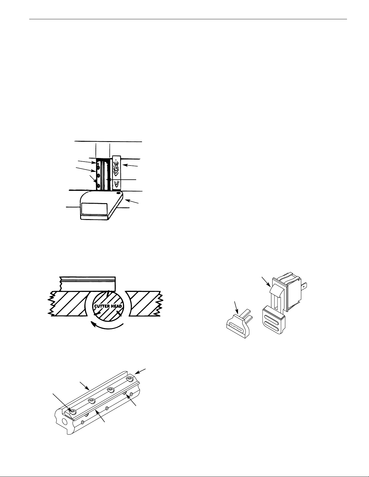
ELECTRICAL CONNECTIONS
WARNING: Make sure unit is turned off and disconnected from
power source before inspecting any wiring.
The unit is wired as illustrated in the wiring schematic (see Figure 9).
The motor is assembled with an approved three conductor cord to
be used on 120 volts as indicated. The power supply to the motor
is controlled by a double pole locking rocker switch.
•Remove the key to prevent unauthorized use.
The power lines are inserted directly onto the switch.The green
ground line must remain securely fastened to the frame to proper-
ly protect against electrical shock.
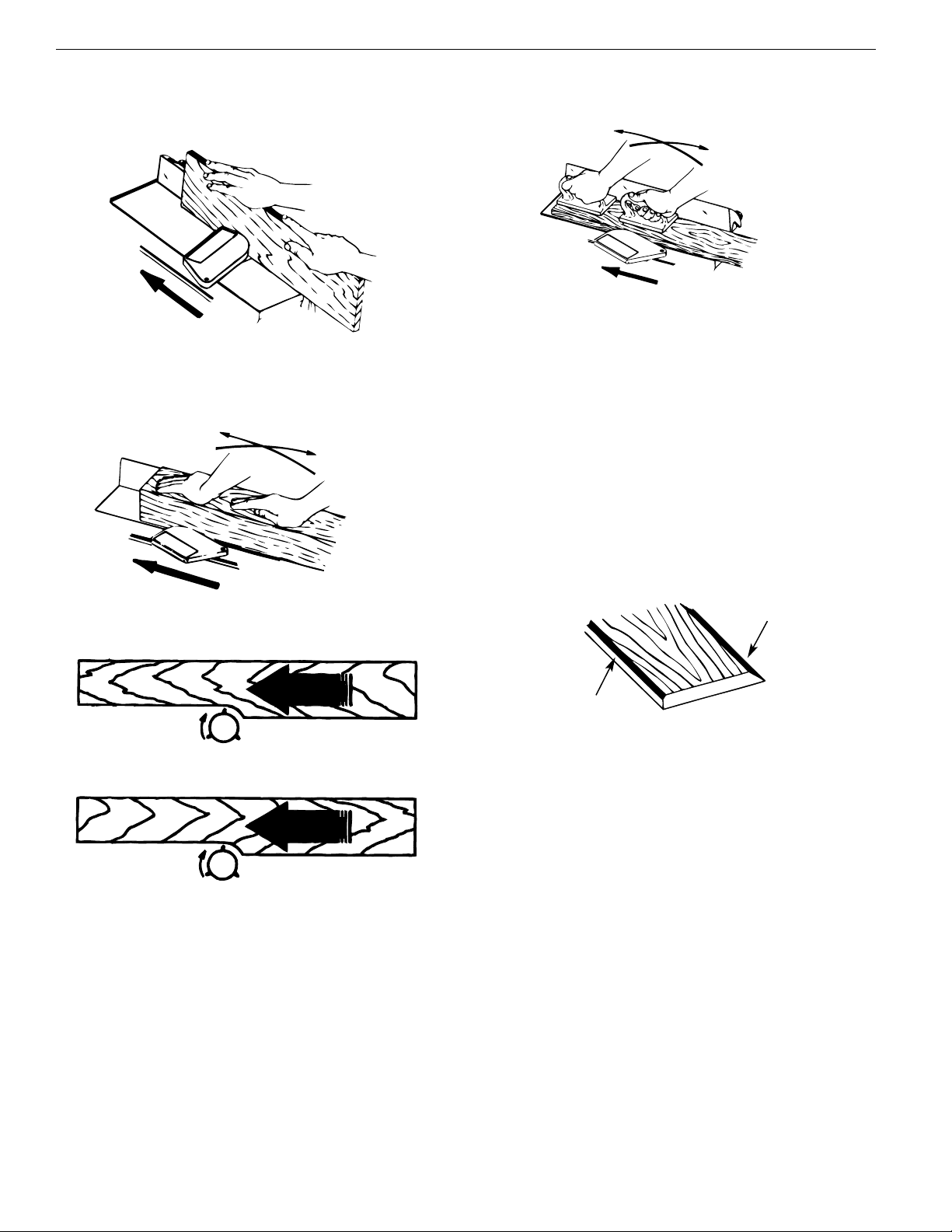
OPERATION
Refer to Figures 10-20, pages 6-8.
OPERATION SAFETY RULES
Jointing is a surfacing operation in which a small amount of wood is
removed from the edges and faces of boards to get smooth, straight
and even surfaces such that the two edges that run across the plan-
ing blocks would fit together perfectly, forming a seamless joint.
Planing refers to the sizing of lumber to a desired thickness while
creating a level surface parallel to the opposite side of the board.
Depth of cut is the term used to indicate how deep the blades will
cut into the workpiece.
WARNING: Operation of any power tool can result in foreign
objects being thrown into eyes which can result in severe eye
damage. Always wear safety goggles complying with United States
ANSI Z87.1 before commencing power tool operation.
WARNING: For your own safety, read all of the instructions and
safety precautions before operating tool.
•Know general power tool safety. Make sure all precautions are
understood (see pages 2, 3, 5 and 6).
•Whenever adjusting or replacing any parts on jointer/planer,
turn switch off and remove plug from power source.
•Make sure all guards are properly attached and securely
fastened.
•Make sure all moving parts are free from interference.
•Always wear eye protection or face shield.
•Make sure blades are aligned and properly attached to cutter-
head.
Figure 8 – 2-Prong Receptacle with Adapter
Make Sure This Is
Connected To A
Known Ground
2-Prong Receptacle
Grounding Lug
Adapter
3-Prong Plug
Figure 9 – Wiring Schematic
Green
White
To
Motor
To
Power
White
Switch
Black Black

OPERATION (CONTINUED)
•Do not plug in jointer/planer unless switch is in OFF position.
After turning switch on, allow jointer/planer to come to full
speed before operating.
•Keep hands clear of all moving parts.
•Do not force cut. Slowing or stalling will overheat motor.
•Use quality lumber. Blades last longer and cuts are smoother
with good quality wood.
•Do not perform jointing/planing operations on material shorter
than 81/8″, narrower than 3/4″, or less than 1/4″thick.
•Never make jointing cut deeper than 1/8″.
•Always keep cutterhead and blade guards in proper working
condition.
•Maintain the proper relationships of infeed and outfeed table
surfaces and cutterhead blade path.
•Do not back the work toward the infeed table.
•Support the workpiece adequately at all times during opera-
tion; maintain control of the workpiece.
•Use hold-down/push blocks for jointing material narrower than
3″or planing material thinner than 3″.
•Take precautions against kickback. Do not permit anyone to
stand or cross in line of cutterhead’s rotation. Kickback or
thrown debris will travel in this direction.
•Turn switch off and disconnect power whenever jointer/planer
is not in use.
•Replace or sharpen blades as they become damaged or dull.
•Do not attempt to perform an abnormal or little used opera-
tion without study and the use of adequate hold-down/push
blocks, jigs, fixtures, stops and the like.
•Keep jointer/planer maintained. Follow maintenance instructions
(see pages 9-10).
DEPTH OF CUT
Refer to Figure 10.
The depth of cut is adjusted by the relative positioning of the
infeed table with respect to the cutterhead. Infeed table can be
raised or lowered using the handwheel.
Turning the handwheel counterclockwise will lower the infeed
table causing more wood to be removed from workpiece. Turning
the handwheel clockwise will raise the infeed table causing less
wood to be removed from workpiece.
Do not make jointing or planing cuts deeper than 1/8″.
CHECK DEPTH OF CUT
Refer to Figure 11.
•Place a straight edge on the outfeed table extending over the
infeed table.
•Measure from the surface of the infeed table to the bottom of
the straight edge.This will be the depth of cut.
NOTE: This jointer/planer will make a maximum 1/8″deep cut. To
reduce the danger of kickback and possible injury, we recommend
taking cuts of 1/16″or less.
CAUTION: Make sure the switch is in the OFF position and the
cord is unplugged from power source before performing this
check.
POSITIONING FENCE
The fence can be adjusted to cut any angle from 0°-45° inward and
outward.The fence can be tilted inward up to 45° (toward the cut-
terhead) to maintain greater stability of a narrow workpiece or up
to 45° outward (away from cutterhead) for larger angle cutting
operations.
To adjust tilting angle:
•Loosen fence tilting handle.
•The fence tilting handle is spring loaded. To continue turning
the handle, gently pull the handle away from the fence and
return it to the original position.
•Release the handle and continue loosening.
•Manually tilt fence inward/outward to the desired angle. Use a
bevel scale or protractor to measure tilt angle.
NOTE: The fence has positive stops at 0° (90° from table), 45°
inward and 45° outward.
•Tighten fence tilting handle.
•To continue tightening, gently pull the handle away from fence
and return the handle to the original position.
•Release the handle and continue tightening.
•Make sure the fence is tight and secure.
The fence can be positioned so that any desired width of the blade
is exposed.
To adjust fence position:
•Loosen fence sliding handle.
•Slide fence forward to the desired position.
•Tighten fence sliding handle.
•Make sure fence is tight and secure.
CAUTION: Do not remove blade guard. Make sure that the cutter-
head is covered all the time.
CAUTION: Do not slide fence away from the jointer body. All
sides of the cutterhead must be covered all the time.
BLADE GUARD
The blade guard provides protection over the cutterhead. It must
always be in place and function properly.
Check the guard to make sure it functions properly. To check:
•Pass a 1/4″thick piece of wood over the cutterhead between the
guard and the fence. The guard will spread and leave way for
the wood piece to pass. The guard must return to the original
position automatically when the wood piece is removed.
•Open the blade guard all the way until it stops, and release it
several times. It should always return to its original position by
spring action.
6
Palmgren Operating Manual & Parts List 84261A
Figure 10 – Depth of Cut
Infeed Table
Depth of Cut
Hand Knob
Figure 11 – Check Depth of Cut
Outfeed
Table Max Depth
of Cut 1/8″

7
Palmgren Operating Manual & Parts List 84261A
OPERATION (CONTINUED)
CAUTION: If the blade guard fails to operate properly, the spring
must be replaced or adjusted.
•To adjust or to assemble spring see “Adjusting Blade Guard”,
page 9.
ADJUSTING BLADE HEIGHT
Refer to Figures 12-14.
CAUTION: Make sure the switch is in the OFF position and cord is
unplugged before proceeding with checking blades.
The blades have been adjusted at the factory to assure proper
operation and should require no adjustment. However, shipping
and handling may have caused misalignment. For accurate cutting,
the blades must be as high as the outfeed table when positioned
at the highest point. To check blade height:
•Block the blade guard from closing using a scrap piece of wood
about 61/4″long between the fence and blade guard.
•Turn the cutterhead so that one of the blades is at the highest
position.
CAUTION: The cutterhead blades are extremely sharp. Do not let
your fingers contact the cutting edge at any time.
•Place a straightedge over the outfeed table and the blade.
•The straightedge must touch evenly on the outfeed table at
both ends of the blade.
•Rotate the cutterhead by hand. The blades should just touch
the straightedge. If a blade is too low or too high at either end,
adjust blade height using the jack screws.
AVOID DAMAGE TO BLADES
Jointer/planer is a precision woodworking machine and should
only be used on quality lumber. Using bad lumber could result in a
poor quality cut on subsequent pieces.
For proper operation, it is preferable to use the jointer with a dust
collecting system (see “Using a Vacuum Hose”, page 8) attached to
the exhaust port in the rear of the jointer. Attaching a dust collect-
ing system is especially required when taking deeper cuts to pre-
vent clogging of wood chips.
•Do not use dirty boards. Dirt and stones are abrasive and will
wear blade.
•Remove nails and staples. Jointer should only cut wood.
•Avoid knots. Heavy cross-grain makes knots hard and they can
come loose and jam the jointer.
•Assess value of badly warped boards. Operator can be tempted
to use too deep of cut to square boards quickly. Use several
passes to maintain a level surface.
ON-OFF SWITCH
Refer to Figure 15.
The operating positions of the On-Off switch are located on the
front of your jointer/planer.
•Push the switch up to turn jointer/planer on and push down to
turn the unit off.
•The switch has a removable key that allows the unit to be
locked in the OFF position.
To activate locking mechanism:
•Push the switch to OFF position.
•Pull switch key.
To deactivate locking mechanism:
•Insert and press switch key in the slot on switch.
WARNING: Be sure the switch is in OFF position and the cord is
unplugged from the power source before removing switch key.
FEEDING WORKPIECE
Refer to Figures 16-19, page 8.
Feed rate refers to rate at which wood is passed over blades. An
even feed will produce a uniform service.To feed workpiece:
•Hold the board firmly down on both tables and against the
fence.
Blade Clamp
Cutter Head
Clamp Screw
Wood Block
Blade
Cutter Guard
Figure 12 – Block Blade Guard
Figure 13 – Checking Outfeed Table Alignment
Steel Straight Edge
Outfeed
Table
Infeed
Table
Figure 14 – Cutterhead Assembly
Cutterhead
Blade
Jack Screw
Blade Clamp
Blade Lock
Screw
Figure 15 – On-Off Switch
Switch
Switch Key

8
Palmgren Operating Manual & Parts List 84261A
OPERATION (CONTINUED)
•Keep fingers close together.
•Feed the board at a continuous even rate of speed. Any hesita-
tion or stopping could cause a “step” to be cut on the edge of
the board.
•As the trailing hand passes over the cutterhead, remove the
leading hand.
•Continue feeding while placing the leading hand behind the
trailing hand until the entire length of the board is cut.
•Feed with the grain whenever possible.
•If the nature of the workpiece is such that it must be fed
against the grain, take very light cuts and feed slowly.
•When using long workpieces, to avoid injury from slips or kick-
backs and to exert even pressure on the cutterhead, use extra
supports (see “Recommended Accessories”, page 15) at both
infeed and outfeed ends.
USING HOLD DOWN/PUSH BLOCKS
Refer to Figure 19.
•Always use hold-down/push-blocks when jointing, or rabbeting
wood that is narrower than 3″, planing wood thinner than 3″.
•Grasp the hold-down/push-blocks firmly.
•Position the push-blocks flat on top of workpiece and push the
workpiece down against the table.
•Use a hand-over-hand motion to maintain control over the
workpiece at all times.
•When planing workpiece between 1/2- 3/4″and narrower than
the push-blocks, tilt the push-blocks so that it clears the cutter-
head guard while feeding.
BEVELING AND CHAMFERING
Refer to Figure 20.
•The fence on the jointer/planer is adjustable from 45° inward to
45° outward. Adjust the fence to the desired angle and tighten
fence tilting handle.
•Beveling refers to cutting the entire edge of a board at an
angle. Beveling may require several passes due to the depth of
cut needed.
•Chamfering refers to removing only the corner of the edge of a
board. Normally a chamfer is made on one pass; so a 1/16″depth
of cut is made.
USING A VACUUM HOSE
A standard dust collection hose can be attached to the exhaust
port (21/2″Dia.) underneath the outfeed table. Jointer will perform
properly at all depths of cuts up to 1/8″when used with a dust col-
lecting system. (See “Avoid Damage to Blades”, page 7.) To attach a
dust collecting system:
•Insert the dust collection hose to the exhaust port on the rear
of the jointer.
•Turn the dust collecting system on.
•Turn the jointer on.
•Periodically replace/empty bag in dust collecting system.
FEED
FEED
Figure 18 – Direction of Feed
Rotation
With the Grain
Against the Grain
Rotation
Figure 16 – Feeding Workpiece
Figure 17 – Guiding Workpiece
Figure 19 – Feeding with Push Blocks
Figure 20 – Beveling and Chamfering
Bevel Edge
Chamfer Edge

Palmgren Operating Manual & Parts List 84261A
MAINTENANCE
WARNING: Turn the switch to OFF position and unplug
jointer/planer from power source before proceeding to do
maintenance work.
CHECKING FOR WORN BLADES
Condition of blades will affect precision of cut. If blade wear is not
observed when checking the blade height, the quality of cut will
indicate the blade condition. Dull blades will tear rather than sever
wood fiber. A raised grain will occur when dull blades pound on
wood where there is difference in density. A raised ridge will be
produced where the blades have been nicked.
SHARPENING BLADES
Refer to Figure 21.
The blades can be honed individually by whetting them with a fine
sharpening stone. Make sure oilstone is flat and is not worn.To
sharpen blades:
•Partially cover the stone with paper to protect the table top.
•Position infeed table so stone will contact blade along its
beveled surface.
•Stroke the stone across blade from one side to other while
stone is also moved slightly in the direction of feed.
•Make sure to do the same number of strokes on each place.
If the blades are nicked they must be replaced or reground.They
can be reground several times until they become 13/16″wide.
NOTE: Many shops do not have capabilities to resurface blades.
Yellow pages should list “Sharpening Services” or “Tool Grinding.”
Never install unbalanced blades or reground blades less than 13/16″
wide.
REPLACING BLADES
Refer to Figure 22.
•Unplug the jointer/planer from power source and turn the
switch to OFF position.
•Block the blade guard from closing down.
•Loosen and remove three blade lock screws securing blade and
blade clamp.
•Lift blade and blade clamp from cutterhead.
•Clean any sawdust and resin buildup from cutterhead and
blade clamp.
•Place blade clamp against the replacement blade and replace
in cutterhead.
•Secure blade and blade clamp using three blade lock screws.
Do not tighten blade lock screws.
NOTE: Check blade height at both ends of blade (see “Adjusting
Blade Height”, page 7).
•Tighten blade lock screws.
•Recheck blade adjustment and make sure blade is still level
with outfeed table.
•Repeat the procedure to replace the other blade.
•Remove the scrap wood and release blade guard.
•Make sure all the blade lock screws are tight and snug.
ADJUSTING BLADE GUARD
Refer to Figure 25, page 14.
CAUTION: Do not lubricate the pivot point of the blade guard. Oil
and lubricating products may contain chemicals that can damage
and/or destroy blade guard or other plastic parts.
The blade guard needs adjustment or spring replacement if it does
not cover the cutterhead when released.To adjust or replace
spring:
•Lay the jointer/planer on the side so that the switch is facing
upward.
•Remove four screws and bottom cover (Ref. Nos. 37 and 54).
•Loosen and remove screw, washer and spring (Ref. Nos. 13, 12
and 11) under the base that secures the blade guard.
•Slide out blade guard.
•If the spring is out of tension, it must be replaced. Remove
screw (Ref. No. 8) that retains spring.
•Replace new spring so that the short arm of the spring is held
by screw (Ref. No. 8).
•Position blade guard so that the long arm of the spring is
against the wall of the blade guard.
•Secure blade guard using spring, washer and pan head screw.
•Replace bottom cover. Secure with screws.
•Make sure blade guard functions appropriately.
REPLACING DRIVE BELT
Refer to Figures 23 and 25, pages 10 and 14.
•Turn the switch to OFF position and unplug the tool from
power source.
•Lay the jointer/planer on the side so that the switch is facing
upward.
•Remove four screws and bottom cover (Ref. Nos. 37 and 54).
•Remove two screws and access cover (Ref. Nos. 37 and 38).
•Remove fan belt (Ref. No. 31) from cutterhead pulley by turning
belt and maintaining pressure.
9
Figure 22 – Block Blade Guard
Blade Clamp
Cutter Head
Clamp Screw
Wood Block
Blade
Cutter Guard
Figure 21 – Sharpening Blades
7/8″Wide
38°
Figure 23 – Replacing Timing Belt
Remove

10
Palmgren Operating Manual & Parts List 84261A
MAINTENANCE (CONTINUED)
•Remove four bolts (Ref. No. 24) that retain motor mounting
plate (Ref. No. 49).
•Remove drive belt (Ref. No. 53).
•Replace with new drive belt. Make sure belt seats fully in
grooves of both pulleys and install motor plate to base with
the four bolts. Do not completely tighten bolts.
•Push motor assembly towards the right to apply tension to the
drive belt.Tighten bolts securely.
•Replace fan belt onto cutterhead pulley, making sure belt seats
properly in grooves of both pulleys.
•Replace access cover using two screws.
•Replace bottom cover using four screws.
REPLACING FAN BELT
•Turn the switch to OFF position and unplug the tool from
power source.
•Lay the jointer/planer on the side so that the switch is facing
upward.
•Remove four screws and bottom cover (Ref. Nos. 37 and 54).
•Remove two screws and access cover (Ref. Nos. 37 and 38).
•Loosen chip exhaust housing (Ref. No. 21) by removing two
socket head bolts (Ref. No. 24).
•Remove old fan belt and place new belt over fan pulley.
•Attach chip exhaust housing to base with the two belts.
•Pull belt over cutterhead pulley making sure the belt seats in
grooves of both pulleys.
GENERAL MAINTENANCE
Jointer/planer will operate best if it is kept in good operating con-
dition. Keep unit adjusted as described in “Operation.”
•Do not allow gum and pitch to accumulate on the tables, fence,
blades and blade guard.
•Apply a thin coat of paste type wax to the tables and the fence
so that the wood slides easily while feeding.
•Keep blades sharp (see “Sharpening Blades”, page 9). Sometimes
replacing blades is less expensive than resurfacing them.
Keeping a spare set of blades on hand is recommended. Blades
should always be sharpened or replaced in sets of two.
LUBRICATION
WARNING: Make sure the switch is in the OFF position and the
tool is disconnected from the power source.
WARNING: Do not at any time let brake fluids, gasoline, penetrat-
ing oils, etc. come in contact with plastic parts.They contain chemi-
cals that can damage and/or destroy plastics.
•Motor and cutterhead bearings are sealed and need no
lubrication.
•Fence, fence bracket and elevation screws should be cleaned of
debris and greased as needed.
MACHINED SURFACES
•Surface of tables and fence must be kept smooth and clean for
easy work feed.
•Apply a paste wax to surfaces to keep them slick and prevent
corrosion.
BRUSH INSPECTION AND REPLACEMENT
WARNING: Turn jointer off and disconnect from power source.
Brush life depends on amount of load on motor. Regularly inspect
brushes after 100 hours of use. Brushes are located on either side
of motor.
Refer to Figure 25, page 14.
•Loosen brush cap (Ref. No. 44) and remove brush (Ref. No. 45)
from motor.
•Replace brushes if springs are worn.
•Replace brushes if carbon is worn to 3/8″length or less.
NOTE: Replace brushes in sets only.
•Replace brushes and tighten brush cap.

11
Palmgren Operating Manual & Parts List 84261A
TROUBLESHOOTING
SYMPTOM
Motor does not start
Motor stalls (resulting in blown fuses or
tripped circuit breakers)
Motor starts slowly or fails to come
to full speed
Motor running too hot
Frequent opening of fuses or circuit breakers
Snipe (gouging at end of boards)
Uneven depth of cut
45° cuts inaccurate
Fuzzy grain
Torn grain
POSSIBLE CAUSES
1. Defective switch
2. Defective motor
3. Low line voltage
1. Circuit overloaded
2. Low line voltage
3. Motor overloaded
4. Incorrect fuses on circuit breakers
5. Short circuit in motor; loose connections
or worn insulation on lead wires
6. Clogged wood chips
1. Defective motor windings
2. Clogged wood chips
1. Motor overloaded
2. Restricted air circulation due to dust
accumulation
1. Motor overloaded
2. Fuses or circuit breakers do not have
sufficient capacity
3. Circuit overloaded
1. Dull blades
2. Inadequate support of long boards
3. Uneven feed
1. Blade height not uniform
2. Fence not perpendicular to jointer bed
3. Feeding wood too fast
1. Fence stops not adjusted properly
2. Fence bottom not even with outfeed table
due to wood chips under fence
Planing wood with high moisture
1. Too heavy a cut
2. Blades cutting against grain
3. Dull blades
CORRECTIVE ACTION
1. Have switch replaced
2. Have motor replaced/repaired
NOTE: 1 and 2 must be done by a qualified
service technician
3. Correct low line voltage condition
1. Reduce circuit load (turn off other
appliances)
2. Correct low line voltage conditions
3. Reduce load on motor
4. Have correct fuses or circuit breakers
installed
5. Inspect terminals in motor for damaged
insulation and shorted wires and have
them replaced
6. Take shallow depth of cut and attach a
shop-vac to exhaust port. Inspect chip
blower assembly and fan belt
1. Have motor replaced/repaired
2. Take shallow depth of cut and attach a
shop-vac to exhaust port. Inspect chip
blower assembly and fan belt
1. Reduce load on motor
2. Clean dust and restore normal air
circulation
1. Reduce load on motor
2. Have correct fuses or circuit breakers
installed
3. Reduce circuit load (turn off other
appliances)
1. Replace or sharpen blades. See
“Sharpening Blades,” page 9
2. Support long boards. See “Recommended
Accessories,” page 15
3. See “Feeding Workpiece,” page 7
1. Adjust blade height. See “Adjusting Blade
Height,” page 7
2. See “Install Fence and Fence Bracket to
Jointer,” page 3
3. Feed wood slower
1. Adjust fence stops. See “Install Fence and
Fence Bracket to Jointer,” page 3
2. Clean wood chips from underside of fence
Remove high moisture content from wood
by drying
1. Reduce depth of cut
2. Feed work along grain
3. Replace or sharpen blades

4
36
35
3
16
45
47
29
2
3
3
13 12
12
18
21
20
22
23
24
25
26
27
30
31
9
8
33
4
42
28
44
43
14
38
56
8
6
17
14
19
11
9
3
32
41
7
2
15
1
10
40
46
37
39
12
Palmgren Operating Manual & Parts List 84261A
Figure 24 – Replacement Parts Illustration for Fence and Infeed Table

13
Palmgren Operating Manual & Parts List 84261A
REPLACEMENT PARTS LIST FOR FENCE AND INFEED TABLE
* Standard hardware item available locally.
ΔNot Shown
Ref.
No. Description Part No. Qty.
1 Fence 18963.09 1
2 5-0.8mm Hex Nut * 2
3 6-1.0mm Hex Nut * 4
4 5-0.8 x 25mm Hex Head Bolt 18954.00 2
5 Handle 18410.00 1
6 Spacer 18454.00 2
7 Fence Plate 18411.09 1
8 8mm Lock Washer * 6
9 8-1.25 x 20mm Socket Head Bolt * 6
10 Plate Shaft 18412.00 1
11 Right Link 18413.00 1
12 10mm Push Nut 18414.00 2
13 6-1.0 x 20mm Socket Head Bolt * 4
14 6mm Lock Washer * 8
15 Bracket Shaft 18415.00 1
16 Left Link 18416.00 1
17 Fence Bracket 18417.09 1
18 6-1.0 x 50mm Socket Head Bolt 06101.00 1
19 Limit Plate 18418.00 1
20 Shaft 18419.00 1
21 Block 18420.00 1
22 Handle 25142.00 1
23 Infeed Table 18422.09 1
24 Bracket 18423.00 4
Ref.
No. Description Part No. Qty.
25 Table Pin 18424.00 4
26 Frame Pin 18425.00 4
27 Fence Support 25143.00 1
28 Pin 18427.00 2
29 Locking Plate 25144.00 1
30 8-1.25mm Hex Nut * 1
31 8-1.25 x 35mm Hex Head Bolt 00979.00 1
32 Table Frame 18965.00 1
33 3CMI-6 E-ring 09845.00 4
34 6-1.0 x 30mm Set Screw 09721.00 1
35 6-1.0 x 35mm Set Screw 05224.00 1
36 Support Plate 18430.00 1
37 5mm Lock Washer * 2
38 5-1.0 x 16mm Set Screw 03855.00 2
39 Knob 18431.00 1
40 Elevation Screw 18432.00 1
41 5mm Flat Washer * 1
42 6-1.0 x 16mm Set Screw 01640.00 4
43 6mm Flat Washer * 4
44 5-0.8 x 10mm Pan Head Screw 01784.00 1
45 6-1.0 x 30mm Socket Head Bolt 18955.00 4
46 Push Block (set of 2) 02848.00 1
47 6-1.0 x 30mm Set Screw 09721.00 1

43
36
35
23
16
45
45 47
29
2
12
6
13
13
12
18
21 20
22
22
23
24
24
25
26
27
30
31
9
8
1
33
4
42
28
44
44
34
37
14
38
5
8
2
17
19
11
3
32
41
13
23
7
29
29
15
10
40
46
46
49
50
51
52
53
54
48
37
37
39
14
Palmgren Operating Manual & Parts List 84261A
Figure 25 – Replacement Parts Illustration for Base

15
Palmgren Operating Manual & Parts List 84261A
REPLACEMENT PARTS LIST FOR BASE
Ref.
No. Description Part No. Qty.
1 Base with Outfeed Table N/A 1
2 6201ZZ Ball Bearing 00520.00 2
3 3AMI-12 Retaining Ring 00519.00 1
4 Strain Relief 08077.00 1
5 Line Cord 00090.00 1
6 Spring 18440.00 1
7 Pin 18441.00 1
8 4-0.7 x 10mm Pan Head Screw 01903.00 3
9 Bumper 18958.00 1
10 Blade Guard 18957.00 1
11 Spring 18964.00 1
12 Washer 00968.00 2
13 5-0.8 x 10mm Socket Head Bolt 03855.00 6
14 Chip Collector 18959.00 1
15 5mm Flat Washer * 3
16 5-0.8 x 10mm Pan Head Screw 01784.00 3
17 Chip Exhaust 18960.00 1
18 Dust Chute 18962.00 1
19 6-1.0 x 20mm Pan Head Screw * 1
20 Impeller 18449.00 1
21 Chip Blower Mounting Plate 18448.00 1
22 6mm Flat Washer * 5
23 6mm Lock Washer * 6
24 6-1.0 x 12mm Socket Head Bolt 01505.00 5
25 Thread Forming Screw 18462.00 6
26 Fan Shaft 18447.00 1
27 Spacer 18446.00 1
28 6000ZZ Ball Bearing 04018.00 2
29 6-1.0 x 8mm Set Screw 01043.00 5
Ref.
No. Description Part No. Qty.
30 Fan Pulley 18445.00 1
31 Fan Belt 18444.00 1
32 1/4-20 x 5/8’’ Socket Head 18455.00 8
Pan Screw
33 Blade Clamp 18456.00 2
34 Blade (set of 2) 18457.00 1
35 Cutterhead 18458.00 1
36 Drive Pulley 18460.00 1
37 5-0.8 x 8mm Pan Head Screw 06701.00 10
38 Access Cover 18461.09 1
39 Jack Screw 18459.00 4
40 Shaft 18443.00 1
41 Switch 16080.00 1
42 Switch Plate 18442.09 1
43 4mm Serrated Washer 05156.00 2
44 Brush Cap 02861.00 2
45 Carbon Brush (set of 2) 02862.00 1
46 Brush Holder 02863.00 2
47 Motor 18433.00 1
48 Motor Pulley 18434.00 1
49 Motor Mounting Plate 18436.00 1
50 5mm Lock Washer * 4
51 Cord Clamp 02621.00 1
52 6-1.0 x 16mm Socket Head Bolt * 1
53 Drive Belt 18438.00 1
54 Cover 18961.00 1
ΔHalf Bag Dust Collection Set 18625.09 1
ΔOperator’s Manual 25164.09 1
* Standard hardware item available locally.
ΔNot Shown
N/A Not Available
Recommended Accessories
ΔBlade (set of 2) 18457.00

Palmgren Operating Manual & Parts List 84261A
TWO YEAR LIMITED WARRANTY
Palmgren warrants to the original purchaser that all products covered under this warranty are free from defects in material and workman-
ship for a period of two years from the date of the original purchase.
We will repair or replace at our option, any part or parts of the product and accessories covered under this warranty which, after examina-
tion, proves to be defective in workmanship or material during the warranty period.
This warranty does not apply to repair or replacement required due to misuse, abuse, normal wear and tear, or repairs attempted or made by
other than our Service Department or an Authorized Service Representative. Proper use and care instructions are provided in the operator’s
manual. Failure to follow these instructions will void the warranty.
This warranty gives you specific legal rights and you may also have other legal rights which may vary from state to state.
Responsibility of Original Purchaser (Initial User):
•To process warranty claim on this product, DO NOT return it to the retailer. The product must be evaluated by Palmgren.
Call (800) 621-6145 for instructions.
•Retain original cash register sales receipt or invoice as proof of purchase for warranty work.
•Use reasonable care in the operation and maintenance of the product as described in the operator’s manual.
•Deliver or ship the product(s) to Palmgren. Freight costs, if any must be paid by the purchaser.
This Warranty Does Not Cover:
•Merchandise sold as reconditioned, used as rental equipment, and floor or display models.
•Repair and transportation costs of merchandise determined not to be defective.
•Expendable parts or accessories supplied with the product which are expected to become inoperative or unusable after a reasonable
period of use. See the operator’s manual for a list of accessories and expendable parts.
Table of contents
Other Palmgren Power Tools manuals

Palmgren
Palmgren 80171 User manual

Palmgren
Palmgren MTC18 User manual

Palmgren
Palmgren 9661614 Instructions for use

Palmgren
Palmgren 80174 User manual

Palmgren
Palmgren 9661610 Instructions for use

Palmgren
Palmgren 80110B User manual

Palmgren
Palmgren 80341A User manual

Palmgren
Palmgren 9680130 User manual

Palmgren
Palmgren 61051C User manual

Palmgren
Palmgren 32806 User manual

Palmgren
Palmgren 80207 User manual

Palmgren
Palmgren 0.5-Ton Arbor Press User manual

Palmgren
Palmgren 80329 User manual

Palmgren
Palmgren 9661104 User manual

Palmgren
Palmgren 61101C User manual

Palmgren
Palmgren 80150 User manual

Palmgren
Palmgren 80206 User manual

Palmgren
Palmgren 80110A User manual

Palmgren
Palmgren 80177 User manual