ProScan PLDEDV3283-B User manual


1
2
3
3
Remote Control
4
Front View
6
Back View
6
Side View
7
Antenna Connection
8
AV Connection
8
YPbPr Connection
9
HDMI Connection
9
VGA Connection
10
Headphone Connection
10
Power Cord Connection
10
Coax(SPDIF) Connection
11
12
13
13
13
15
17
19
20
23
26
27
CONTENTS
English
SAFETY
PRECAUTION
CONNECTIONS
ACCESSORIES
IMPORTANT
SAFETY
INSTRUCTION
2
1
3
6
GETTING
STARTED
4
CONTROL
REFERENCE
GUIDE
5

28
29
32
34
35
37
38
39
40
41
42

1
*
CAUTION MARKING WAS LOCATED AT THE REAR
PLACEMENT INFORMATION
OF THE APPARATUS.
WARNING:TO REDUCE THE RISK OF ELECTRIC
SHOCK
,
DO NOT REMOVE COVER
(
OR BACK
)
NO USER SERVICEABLE PARTS INSIDE
.
REFER SERVICING TO QUALIFIED SERVICE
PERSONNEL.
The lightning flash with arrowhead symbol,
within an equilateral triangle,is intended to
alert the user to the presence of uninsulated
“dangerous voltage”within the product's enclosure
that may beof sufficient magnitude to constitute a
risk of electric shock to persons.
The exclamation point within an equilateral
Triangle is intended to alert the user to
The presence of important operating and
maintenance (servicing) instructions in the literature
accompanying the appliance.
CAUTION
•
Do not use this unit in places that are extremely
hot, cold, dusty or humid.
•
Do not restrict the air low o this unit by placing it
somewhere with poor air low, by covering it with
a cloth, by placing it on bedding or carpeting.
SAFETY INFORMATION
•
When connecting or disconnecting the AC power
cord, grip the plug and not the cord itsel . Pulling
the cord may damage it and create a hazard.
•
When you are not going to use the unit or a long
period o time, disconnect the AC power cord.
CONDENSATION INFORMATION
•
When le t in a heated room where it is warm and
damp, water droplets or condensation may orm
inside the equipment. When there is condensation
inside the unit, the unit may not unction normally.
Let the unit stand or 1-2 hours be ore turning the
power on or gradually heat the room and let the
unit dry be ore use.
RATING PLATE LOCATION
The rating plate is located on the rear o the unit.
FCC STATEMENTS
NOTE: This unit has been tested and ound to comply
INVISIBLE LASER RADIATION WHEN
OPEN AND INTERLOCKS DEFEATED
AVOID EXPOSURE TO BEAM
CAUTION
This product
Contains a low
power laser device.
CLASS 1 LASER
PRODUCT
with the limits or a Class B digital device, pursuant
to Part 15 o the FCC Rules. These limits are designed
to provide reasonable protection against harm ul
inter erence in a residential installation.
This unit generates, uses and can radiate radio
requency energy and, i not installed and used in
•
DANGER OF EXPLOSION IF BATTERY IS
INCORRECTLY REPLACED. REPLACE ONLY
WITH THE SAME OR EQUIVALENT TYPE.
•
USE OF CONTROLS OR ADJUSTMENTS OR
PERFORMANCE OF PROCEDURES OTHER
THAN THOSE SPECIFIED MAY RESULT IN
HAZARDOUS RADIATION EXPOSURE.
WARNING
:
•
TO REDUCE THE RISK OF FIRE OR ELECTRIC
SHOCK, DO NOT EXPOSE THIS APPLIANCE TO
RAIN OR MOISTURE.
TO REVENT FIRE OR SHOCK HAZARD, DO NOT
•
EXPOSE THIS UNIT TO RAIN OR MOISTURE. DO
NOT PLACE OBJECTS FILLED WITH LIQUIDS ON
OR NEAR THIS UNIT.
•
SHOULD ANY TROUBLE OCCUR, DISCONNECT
THE AC POWER CORD AND REFER SERVICING
TO A QUALIFIED TECHNICIAN.
“
HDMI, the HDMI logo and High-Definition Multimedia
Interface are trademarks or registered trademarks of
HDMI Licensing LLC.”
accordance with the instructions, may cause harm ul
inter erence to radio communication. However, there
is no guarantee that inter erence will not occur in a
particular installation. I this unit does cause harm ul
inter erence to radio or television reception, which
can be determined by turning the unit o and on, the
user is encouraged to try to correct the inter erence
by one or more o the ollowing measures:
-
Reorient or relocate the receiving antenna.
-
Increase the separation between the unit and
receiver.
-Connect the unit into an outlet on a circuit di erent
rom that to which the receiver is connected.
-
Consult the dealer or an experienced radio/TV
technician or help.
WARNING
:
Changes or modifications to this
unit not expressly approved by the party responsible
for compliance could void the user authority
to operate the unit.
SAFETY PRECAUTION

2
1)Read these instructions.
2)Keep these instructions.
3)Heed all warnings.
4)
Follow all instructions.
5)
Do not use this apparatus near
water. 6)Clean only with a dry cloth.
7)
Do not block any ventilation
openings. Install in accordance with
the manu acturer's instructions.
8)
Do not install near any heat sources
such as radiators, heat registers, stoves,
or other apparatus (Including ampli iers)
that produce heat.
9)
Do not de ect the sa ety purpose
o the polarized or grounding-type
plug.
A polarized plug has two blades with one
wider than the other.
A groundingtype plug has two blades
and a third grounding prong.
The wide blade or the third prong is
provided or your sa ety.
I the provided plug does not it into your
wall outlet, consult an electrician or
replacement o the obsolete outlet.
10)
Protect the power cord rom being walked on
or pinched particularly at plugs, convenience
receptacles, and the point where they exit
rom the apparatus.
11)
Only use attachments / accessories speci ied
by the manu acturer.
12)
Use only with the cart, stand,
tripod, bracket, or table
speci ied by the manu acturer,
or sold with the apparatus.
When a cart is used, use caution when
moving the cart / apparatus combination to
avoid injury rom tip-over.
13)
Unplug this apparatus during lightning
Storms or when unused or long periods o
time.
14)
Re er all servicing to quali ied service
personnel. Servicing is required when the
apparatushas been damaged in any way,
such as the power cord or plug is damaged,
liquid has been spilled or objects have allen
into the apparatus, the apparatus has been
exposed to rain or moisture, does not operate
normally, or has been dropped.
15)
To prevent electric shock, ensure the grounding
pin on the AC cord power plug is securely
connected.
Energy saving mode
IMPORTANT SAFETY INSTRUCTIONS
3
ACCESSORIES
Please check and identify the supplied accessories.
Remote con tr ol .......... ....... ....... ....... ...... ....... ...... ....... ....... ....... ... ....... ....... ....... ....... ....... ..... x 1
Battery(AAA).................................................................................................................... x 2
Warranty Card ................................................................................................................ x 1
Instruction Manual........................................................................................................... x 1
2 Base stands and 4 base stand screws
......................................................................... x 1
USING THE REMOTE CONTROL
·
Point the remote control at the remote sensor located on the unit.
·
When there is a strong ambient light source, the per ormance o the in rared remote sensor
·
may be degraded, causing unreliable operation.
·
The recommended e ective distance or remote operation is about 16 eet (5 meters).
TO INSTALL THE BATTERIES
1. Open the battery door
.
BATTERY REPLACEMENT
When the batteries become weak, the operating distance o the remote control is greatly
reduced and you will need to replace the batteries.
CAUTION
: Danger o explosion i battery is incorrectly replaced.
NOTES
·
I the remote control is not going to be used or a long time, remove the batteries to avoid
damage caused by battery leakage corrosion.
·
Do not mix old and new batteries.Do not mix ALKALINE, standard (CARBON-ZINC) or
rechargeable (NICKEL-CADMIUM) batteries.
·
Always remove batteries as soon as they become weak.
·
Weak batteries can leak and severely damage the remote control.
WARNING :
Do not dispose batteries in a ire. Batteries may explode or leak.
Batteries shall not be exposed to excessive heat such as sunshine, ire or the like.
GETTING STARTED

,
,

CONTROL
REFERENCE
GUIDE
6
FRONT VIEW
1.
Color Screen
2.Remote Sensor
Do not block this sensor or the
remote control will not work.
3.
Standby Indicator
Indicates whether the unit is ON
or in ST NDBY (OFF) mode.
Light in red: The unit is in ST NDBY.
Light in
blue
:The unit is turned ON.
4.
Speakers
BACK VIEW
1.
Power Cord
2.Headphone Jack
3.Coax OUT Jack
4.AV IN Jack
5.
COMPONENT IN Jack
6.
HDMI IN Jacks
7.VGA IN Jack
8.
PC ADUIO IN Jack
9.
TV ANTENNA Terminal
10.Service Port
6
6
9
6
1
CONTROL
REFERENCE
GUIDE
7
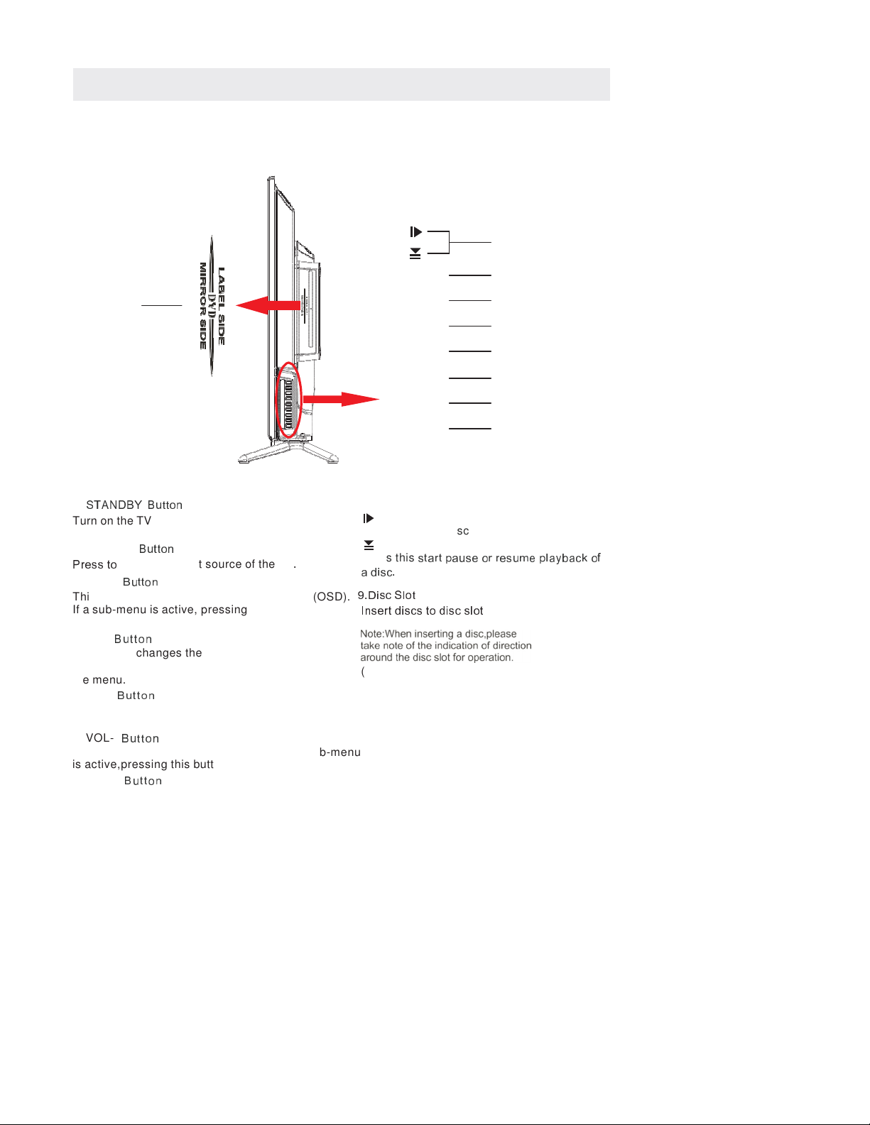
SIDE VIEW
8
VOL+
7
9
VOL-
6
CH+
5
CH-
4
MENU
3
SOURCE
2
STANDBY
1
1.
STAND Y utton
Turn on the TV by pressing the button once.
Press the button again to turn off the TV.
2. SOURCE
utton
Press to
select the input source of the TV
.
3. MENU
utton
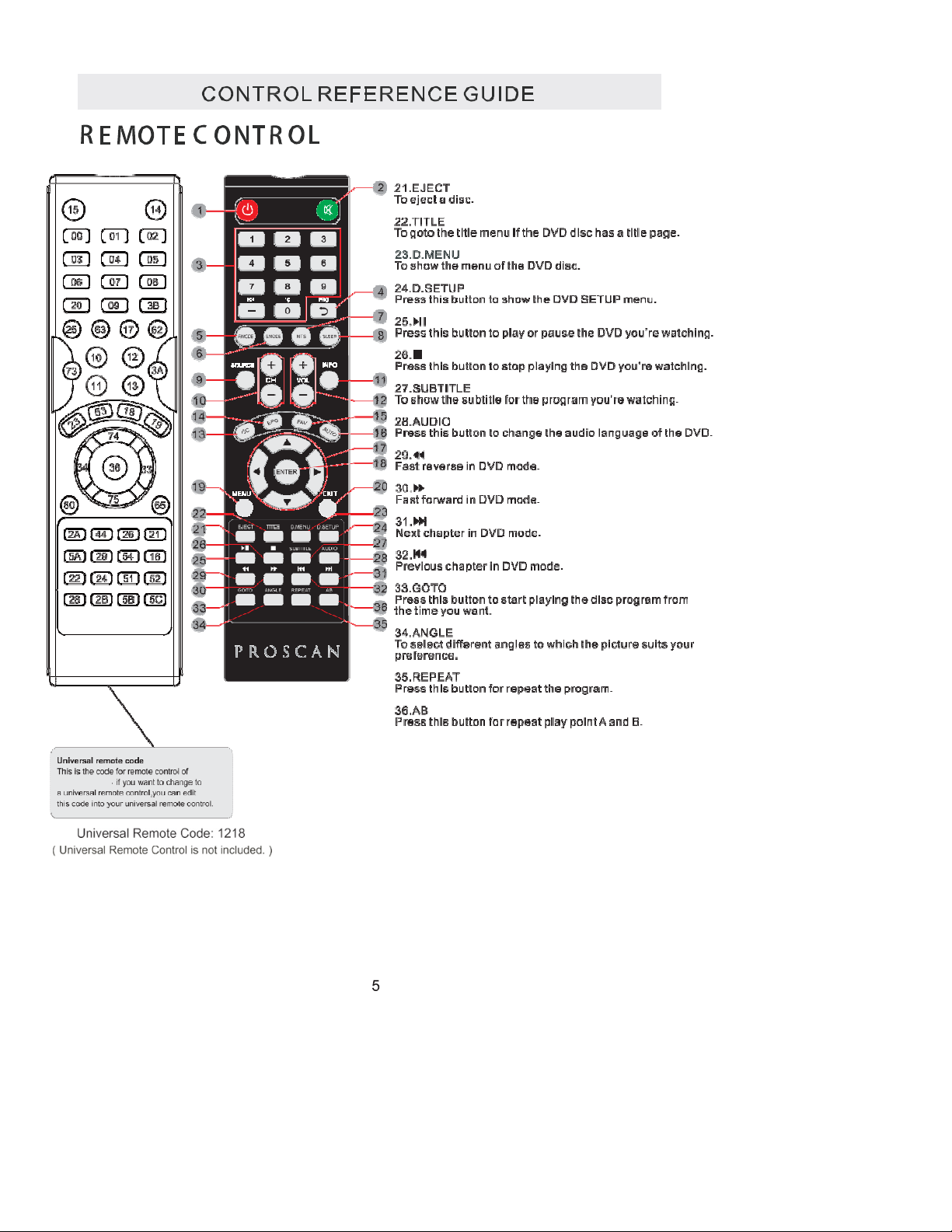
8.
Press to eject a disc.
Press this
start pause or resume playback of
a disc.
This button activates the On Screen Display (OSD).
9.Disc Slot
If a sub-menu is active, pressing this button will
exit the OSD.
4. CH-
utton
This button changes the TV channel down.If the
OSD is active,this button functions as down for
the menu.
5. CH+
utton
This button changes the TV channel up.If the OSD
is active,this button functions as up for the menu.
6. VOL-
utton
Insert discs to disc slot
(Right direction:put the mirror side of
the disc facing yourself)
This button decreases the TV's volume.If a sub-menu
is active,pressing this button will move the selection left.
7. VOL+
utton
This button increases the TV's volume.If a sub-menu is
active,pressing this button will move the select right.
8
CONNECTIONS
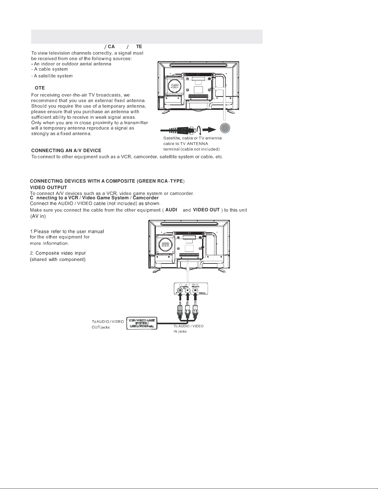
CONNECTING A TV ANTENNA
/
CABLE
/
SATELLITE
To view television channels correctly, a signal must
be received from one of the following sources:
-
An indoor or outdoor aerial antenna
-
A cable system
-
A satellite system
NOTE
For receiving over-the-air TV broadcasts, we
recommend that you use an external fixed antenna.
Should you re uire the use of a temporary antenna,
please ensure that you purchase an antenna with
sufficient ability to receive in weak signal areas.
Only when you are in close proximity to a transmitter
will a temporary antenna reproduce a signal as
strongly as a fixed antenna.
CONNECTING AN A/V DEVICE
Satellite, cable or TV antenna
cable to TV ANTENNA
terminal (cable not included)
To connect to other e uipment such as a VCR, camcorder, satellite system or cable, etc.
CONNECTING DEVICES WITH A COMPOSITE (GREEN RCA
-
TYPE
)
VIDEO OUTPUT
To connect A/V devices such as a VCR, video game system or camcorder.
Connecting to a VCR / Video Game System / Camcorder
Connect the AUDIO / VIDEO cable (not included) as shown.
Make sure you connect the cable from the other e uipment (
AUDIO
and
VIDEO OUT
) to this unit
(AV in)
NOTE
1.
Please refer to the user manual
for the other e uipment for
more information.
2.
Composite video input
(shared with component)
To AUDIO / VIDEO
OUT jacks
To AUDIO / VIDEO
IN jacks
9
CONNECTIONS
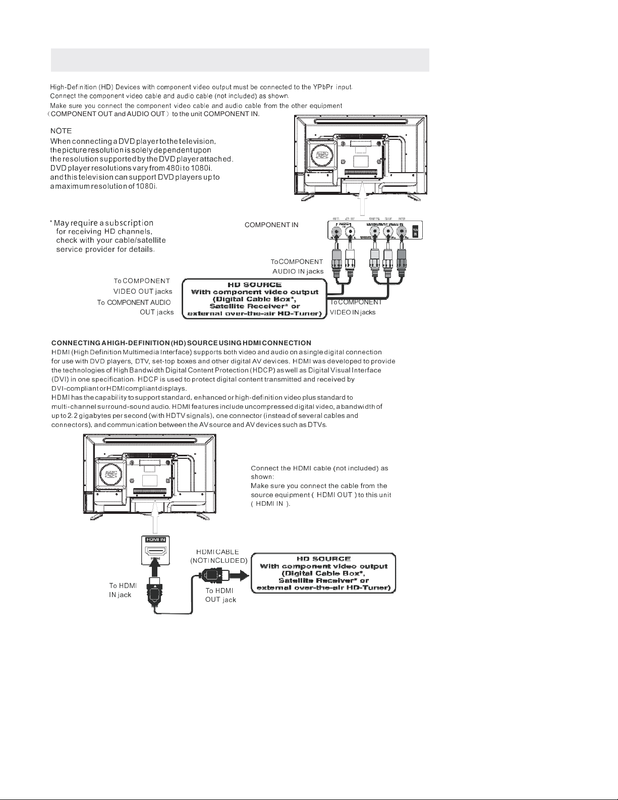
CONNECTING A HIGH-DEFINITION (HD) SOURCE USING COMPONENT CONNECTION
High-Definition (HD) Device with component video output mu t be connected to the YPbPr input.
Connect the component video cable and audio cable (not included) a hown.
Make ure you connect the component video cable and audio cable from the other equipment
(
COMPONENT OUT and AUDIO OUT
)
to the unit COMPONENT IN.
NOTE
When connecting a DVD player to the television,
the picture resolution is solely dependent upon
the resolution supported by the DVD player attached.
DVD player resolutions vary from 480i to 1080i.
and this television can support DVD players up to
a maximum resolution of 1080i.
* M
ay
r
equire
a s
ubscription
for receiving HD channels,
check with your cable/satellite
service provider for details.
To COMPONENT
VIDEO OUT jacks
To COMPONENT AUDIO
OUT jacks
COMPONENT IN
To COMPONENT
AUDIO IN jacks
To COMPONENT
VIDEO IN jacks
CONNECTING AHIGH-DEFINITION (HD) SOURCE USING HDMI CONNECTION
HDMI (High De inition Multimedia Inter ace) supports both video and audio on a single digital connection
or use with DVD players, DTV, set-top boxes and other digital AV devices. HDMI was developed to provide
the technologies o High Bandwidth Digital Content Protection (HDCP) as well as Digital Visual Inter ace
(DVI) in one speci ication. HDCP is used to protect digital content transmitted and received by
DVI-compliant or HDMIcompliant displays.
HDMI has the capability to support standard, enhanced or high-de inition video plus standard to
multi-channel surround-sound audio. HDMI eatures include uncompressed digital video, a bandwidth o
up to 2.2 gigabytes per second (with HDTV signals), one connector (instead o several cables and
connectors), and communication between the AV source and AV devices such as DTVs.
Connect
the
HDMI
cable
(not
included)
as
shown:
Make sure you connect the cable rom the
source equipment ( HDMI OUT ) to this unit
( HDMI IN ).
HDMI
CABLE
(NOT INCLUDED)
To
HDMI
IN jack
To
HDMI
OUT
jack
CONNECTIONS
10
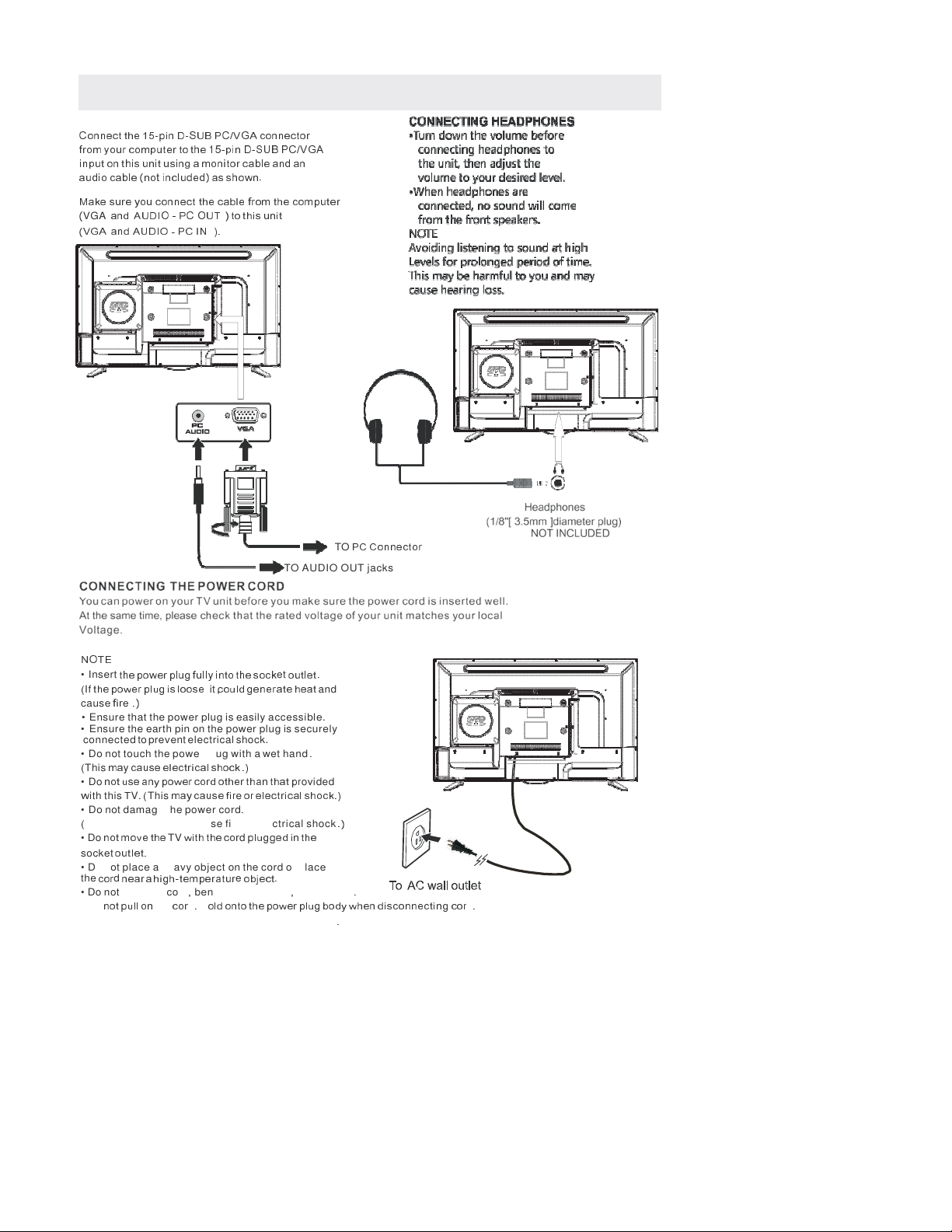
CONNECTING A PC
Connect the 15-pin D-SUB PC/VGA connector
rom your computer to the 15-pin D-SUB PC/VGA
input on this unit using a monitor cable and an
audio cable (not included) as shown.
Make sure you connect the cable rom the computer
(
VGA
and AUDIO - PC OUT ) to this unit
(VGA and AUDIO - PC IN ).
TO
PC Connector
TO AUDIO OUT jacks
NOTE
•
Insert
the power plug ully into the sock
et
outlet .
(
If
the power plug is loose
it
,could generate heat
and
cause
ir
e
.)
•
Ensure that the power plug is easily accessible.
•
Ensure the earth pin on the power plug is securely
connected to prevent electrical shock.
•
Do not touch the power plug with a wet hand
.
(
This
may cause electrical shock .)
•
Do
not use any power cord other than that pr
ovided
w
ith this
T
V
. (
This
may cause ir
e
or electrical shock.)
•
Do not damage the power cord
.
(
A damaged cord may cause fire or electrical shock
.)
•
Do
not move the
TV
with the cor
d
plugged in the
socket
outlet.
•
Do not place a heavy object on the cord or place
the
cor
d
near a high-temperatur
e
object.
•
Do not twist the cord
,
bend it excessively
,
or stretch it
.
•
Do
not pull on
the
cor
d
.
H
old onto the power plug body when disconnecting cor
d
.
•
Do not use a damaged power plug or socket outlet
.
CONNECTIONS
11
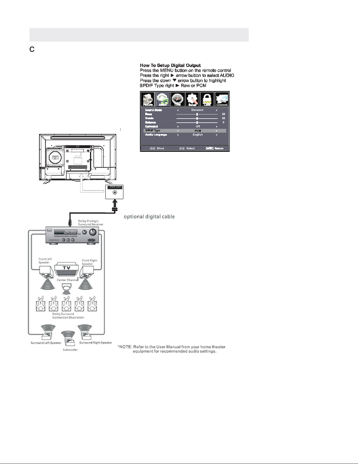
Connection to a Home Theater Audio System
For BEST audio performance
Connecting to a Home Theater System
Dolby Digital can deliver optimal 2 channel
stereo or surround sound with five discrete
full range channels plus a sixth channel for
a subwoofer.
Enjoy optimal sound reproduction from your
system with a Dolby Digital amplifier that
incorporates a digital coaxial input. Connect
an optional digital cable directly to the
television’s Coax audio output to listen
through all inputs except VGA.
(The VGA does not support digital audio
)
SPD IF OUT
Coax

12
INSTALLING
/
REMOVING
THE BASE STAND
WARNING
: The
TV D
isplay
i
s
v
ery
f
ragile a
,
nd
m
ust
b
e
p
rotected
a
t
a
ll
t
imes
w
hen
r
emoving
t
he
b
ase
Stand .
Be
sur
e
that no har
d
or sharp object
or
anything that
could
scrat
ch
or
damage
the
TV
display
comes
into
contact with it D
.
o NOT exert pressure on the front of the unit at any time because the screen could crack
.
1.
.
Disconnect
all cables or cor
ds
connected t
o
the unit.
2.
.
Lay the unit down on a flat surface with the back side facing
down.
3.
.
To remove the base stand lo
,
osen screws off the holes then pull downwards to
release the base stand
.
MOUNTING ON THE WALL
4
(
200mm
x 100mm) mounting kit designed or lat-
panel
TVs (
not
supplied). Mount
this
unit accor
ding
t
o
the
instructions included in the mounting kit.
Length of screw should not exceed 8 mm.
NOTE
Remove the base stand be ore mounting the unit on the wall.
8”
4”
M6
WALL MOUNT INSTALLATION

TV
Component/AV
DVD
HDMI1
HDMI2
HDMI3
VGA
/
14
&
KDQQH
O
/
L
V
W
&
KDQQH
O
/
L
V
W

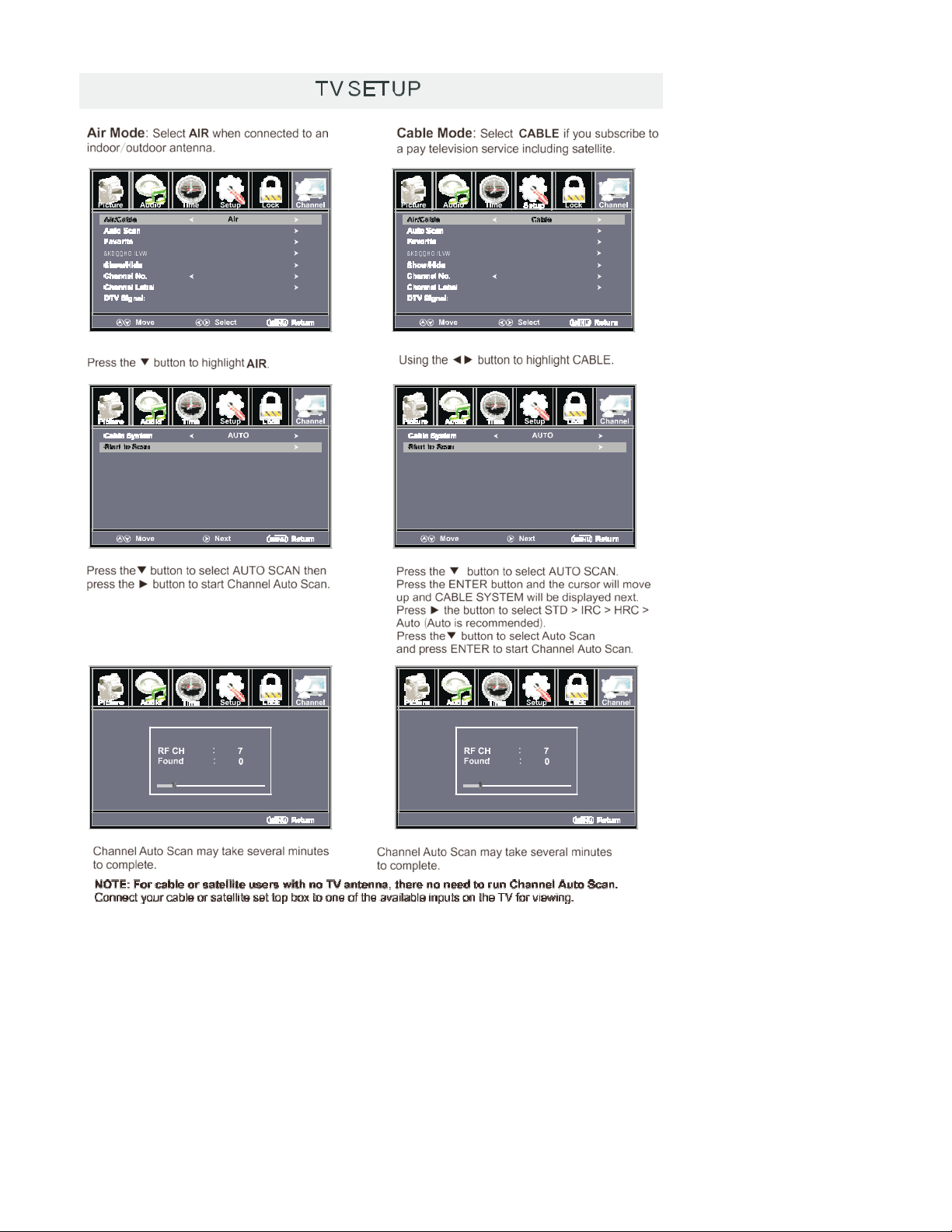
TV
S
ETUP
16

TV
S
ETUP
17
Table of contents
Other ProScan TV DVD Combo manuals


