Memorex MVDT2002SM User manual

SERVICE MANUAL
MVDT2002
Design and specifications are subject to change without notice.
COLOR TELEVISION/VIDEO CASSETTE RECORDER/
DVD VIDEO PLAYER
ORIGINAL
MFR’S VERSION A
SC

A1-1
SERVICING NOTICES ON CHECKING
6. AVOID AN X-RAY1. KEEP THE NOTICES
As for the places which need special attentions,
they are indicated with the labels or seals on the
cabinet, chassis and parts. Make sure to keep the
indications and notices in the operation manual.
3. USE THE DESIGNATED PARTS
5. TAKE CARE TO DEAL WITH THE
CATHODE-RAY TUBE
In the condition that an explosion-proof
cathode-ray tube is set in this equipment, safety
is secured against implosion. However, when
removing it or serving from backward, it is
dangerous to give a shock. Take enough care
to deal with it.
Safety is secured against an X-ray by consider-
ing about the cathode-ray tube and the high
voltage peripheral circuit, etc.
Therefore, when repairing the high voltage pe-
ripheral circuit, use the designated parts and
make sure not modify the circuit.
Repairing except indicates causes rising of high
voltage, and it emits an X-ray from the cathode-
ray tube.
HOW TO ORDER PARTS
PERFORM A SAFETY CHECK AFTER
SERVICING
7.
Confirm that the screws, parts and wiring which
were removed in order to service are put in the
original positions, or whether there are the
portions which are deteriorated around the
serviced places serviced or not. Check the
insulation between the antenna terminal or
external metal and the AC cord plug blades.
And be sure the safety of that.
(INSULATION CHECK PROCEDURE)
1.
2.
3.
4.
Unplug the plug from the AC outlet.
Remove the antenna terminal on TV and turn
on the TV.
Insulation resistance between the cord plug
terminals and the eternal exposure metal
[Note 2] should be more than 1M ohm by
using the 500V insulation resistance meter
[Note 1].
If the insulation resistance is less than 1M
ohm, the inspection repair should be
required.
[Note 1]
If you have not the 500V insulation
resistance meter, use a Tester.
[Note 2]
External exposure metal:Antenna terminal
Earphone jack
2. AVOID AN ELECTRIC SHOCK
There is a high voltage part inside. Avoid an
electric shock while the electric current is
flowing.
The parts in this equipment have the specific
characters of incombustibility and withstand
voltage for safety. Therefore, the part which is
replaced should be used the part which has
the same character.
Especially as to the important parts for safety
which is indicated in the circuit diagram or the
table of parts as a mark, the designated
parts must be used.
4. PUT PARTS AND WIRES IN THE
ORIGINAL POSITION AFTER
ASSEMBLING OR WIRING
There are parts which use the insulation
material such as a tube or tape for safety, or
which are assembled in the condition that
these do not contact with the printed board.
The inside wiring is designed not to get closer
to the pyrogenic parts and high voltage parts.
Therefore, put these parts in the original
positions.
Please include the following informations when you order parts. (Particularly the VERSION LETTER.)
1. MODEL NUMBER and VERSION LETTER.
The MODEL NUMBER can be found on the back of each product and the VERSION LETTER can be
found at the end of the SERIAL NUMBER.
2. PART NO. and DESCRIPTION
You can find it in your SERVICE MANUAL.

Before removing Pick Up PCB and DVD PCB connector, short circuit the position shown in Fig. 1
using a soldering iron. If you remove the DVD Deck with no soldering, the Laser may be damaged.
WHEN REPLACING DVD DECK
[ Removing the DVD Deck ]
A1-2
The laser diode used for a pickup head may be destroyed with external static electricity.
Moreover, even if it is operating normally after repair when static electricity discharge is received
at the time of repair, the life of the product may be shortened.
Please perform the following measure against static electricity, be careful of destruction of a
laser diode at the time of repair.
• Place the unit on a workstation equipped to protect against static electricity, such as conductive
mat.
• Soldering iron with ground wire or ceramic type is used.
• A worker needs to use a ground conductive wrist strap for body.
PREPARATION OF SERVICING
[ Installing the DVD Deck ]
Remove all the soldering on the short circuit position after the connection of Pick Up PCB and DVD
PCB connector.
NOTE
Before your operation, please read “PREPARATION OF SERVICING”.
Use the Lead Free solder.
Manual soldering conditions
• Soldering temperature: 320 ±20˚C
• Soldering time: Within 3 seconds
• Soldering combination: Sn-3.0Ag-0.5Cu
When Soldering/Removing of solder, use the drawing equipment over the Pick Up Unit to keep the
Flux smoke away from it.
•
•
•
•
Fig. 1
Short circuit using a
soldering iron.
Pick Up PCB

A1-3
PARENTAL CONTROL - RATING LEVEL
4 DIGIT PASSWORD CANCELLATION
If the stored 4 digit password in the Rating Level menu needs to be cancelled, please follow the steps below.
Turn Unit ON.
Press and hold the "7" key on the remote control unit.
Simultaneously press and hold the "STOP" key on the front panel.
Hold both keys for more than 3 seconds.
The On Screen Display message "PASSWORD CLEAR" will appear.
The 4 digit password has now been cleared
1.
2.
3.
4.
5.
6.
1.
2.
3.
4.
5.
Remove the TV/DVD/VCR block from the main unit as shown in Fig. 1 below.
(Refer to item 1 of the DISASSEMBLY INSTRUCTIONS.)
Remove one screw of the Loading Motor from the insert hole for screw driver and remove the Loading
Motor.
Rotate the Pinch Roller Cam in the direction of the arrow by hand to slacken the Video Tape.
(Refer to Fig. 2)
Rotate the Clutch Ass'y either direction to wind the Video Tape in the Cassette Case.
Repeat steps 3~4. Then take out the Video Cassette from the Deck Chassis. Be careful not to scratch
the tape.
TAPE REMOVAL METHOD AT NO POWER SUPPLY
Fig. 1
Pinch Roller Cam
Main Cam Clutch Ass'y
Main Chassis (Front Side)
Loading Motor
Screw
Capstan DD Unit
Fig. 2
1.
2.
3.
Remove the Back Cabinet and AV PCB/DVD Block. (Refer to item 1 of the DISASSEMBLY
INSTRUCTIONS.)
Rotate the Main Gear in the direction of the arrow by hand.
(Refer to Fig. 1)
ManualIy open the Tray.
DISC REMOVAL METHOD AT NO POWER SUPPLY
Fig. 1
Deck CDMain Gear

TABLE OF CONTENTS
SERVICING NOTICES ON CHECKING..................................................................................
HOW TO ORDER PARTS .......................................................................................................
WHEN REPLACING DVD DECK ............................................................................................
PREPARATION OF SERVICING ............................................................................................
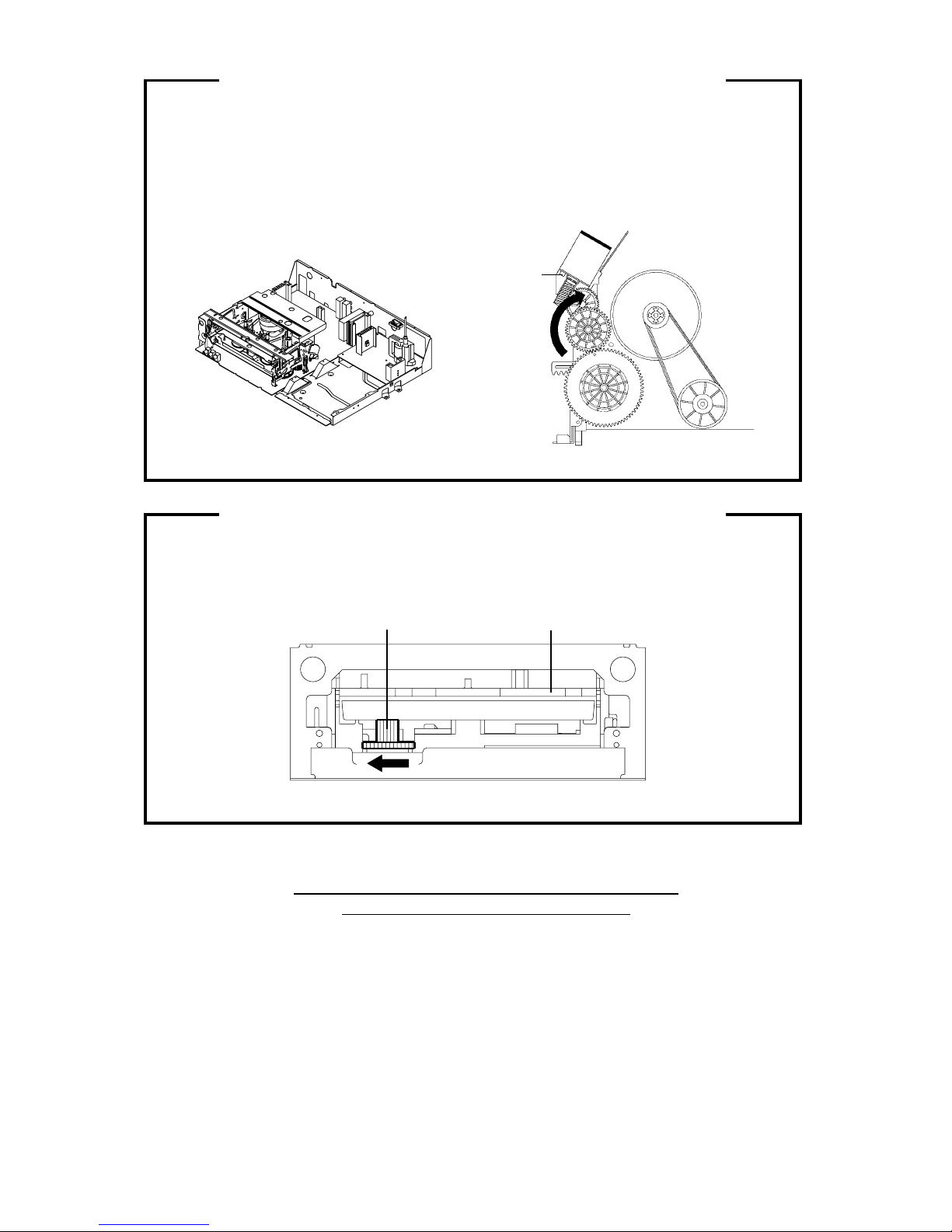
TAPE REMOVAL METHOD AT NO POWER SUPPLY .........................................................
DISC REMOVAL METHOD AT NO POWER SUPPLY ..........................................................
PARENTAL CONTROL-RATING LEVEL ...............................................................................
TABLE OF CONTENTS...........................................................................................................
GENERAL SPECIFICATIONS.................................................................................................
DISASSEMBLY INSTRUCTIONS
1. REMOVAL OF MECHANICAL PARTS AND P. C. BOARDS.........................................
2. REMOVAL OF VCR DECK PARTS ................................................................................
3. REMOVAL OF DVD DECK PARTS ................................................................................
4. REMOVAL OF ANODE CAP...........................................................................................
5. REMOVAL AND INSTALLATION OF FLAT PACKAGE IC ............................................
KEY TO ABBREVIATIONS .....................................................................................................
SERVICE MODE LIST .............................................................................................................
PREVENTIVE CHECKS AND SERVICE INTERVALS...........................................................
WHEN REPLACING EEPROM (MEMORY) IC ......................................................................
SERVICING FIXTURES AND TOOLS ....................................................................................
PREPARATION FOR SERVICING..........................................................................................
MECHANICAL ADJUSTMENTS .............................................................................................
ELECTRICAL ADJUSTMENTS...............................................................................................
BLOCK DIAGRAMS
DVD.......................................................................................................................................
Y/C/AUDIO/HEAD AMP .......................................................................................................
MICON..................................................................................................................................
IN/OUT..................................................................................................................................
CHROMA/IF..........................................................................................................................
SOUND AMP/SURROUND..................................................................................................
Hi-Fi/DEMODULATOR.........................................................................................................
DIGITAL COMB FILTER ......................................................................................................
DVD IN/OUT.........................................................................................................................
REGULATOR .......................................................................................................................
TV .........................................................................................................................................
PRINTED CIRCUIT BOARDS
DVD.......................................................................................................................................
VCR.......................................................................................................................................
DEFLECTION/CRT/OPERATION ........................................................................................
SCHEMATIC DIAGRAMS
MPEG/MICON/DSP..............................................................................................................
MEMORY ..............................................................................................................................
MOTOR DRIVE ....................................................................................................................
AUDIO/VIDEO ......................................................................................................................
Y/C/AUDIO/HEAD AMP .......................................................................................................
MICON ..................................................................................................................................
IN/OUT ..................................................................................................................................
CHROMA/IF..........................................................................................................................
SOUND AMP/SURROUND ..................................................................................................
Hi-Fi/DEMODULATOR .........................................................................................................
DIGITAL COMB FILTER ......................................................................................................
DVD IN/OUT .........................................................................................................................
REGULATOR........................................................................................................................
TV POWER ..........................................................................................................................
DEFLECTION .......................................................................................................................
CRT/OPERATION ................................................................................................................
INTERCONNECTION DIAGRAM ............................................................................................
WAVEFORMS ..........................................................................................................................
MECHANICAL EXPLODED VIEWS........................................................................................
CHASSIS EXPLODED VIEWS ................................................................................................
DVD DECK EXPLODED VIEWS .............................................................................................
MECHANICAL REPLACEMENT PARTS LIST ......................................................................
CHASSIS REPLACEMENT PARTS LIST...............................................................................
DVD DECK REPLACEMENT PARTS LIST............................................................................
ELECTRICAL REPLACEMENT PARTS LIST........................................................................
A1-1
A1-1
A1-2
A1-2
A1-3
A1-3
A1-3
A2-1
A3-1~A3-6
B1-1~B1-3
B2-1~B2-6
B3-1~B3-3
B4-1
B5-1, B5-2
C1-1, C1-2
C2-1
C3-1, C3-2
C4-1
D1-1
D1-1
D2-1~D2-4
D3-1~D3-6
E-1, E-2
E-3, E-4
E-5, E-6
E-7, E-8
E-9, E-10
E-11, E-12
E-13, E-14
E-15, E-16
E-17, E-18
E-19, E-20
E-21, E-22
F-1, F-2
F-3~F-6
F-7, F-8
G-1, G-2
G-3, G-4
G-5, G-6
G-7, G-8
G-9, G-10
G-11, G-12
G-13, G-14
G-15, G-16
G-17, G-18
G-19, G-20
G-21, G-22
G-23, G-24
G-25, G-26
G-27, G-28
G-29, G-30
G-31, G-32
G-33, G-34
H-1~H-3
I1-1, I1-2
I2-1, I2-2
I3-1
J1-1
J2-1
J3-1
J4-1~J4-3
A2-1

GENERAL SPECIFICATIONS
G-1 TV CRT CRT Size / Visual Size 20 inch / 508.0mmV
System CRT Type Flat
Magnetic Field BV/BH +0.45G / 0.18G
Color System NTSC
Speaker 2 Speaker
Position Front
Size 1.8 x 3.9 Inch
Impedance 8 ohm
Sound Output MAX 1.5W + 1.5W
10%(Typical) __
G-2 VCR System VHS Player / Recorder
System Video System NTSC
Hi-Fi STEREO Yes
NTSC PB -
Deck OVD-7
Heads Video Head 4 Heads
FM Audio Head 2 Heads
Audio /Control Mono /Yes
Erase(Full Track Erase) Yes
Tape Rec PAL -
Speed NTSC SP/SLP
Play PAL -
NTSC SP/LP/SLP
Fast Forward / Rewind Time (Approx.) at 25oC FF:1'48"/REW:1'48"
with Cassette T-120
Forward/Reverse NTSC or PAL-M SP/LP/SLP=3x,5x/7x,9x/9x,15x
Picture Search
Frame Advance Yes
Slow Speed 1/10
G-3 DVD System Color System NTSC
Disc DVD, CD-DA, CD-R/RW
DVD-R/RW (Video Format Only)
Disc Diameter 120 mm , 80 mm
Drive DM3PA
Search speed Fwd 4 step
Actual 2-45 times(DVD)
4-40 times (CD)
Rev 4 step
Actual 2-45 times(DVD)
4-40 times (CD)
Slow speed Fwd 1/7 - 1/2 times
Actual --
Rev --
Actual --
G-4 Tuning Broadcasting System US System M
System Tuner and System 1 Tuner
Receive CH Destination US(w/CABLE)
CH Coverage 2~69, 4A, A-5~A-1, A~I, J~W, W+1~W+84
Intermediate Picture(FP) 45.75MHz
Frequency Sound(FS) 41.25MHz
FP-FS 4.5MHz
Preset CH No
Stereo/Dual TV Sound US-Stereo
Tuner Sound Muting Yes
G-5 Signal Video Signal Input Level 1 V p-p/75 ohm
Output Level 1 V p-p/75 ohm
S/N Ratio (Weighted) at DVD Mode 65dB
S/N Ratio (Weighted) at VCR Mode 50dB
Horizontal Resolution at DVD Mode 400 Lines
Horizontal Resolution at VCR(SP)Mode 220 Lines
RGB Signal Output Level -
Audio Signal Input Level -8.0dBm/50k ohm
VCR Output Level(0dB=0.775Vrms) -8.0dBm/1k ohm
DVD Output Level(-20dBFs 0dBFs=2.0Vrms) -12.0dBm/1k ohm
Digital Output Level 0.5 V p-p/75 ohm(DVD)
S/N Ratio at DVD (Weighted) 90 dB
S/N Ratio at VCR (SP)(CCIR Filter:ON) 38 dB
Harmonic Distortion at DVD Mode 0.06% (1kHz)
Harmonic Distortion at VCR(SP) Mode 1.5% (1kHz) Typical
Frequency Response :
DVD Mode at DVD 4Hz - 22kHz
at Video CD -
at SVCD -
at CD 4Hz - 20kHz
VCR Mode at SP 100Hz - 10kHz
A3-1

GENERAL SPECIFICATIONS
at LP 100Hz - 6kHz
at SLP 100Hz - 4kHz
Hi-Fi Audio Signal Dynamic Range : More than 90 dB
Frequency Response : 20Hz - 20kHz
Wow And Flutter : Less than 0.01 %Wrms
Channel Separation : More than 60 dB
Harmonic Distortion : Less than 1.0 %
G-6 Power Power Source AC 120V,60Hz
DC -
Power Consumption at AC 110 W at 120 V 60 Hz
at DC -
Stand by (at AC) 4 W at 120 V 60 Hz
Per Year -
Protector Power Fuse Yes
Safety Circuit Yes
IC Protector(Micro Fuse) No
Dew Sensor No
G-7 Regulation Safety UL
Radiation FCC
X-Radiation DHHS
Laser DHHS
G-8 Temperature Operation +
5
o
C
~ +4
0
o
C
Storage -2
0
o
C
~ +
60
o
C
G-9 Operating Humidity Less than 80% RH
G-10 On Screen Menu Yes
Display Menu Type Icon
(TV/VCR) System Setup Yes
Clock Set Yes
On/Off Timer Set Yes
Auto Clock On/Off Yes
Standard Time Yes
Daylight Saving Time Yes
TV Setup Yes
Language Yes
Picture Yes
Audio Yes
Picture Preference Yes
Channel Setup Yes
TV/CABLE Yes
Auto CH Memory Yes
Add/ Delete Yes
V-chip Setup Yes
Tape Setup Yes
Timer Rec Set Yes
Auto Repeat On/Off Yes
G-CODE(or SHOWVIEW or PLUSCODE)No. Entry No
Clock / Date Yes
TV/VCR Yes
DVD Yes
CH/AV(LINE) Yes
Tape Counter(Linear Counter) Yes
Tape Speed Yes
Sleep Time Yes
Stereo/Audio Output Yes
Bilingual No
SAP Yes
Control Volume Yes
Level Brightness/Contrast/Sharpness/Color Yes
Tint Yes
Bass/Treble/Balance Yes
Manual Tracking Yes
Play/Stop/FF/Rew/Rec/OTR/T-Rec/Pause/Eject/Tape In (Symbol
Mark
)
Yes
Auto Tracking/Manual Tracking Yes
Caption / Text Yes
Index Yes
Mute Yes
Hi-Fi Yes
Repeat Yes
Zero Return Yes
DEW No
G-11 On Screen Menu (DVD) Yes
Display Menu Type Icon
(DVD) Language Yes
Menu Yes
Subtitle Yes
Audio Yes
OSD Language(Set up Language) No
A3-2

GENERAL SPECIFICATIONS
Video Yes
E.B.L. (Enhanced Black Level) No
TV Screen Size(4:3) Yes
OSD Display On/Off Yes
Picture Mode (Video/Film/Auto) Yes
JPEG Interval Yes
Audio Yes
DRC (Dynamic Range Control) Yes
Dialogue (On DRC[TV] / Off DRC[Std]) No
Surround No
System Yes
Disc/Card Slot No
Password Lock/ Un Lock Yes
Parental Yes
Select Files Yes
HDMI (480p/1080i/720p) No
Output No
Open Yes
Close Yes
No Disc Yes
Reading Disc Yes
Play Yes
Still/Pause Yes
Stop Yes
Prohibit Mark Yes
PBC No
Step Yes
Skip(>>|) Yes
Skip(|<<) Yes
Random Yes (CD,MP3,WMA,JPEG)
Repeat Yes
Slow+ Yes
Slow- No
Search+ Yes
Search- Yes
Jump Yes
Resume Yes
Title No. Yes
Chapter No. Yes
Track No. Yes
Time Yes
Sub Title No. Yes
Angle No. Yes
Vocal On/Off No
Audio No. Yes
Audio Stereo L/R No
Zoom Yes
Marker No. No
Program Play Back Yes (CD, MP3, WMA, JPEG)
Surround On/Off No
Screen Saver No
MP3, WMA, JPEG Folder Name Yes
File Name Yes
File No Yes
Time Yes (MP3,WMA Only)
Track No Yes
G-12 OSD Language English French Spanish
G-13 Clock,Timer Calendar 1990/1/1 ~ 2081/12/31
and Timer Timer Events 8 Program/ 1 Month
Back-up One Touch Recording Max Time 6 Hours
Sleep Timer Max Time 120 Min
Step 10 Min
On/Off Timer Program(On Timer / Off Timer) 1 Program
Auto Shut Off No Signal 15 Min
No Operation - Min
Timer Back-up (at Power Off Mode) 5 Sec
G-14 Remote Unit RC-HH
Control Glow in Dark Remocon No
Unit Remocon Format ORION
Format NEC
Custom Code 71-8E
Power Source Voltage(D.C) 3V
UM size x pcs UM-4 x 2 pcs
Total Keys 52
Keys TV/VCR Yes
DVD Yes
Power Yes
A3-3

GENERAL SPECIFICATIONS
1Yes
2Yes
3Yes
4Yes
5Yes
6Yes
7Yes
8Yes
9Yes
0Yes
Channel- Yes
Channel+ Yes
Volume- Yes
Volume+ Yes
Display (Call) Yes
Sleep Yes
Audio Select Yes
Mute Yes
Index- / Skip- Yes
Index+ / Skip+ Yes
T-REC Yes
Rec/OTR Yes
Slow+ Yes
Play Yes
Stop Yes
Rew / Search- Yes
F. Fwd / Search+ Yes
Pause / Still Yes
CM Skip Yes
Speed / Return Yes
Counter Reset / Angle Yes
Zero Return / Subtitle Yes
Input Select / Zoom Yes
Menu /Set Up Yes
Program / Repeat A-B Yes
ATR / Top Menu Yes
Tracking+ / DVD Menu Yes
Tracking- / Play Mode Yes
Cancel Yes
3D Surround No
Cursor Up Yes
Cursor Down Yes
Cursor Left Yes
Cursor Right Yes
Enter Yes
Eject Yes
Open/Close Yes
TV Monitor Yes
Closed Caption Yes
Quick View / Jump Yes
CABLE No
WIDE No
Position No
G-15 Features Auto Head Cleaning Yes
(TV/VCR) VIDEO PLUS+(SHOWVIEW,G-CODE) No
Auto Clock Yes
Picture Preference Yes
Auto Setup No
Forward / Reverse Picture Search Yes
Auto CH Memory Yes
Surround Yes
Stable Sound Yes
Closed Caption Yes
TV Auto Shut off Function Yes
End Call No
Index Search Yes
SQPB No
CABLE Yes
CM Skip(30sec x 6 Times) Yes
Comb Filter (2Lines) Yes
VM Circuit No
TV Monitor Yes
Program Extend No
Choke Coil No
Energy Star No
Protect of FBT Leak Circuit Yes
Zero Return Yes
A3-4

GENERAL SPECIFICATIONS
Power On Memory No
V-chip USA V-chip Yes
CANADA V-chip No
Features Tray Lock No
(DVD) Auto Stop (Pause, and Resume Stop after 5min.) Yes
Card Slot Reading (Not secured Data) No
xD-Picture Card No
Memory Stick No
Multi Media Card No
SD Memory Card No
Compact Flash No
Micro Drive No
SmartMedia No
Video CD Playback No
SVCD Playback No
MP3 Playback Yes
WMA Playback Yes
JPEG Playback Yes
Digital Out (Dolby Digital) Yes
(MPEG) Yes
(PCM) Yes
(DTS) Yes
Down Mix Out (Dolby Digital) Yes
(DTS) No
3D Surround No
Screen Saver No
Audio DAC 192kHz / 24bit
Copy (Disc to Tape) No
G-16 Accessories Owner's Manual Language English / Spanish
w/Guarantee Card No
Remote Control Unit Yes
Battery No
UM size x pcs -
OEM Brand -
Rod Antenna No
Poles -
Terminal -
Loop Antenna No
Terminal -
U/V Mixer No
300 ohm to 75 ohm Antenna Adapter No
Antenna Change Plug No
DC Car Cord (Center+) No
AC Plug Adapter No
AC Cord No
AV Cord (2Pin-1Pin) No
Guarantee Card Yes
Registration Card No
ESP Card No
Warning Sheet No
Dew/AHC Caution Sheet No
Quick Set-up Sheet No
Circuit Diagram No
Service Facility List No
Important Safeguard No
Sheet Information (Return) No
G-17 Interface Switch Front Power (Tact) Yes
Channel Up Yes
Channel Down Yes
Volume Up Yes
Volume Down Yes
Play (VCR) Yes
Stop / Eject (VCR) Yes
F.FWD/Cue (VCR) Yes
Rew/Rev (VCR) Yes
REC/OTR (VCR) Yes
Play (DVD) Yes
Stop (DVD) Yes
Skip+ /Search+ (DVD) Yes
Skip- /Search- (DVD) Yes
Open/Close (DVD) Yes
Input Select No
Main Power SW No
Indicator Power Yes(Red)
REC/OTR Yes(Red)
T-REC Yes(Red)
TV/VCR No
A3-5

GENERAL SPECIFICATIONS
DVD No
Terminals Front Video Input RCA x 1
Audio Input RCA x 2(Stereo)
4 in 1 Card Slot No
Compact Flash Card Slot No
Other Terminal HeadPhone (Stereo & Mono, 3.5mm)
Rear Video Input RCA x 1
Audio Input RCA x 2(Stereo)
Video Output RCA x1
Audio Output RCA x 2(Stereo)
Digital Audio Output Coaxial (DVD Only)
VHF/UHF Antenna Input F Type
AC Inlet No
G-18 Set Size Approx. W x D x H (mm) 573 x 485 x 517
G-19 Weight Net (Approx.) 27.0kg (59.5lbs)
Gross (Approx.) 30.5kg (67.3lbs)
G-20 Carton Master Carton No
Content -
Material -
Dimensions W x D x H(mm) -
Description of Origin -
Gift Box Material Double/Brown
Dimensions W x D x H(mm) 658 x 575 x 625
Description of Origin Yes
Drop Test Natural Dropping At 1 Corner / 3 Edges / 6 Surfaces
Height (cm) 31
Container Stuffing(40' container) 216 Sets
G-21 Material Cabinet Front PS 94V0 DECABROM
Rear PS 94V0 DECABROM
Jack Panel -
PCB Non-Halogen Demand No
Eyelet Demand Yes
G-22 Environment Environmental standard requirement (by buyer) No
Pb-free No
A3-6

DISASSEMBLY INSTRUCTIONS
B1-1
1. REMOVAL OF MECHANICAL PARTS
AND P.C. BOARDS
1-1: BACK CABINET (Refer to Fig. 1-1)
1.
2.
3.
Remove the 6 screws (1).
Remove the 2 screws (2).
Remove the Back Cabinet in the direction of arrow.
1-2: CRT PCB (Refer to Fig. 1-2)
CAUTION: BEFORE REMOVING THE ANODE CAP,
DISCHARGE ELECTRICITY BECAUSE IT
CONTAINS HIGH VOLTAGE.
BEFORE ATTEMPTING TO REMOVE OR
REPAIR ANY PCB, UNPLUG THE POWER
CORD FROM THE AC SOURCE.
1.
2.
3.
Remove the Anode Cap.
(Refer to REMOVAL OF ANODE CAP)
Disconnect the following connectors:
(CP603B, CP803 and CP805).
Remove the CRT PCB in the direction of arrow.
Fig. 1-1
Front Cabinet
(1)
(1)
(1)
(1) Back Cabinet
(1)
(1)
(2)
(2)
CRT PCB
Front Cabinet
Fig. 1-2
1-3: TV/DVD/VCR BLOCK (Refer to Fig. 1-3)
1.
2.
3.
Remove the 2 screws (1).
Disconnect the following connectors:
(CP303, CP404 and CP1704).
Remove the TV/DVD/VCR Block in the direction of
arrow.
Fig. 1-3
TV/DVD/VCR Block
(1)
(1)
Front Cabinet
1-4: VCR DECK (Refer to Fig. 1-4)
NOTE
Do not remove the cable at the FE Head section. The FE
Head may be damaged if you remove the cable by force.
1.
2.
3.
4.
5.
6.
7.
8.
9.
10.
Remove the 2 screws (1).
Remove the VCR Top.
Move the Cassette Holder Ass'y to the back side.
Remove the 3 screws (2).
Remove the 2 screws (3).
Remove the Deck Shield Cover.
Remove the screw (4).
Remove the FE Head.
Disconnect the following connectors:
(CP101, CP4501 and CP4502).
Remove the VCR Deck in the direction of arrow.
Fig. 1-4
(1)
(1) VCR Top
(2)
(2)
(2)
(3)
(3)
Deck Shield Cover (4)
FE Head
VCR Deck
Bottom Plate

DISASSEMBLY INSTRUCTIONS
B1-2
1-5:VCR PCB (Refer to Fig. 1-5)
1.
2.
3.
4.
5.
Remove the 6 screws (1).
Remove the screw (2).
Remove the AV Jack Shield.
Disconnect the following connectors:
(CP001, CP602B, CP604, CP2201, CP8001 and CP8002).
Remove the VCR PCB in the direction of arrow.
Fig. 1-5
(1)
(1) (1)
(1)(1)(1)(2)
VCR PCB
Bottom Plate
AV Jack Shield
1-6:VCR DECK (Refer to Fig. 1-6)
1.
2.
3.
4.
Remove the 4 screws (1).
Remove the DVD Block in the direction of arrow (A).
Remove the 2 screws (2).
Remove the Operation PCB in the direction of arrow (B).
Fig. 1-6
DVD Block
(1) (1)
(1)
(1)
(A)
(2)
(B)
Operation PCB
Bottom Plate
(2)
1-7: DVD PCB/DVD DECK (Refer to Fig. 1-7)
1.
2.
3.
4.
5.
6.
7.
8.
Short circuit the position shown in Fig. 1-7 using
a soldering iron. If you remove the DVD Deck
with no soldering, the Laser may be damaged.
Remove the 4 screws (1).
Remove the DVD Top in the direction of arrow (A).
Remove the 2 screws (2).
Remove the DVD PCB in the direction of arrow (B).
Disconnect the following connectors:
(CP2301, CP2302 and CP2303).
Remove the 4 screws (3).
Remove the DVD Deck in the direction of arrow (C).
Fig. 1-7
Pick Up PCB
Short circuit using a
soldering iron.
(1)
(A) (2)
(1)
DVD Top
(3)
(2)
DVD Deck
(3) (3)
(3)
(B)
(C)
(1)
(1)
Angle Deck
NOTE
Before your operation, please read “PREPARATION OF
SERVICING”.
Use the Lead Free solder.
Manual soldering conditions
• Soldering temperature: 320 ±20˚C
• Soldering time: Within 3 seconds
• Soldering combination: Sn-3.0Ag-0.5Cu
When Soldering/Removing of solder, use the drawing
equipment over the Pick Up Unit to keep the Flux smoke
away from it.
When installing the DVD Deck, remove all the soldering
on the short circuit position after the connection of Pick Up
PCB and DVD PCB connector.
1.
2.
3.
4.
5.

DISASSEMBLY INSTRUCTIONS
1-8: DEFLECTION PCB (Refer to Fig. 1-8)
1.
2.
3.
Remove the 2 screws (1).
Remove the 3 screws (2).
Remove the Deflection PCB in the direction of arrow.
Fig. 1-8
Deflection PCB
(1)(1)
Bottom Plate
(2)
(2) (2)
B1-3

DISASSEMBLY INSTRUCTIONS
B2-1
2. REMOVAL OF VCR DECK PARTS
2-1: TOP BRACKET (Refer to Fig. 2-1)
Extend the 2 supports 1.
Slide the 2 supports 2and remove the Top Bracket.
1.
2.
2-2: CASSETTE HOLDER ASS'Y (Refer to Fig. 2-2)
Move the Cassette Holder Ass'y to the front side.
Push the Locker R to remove the Cassette Side R.
Remove the Cassette Side L.
1.
2.
3.
Fig. 2-1
2
2
Main Chassis
Main Chassis
Top Bracket
Top Bracket
Main Chassis
Main Chassis
Cassette Side L
Cassette Side R Locker R
Fig. 2-2
Link Unit
2-3: LINK UNIT (Refer to Fig. 2-3)
Set the Link Unit to the Eject position.
Unlock the support 1.
Remove the (A) side of the Link Unit first, then remove
the (B) side.
1.
2.
3.
Fig. 2-3
(A)
Link Unit
Main Chassis
1
Link Unit
(B)
Main Chassis
11
NOTE
1. After installation of the Top Bracket, bend the support
1so that the Top Bracket is fixed.
2-4: LINK LEVER/FLAP LEVER (Refer to Fig. 2-4)
Extend the support 1.
Remove the Link Lever.
Remove the Flap Lever.
1.
2.
3.
Fig. 2-4
Link Lever
Flap Lever
1
2-5: LOADING MOTOR/WORM (Refer to Fig. 2-5-A)
Remove the screw 1.
Remove the Loading Motor.
Remove the Worm.
1.
2.
3.
Fig. 2-5-A
• Screw Torque: 3 ±0.5kgf•cm
Loading Motor
1
Main Chassis
Worm
NOTE
1.
2.
3.
In case of the Worm installation, check if the value of
the Fig. 2-5-B is correct.
In case of the Loading Motor installation, hook the wire
on the Cassette Opener as shown Fig. 2-5-C.
When installing the wires between Capstan DD Unit
and Loading Motor, connect them correctly as shown
Fig. 2-5-D.
Fig. 2-5-B
19.2 ±0.1mm
Safety surface for pressing
of the insert.

DISASSEMBLY INSTRUCTIONS
B2-2
2-6: TENSION ASS'Y (Refer to Fig. 2-6-B)
Turn the Pinch Roller Cam clockwise so that the
Tension Holder hook is set to the position of Fig. 2-6-A
to move the Tension Arm Ass'y.
Remove the Tension Spring.
Unlock the 2 supports 1and remove the Tension
Band.
Unlock the support 2and remove the Tension Arm
Ass'y.
Unlock the support 3and remove the Tension
Connect.
Float the hook 4and turn it clockwise then remove the
Tension Holder.
1.
2.
3.
4.
5.
6.
Fig. 2-6-A
Tension Arm Ass'y
Fig. 2-6-B
Fig. 2-6-D
Tension Band
Tension Spring
1
2
4
Tension Band
Tension Arm Ass'y
3
1
Tension Holder
Tension Connect
NOTE
1.
2.
3.
In case of the Tension Band installation, note the
direction of the installation. (Refer to Fig. 2-6-C)
In case of the Tension Band installation, install correctly
as Fig. 2-6-D.
In case of the Tension Connect installation, install as
the circled section of Fig. 2-6-E.
Tension Band
Tension Connect
Tension Connect
[OK]
[NG]
Fig. 2-6-E
Tension Connect
Main Chassis
Fig. 2-6-C
Tension Band
Tension Connect
Loading Motor Capstan DD Unit
-
+
L2
L1
Pink
Fig. 2-5-D
White
2-7: T BRAKE ARM/T BRAKE BAND (Refer to Fig. 2-7-A)
Remove the T Brake Spring.
Turn the T Brake Arm clockwise and bend the hook
section to remove it.
Unlock the 2 supports 1and remove the T Brake
Band.
1.
2.
3.
T Brake Band
Hook section
T Brake Spring
T Brake Arm
1
1
Fig. 2-7-A
Fig. 2-5-C
Loading Motor
Slacken the wire.

DISASSEMBLY INSTRUCTIONS
B2-3
Fig. 2-8-B
Big Hole
(S Reel) Small Hole
(T Reel)
Fig. 2-8-C
Idler Arm Ass'y
[OK]
[NG]
Clutch Gear
Idler Arm Ass'y
Clutch Gear
Fig. 2-7-B
T Brake Band
NOTE
1. In case of the T Brake Band installation, install correctly
as Fig. 2-7-B.
T Brake Arm
[OK]
[NG] T Brake Band
T Brake Arm
2-8: S REEL/T REEL/IDLER ARM ASS'Y/IDLER GEAR
(Refer to Fig. 2-8-A)
Remove the S Reel and T Reel.
Remove the 2 Polyslider Washers 1.
Remove the Idler Arm Ass'y and Idler Gear.
1.
2.
3.
NOTE
Take care not to damage the gears of the S Reel and T
Reel.
The Polyslider Washer may remain on the back of the
reel.
Take care not to damage the shaft.
Do not touch section "A" of S Reel and T Reel. (Use
gloves.) (Refer to Fig. 2-8-A) Touching may leave stains
on section "A"
When you install the reel, clean the shaft and grease it
(FG-84M) . (If you do not grease, noise may be heard in
FF/REW mode.)
After installing the reel, adjust the height of the reel.
(Refer to MECHANICAL ADJUSTMENT)
1.
2.
3.
4.
5.
6.
NOTE
1.
2.
In case of the S Reel and T Reel installation, check if the
correct parts are installed. (Refer to Fig. 2-8-B)
In case of the Idler Arm Ass'y installation, install correctly
as Fig. 2-8-C. And also set it so that the section "B" of
Fig. 2-8-A is placed under the Main Chassis tab.
2-9: CASSETTE OPENER/PINCH ROLLER BLOCK/
P5 ARM ASS'Y (Refer to Fig. 2-9-A)
Unlock the support 1and remove the Cassette
Opener.
Remove the Pinch Roller Block and P5 Arm Ass'y.
1.
2.
Fig. 2-9-A
1Cassette Opener
P5 Arm Ass'y
Pinch Roller Block
Main Chassis
NOTE
Do not touch the Pinch Roller. (Use gloves.)
In case of the Pinch Roller Block and the Pinch Roller
Cam installation, install correctly as Fig. 2-9-B.
1.
2.
Fig. 2-9-B
Can be seen the hole of the
Main Cam.
Can be seen the hole of
the Pinch Roller Cam.
P5 Arm Ass'y
Pinch Roller Block
Fig. 2-8-A
S Reel
1
(A) T Reel
(A)
1
Idler Arm Ass'y
Idler Gear
(B)

DISASSEMBLY INSTRUCTIONS
B2-4
A/C Head
2
2
A/C Head Spring
1
(3)
(1)
2
(2)
A/C Head Base
Spring Position Fig. 2-10-B
2-11: FE HEAD (RECORDER ONLY) (Refer to Fig. 2-11)
Remove the screw 1.
Remove the FE Head.
1.
2.
FE Head
• Screw Torque: 5 ±0.5kgf•cm
• The FE Head is not installed on the Video Cassette Player.
Fig. 2-10-A
• Screw Torque: 5 ±0.5kgf•cm
Fig. 2-11
1
2-10: A/C HEAD (Refer to Fig. 2-10-A)
Remove the screw 1.
Remove the A/C Head Base.
Remove the 3 screws 2.
Remove the A/C Head and A/C Head Spring.
1.
2.
3.
4.
NOTE
Do not touch the A/C Head. (Use gloves.)
When you install the A/C Head Spring, install as shown in
Fig. 2-10-B.
When you install the A/C Head, tighten the screw (1) first,
then tighten the screw (2), finally tighten the screw (3).
1.
2.
3.
2-12: AHC ASS'Y/CYLINDER UNIT ASS'Y
(Refer to Fig. 2-12)
Unlock the support 1and remove the AHC Ass'y.
Disconnect the following connector:
(CD2001)
Remove the 3 screws 2.
Remove the Cylinder Unit Ass'y.
1.
2.
3.
4.
When you install the Cylinder Unit Ass'y, tighten the
screws from (1) to (3) in order while pulling the Ass'y
toward the left front direction.
NOTE
Fig. 2-12
1.
Cylinder Unit Ass'y
2
2
2
• Screw Torque: 3 ±0.5kgf•cm
(1)
(3)
(2)
AHC Ass'y
1
2-13: CAPSTAN DD UNIT (Refer to Fig. 2-13)
Remove the Capstan Belt.
Remove the screw 1.
Remove the Capstan Holder.
Remove the 3 screws 2.
Remove the Capstan DD Unit.
1.
2.
3.
4.
5.
• Screw Torque: 4 ±0.5kgf•cm
Capstan DD Unit
Capstan Belt
Fig. 2-13
1
2
Capstan Holder
2
2

DISASSEMBLY INSTRUCTIONS
B2-5
Fig. 2-14-A
NOTE
In case of the Pinch Roller Cam and Main Cam
installation, install them as shown in the circled section
of Fig. 2-15-B so that the markers meet. (Refer to Fig.
2-14-B)
And also can be seen the Main Chassis hole through the
Main Cam maker hole.
2-14:
Remove the E-Ring 1, then remove the Main Cam.
Remove the E-Ring 2, then remove the Pinch Roller
Cam and Joint Gear.
1.
2.
MAIN CAM/PINCH ROLLER CAM/JOINT GEAR
(Refer to Fig. 2-14-A)
1
Main Cam
Pinch Roller Cam
Joint Gear
2
1.
NOTE
1. When you install the Loading Arm S Unit, Loading Arm
T Unit and Main Loading Gear, align each marker.
(Refer to Fig. 2-15-B)
Fig. 2-15-B
Loading Arm T Unit
Main Loading Gear
Marker
Marker
Loading Arm S Unit
2-16:
Remove the Polyslider Washer 1.
Remove the Clutch Ass'y and Ring Spring.
Remove the Clutch Lever.
Remove the Coupling Gear, Coupling Spring and
Clutch Gear.
1.
2.
3.
4.
Fig. 2-16-A
1
Clutch Ass'y
Coupling Gear Clutch Lever
Ring Spring
Coupling Spring
Clutch Gear
CLUTCH ASS'Y/RING SPRING/CLUTCH LEVER/
CLUTCH GEAR (Refer to Fig. 2-16-A)
2-15: LOADING GEAR S/T UNIT (Refer to Fig. 2-15-A)
1.
2.
Remove the E-Ring 1and remove the Main Loading
Gear.
Remove the Main Rod, Tension Lever, Loading Arm S
Unit and Loading Arm T Unit.
1
Main Rod Main Loading Gear
Tension Lever
Loading Arm T Unit
Loading Arm S Unit
Fig. 2-15-A
Fig. 2-14-B
Pinch Roller Cam
Main Cam
Marker

DISASSEMBLY INSTRUCTIONS
B2-6
2-17:
Remove the P4 Cap.
Unlock the support 1and remove the Cassette Guide
Post.
Remove the Inclined Base S/T Unit.
Remove the screw 2.
Remove the LED Reflector.
1.
2.
3.
4.
5.
Fig. 2-17-A
CASSETTE GUIDE POST/INCLINED BASE S/T
UNIT/P4 CAP/LED REFLECTOR
(Refer to Fig. 2-17-A)
P4 Cap
Cassette Guide Post
1
Inclined Base T
Unit
Inclined Base S
Unit
NOTE
Do not touch the roller of Guide Roller.
In case of the P4 Cap installation, install it with parallel
for "A" and "B" of Fig. 2-17-B.
In case of the Cassette Guide Post installation, install
correctly as the circled section of Fig. 2-17-C.
1.
2.
3.
"A"
[OK]
[NG]
"B"
P4 Cap Cassette Opener
Fig. 2-17-B
Fig. 2-17-C
Cassette Guide Post
Cassette Guide Post
NOTE
In case of the Clutch Ass'y installation, install it with
inserting the spring of the Clutch Ass'y into the dent of
the Coupling Gear. (Refer to Fig. 2-16-B)
1.
Clutch Ass'y
Fig. 2-16-B
Coupling Gear
2
LED Reflector
• Screw Torque: 5 ±0.5kgf•cm
This manual suits for next models
1
Table of contents
Other Memorex TV DVD Combo manuals

Memorex
Memorex MVUC821 - DVD LCD TV Kitchen Clock Radio User manual

Memorex
Memorex MVD2009CB User manual

Memorex
Memorex MVD2113 User manual

Memorex
Memorex MVD1402 User manual

Memorex
Memorex MVDT2402 User manual

Memorex
Memorex MLTD2622 - 26" LCD TV User manual

Memorex
Memorex MVD2009CB User manual

Memorex
Memorex MVDT2002A User manual

Memorex
Memorex MVD-2256 User manual

Memorex
Memorex MVD2019 User manual