ProSoft MVI56E-AFC User manual

MVI56E-AFC
Enhanced Liquid and Gas Flow
Computer for ControlLogix®
v4.04
October 2, 2018
SETUP AND CONFIGURATION GUIDE

Your Feedback Please
We always want you to feel that you made the right decision to use our products. If you have suggestions, comments,
compliments or complaints about our products, documentation, or support, please write or call us.
ProSoft Technology, Inc.
+1 (661) 716-5100
+1 (661) 716-5101 (Fax)
www.prosoft-technology.com
© 2018 ProSoft Technology, Inc. All rights reserved.
October 2, 2018
ProSoft Technology®, is a registered copyright of ProSoft Technology, Inc. All other brand or product names are or
may be trademarks of, and are used to identify products and services of, their respective owners.
In an effort to conserve paper, ProSoft Technology no longer includes printed manuals with our product shipments.
User Manuals, Datasheets, Sample Ladder Files, and Configuration Files are available at:
www.prosoft-technology.com
For professional users in the European Union
If you wish to discard electrical and electronic equipment (EEE), please contact your dealer or supplier
for further information.
Warning –Cancer and Reproductive Harm –www.P65Warnings.ca.gov
Important Installation Instructions
Power, Input, and Output (I/O) wiring must be in accordance with Class I, Division 2 wiring methods, Article 501 to 4
(b) of the National Electrical Code, NFPA 70 for installation in the U.S., or as specified in Section 18-1J2 of the
Canadian Electrical Code for installations in Canada, and in accordance with the authority having jurisdiction. The
following warnings must be heeded:
WARNING - EXPLOSION HAZARD - SUBSTITUTION OF COMPONENTS MAY IMPAIR SUITABILITY FOR CLASS
I, DIV. 2.
WARNING - EXPLOSION HAZARD - WHEN IN HAZARDOUS LOCATIONS, TURN OFF POWER BEFORE
REPLACING OR WIRING MODULES.
WARNING - EXPLOSION HAZARD - DO NOT DISCONNECT EQUIPMENT UNLESS POWER HAS BEEN
SWITCHED OFF OR THE AREA IS KNOWN TO BE NON-HAZARDOUS.
Class 2
MVI (Multi Vendor Interface) Modules
WARNING - EXPLOSION HAZARD - DO NOT DISCONNECT EQUIPMENT UNLESS POWER HAS BEEN
SWITCHED OFF OR THE AREA IS KNOWN TO BE NON-HAZARDOUS.
AVERTISSEMENT - RISQUE D'EXPLOSION - AVANT DE DÉCONNECTER L'ÉQUIPEMENT, COUPER LE
COURANT OU S'ASSURER QUE L'EMPLACEMENT EST DÉSIGNÉ NON DANGEREUX.

Warnings
North America Warnings
Power, Input, and Output (I/O) wiring must be in accordance with Class I, Division 2 wiring methods, Article 501 to 4
(b) of the National Electrical Code, NFPA 70 for installation in the U.S., or as specified in Section 18-1J2 of the
Canadian Electrical Code for installations in Canada, and in accordance with the authority having jurisdiction. The
following warnings must be heeded:
A Warning - Explosion Hazard - Substitution of components may impair suitability for Class I, Division 2.
B Warning - Explosion Hazard - When in hazardous locations, turn off power before replacing or rewiring modules.
C Warning - Explosion Hazard - Do not disconnect equipment unless power has been switched off or the area is
known to be non-hazardous.
Avertissement - Risque d'explosion - Avant de déconnecter l'équipement, couper le courant ou s'assurer que
l'emplacement est désigné non dangereux.
D Suitable for use in Class I, Division 2 Groups A, B, C and D Hazardous Locations or Non-Hazardous Locations.
ATEX Warnings and Conditions of Safe Usage
Power, Input, and Output (I/O) wiring must be in accordance with the authority having jurisdiction.
A Warning - Explosion Hazard - When in hazardous locations, turn off power before replacing or wiring modules.
B Warning - Explosion Hazard - Do not disconnect equipment unless power has been switched off or the area is
known to be non-hazardous.
C These products are intended to be mounted in an IP54 enclosure. The devices shall provide external means to
prevent the rated voltage being exceeded by transient disturbances of more than 40%. This device must be used
only with ATEX certified backplanes.
D DO NOT OPEN WHEN ENERGIZED.
Battery Life Advisory
The MVI46, MVI56, MVI56E, MVI69, and MVI71 modules use a rechargeable Lithium Vanadium Pentoxide battery to
back up the real-time clock and CMOS. The battery should last for the life of the module. The module must be
powered for approximately twenty hours before the battery becomes fully charged. After it is fully charged, the battery
provides backup power for the CMOS setup and the real-time clock for approximately 21 days. When the battery is
fully discharged, the module will revert to the default BIOS and clock settings.
Note: The battery is not user replaceable.
Electrical Ratings
Backplane Current Load: 800 mA @ 5.1 Vdc; 3 mA @ 24 Vdc
Operating Temperature: 0°C to 60°C (32°F to 140°F)
Storage Temperature: -40°C to 85°C (-40°F to 185°F)
Shock: 30 g, operational; 50 g, non-operational; Vibration: 5 g from 10 Hz to 150 Hz
Relative Humidity: 5% to 95% with no condensation
All phase conductor sizes must be at least 1.3 mm(squared) and all earth ground conductors must be at least
4mm(squared).
Agency Approvals and Certifications
Please visit our website: www.prosoft-technology.com

Contents MVI56E-AFC ♦ Version 4.04
Page 4 of 149 ProSoft Technology, Inc.
October 2, 2018
Contents
Your Feedback Please ........................................................................................................2
Important Installation Instructions........................................................................................2
MVI (Multi Vendor Interface) Modules.................................................................................2
Warnings..............................................................................................................................3
Battery Life Advisory............................................................................................................3
1Before You Begin..................................................................................... 9
Pre-Configuration Processes.....................................................................................9
Pre-Configuration Requirements.............................................................................10
Downloading EAFC Manager.............................................................................10
Downloading AOIs to your system .....................................................................11
Locating information for your meter type.................................................................12
Configuration Aids....................................................................................................14
Using the Modbus Dictionary...................................................................................16
Procedure ...........................................................................................................18
2Creating an EAFC Manager Project...................................................... 21
Starting EAFC Manager...........................................................................................21
3Configuring Site Parameters................................................................. 23
Accessing Site Configuration Parameters...............................................................23
Configuring Site Options.....................................................................................26
Configuring Pass-thru Options ...........................................................................27
Viewing Site Configuration Status ...........................................................................27
UDT Tag Prefix........................................................................................................28
Exporting UDT Files............................................................................................29
Setting Communication Parameters........................................................................31
Configuring Modbus TCP/IP...............................................................................33
Setting Whitelist Options..........................................................................................37
Advanced Tab.....................................................................................................38
Configuring Serial 1 and Serial 2........................................................................40
Poll Button................................................................................................................44
Local Port Settings Dialog Box................................................................................44
Read Button.............................................................................................................45
Write Button.............................................................................................................45
Special Wnd Button .................................................................................................45
Done Button.............................................................................................................46
Remapping Button...................................................................................................46
Accessing the Data..................................................................................................46
Site Status................................................................................................................46
4Configuring Meter Parameters.............................................................. 47
Prerequisites............................................................................................................47

MVI56E-AFC ♦ Version 4.04 Contents
ProSoft Technology, Inc. Page 5 of 149
October 2, 2018
What Parameters Do I Have to Configure?.............................................................47
Configuring Meter and Stream Identification Parameters .......................................48
Setting End of Period Parameters......................................................................49
Setting a Stream Name ......................................................................................51
Configuring Meter Type, Product Group, Units, and Primary Input.........................52
Selecting and Configuring Meter Type, Product Group, Units and Primary Input
Parameters..............................................................................................................53
Product Group ....................................................................................................55
System of Units...................................................................................................55
5Configuring Common Parameters.........................................................57
Selecting the Physical Device..................................................................................58
Specifying Reference Temperature and Pressure (Reference Conditions) ............60
Setting Accumulators and Flow Rates.....................................................................61
Flow Rate Period Unit.........................................................................................61
Flow Rate Unit ....................................................................................................61
Accumulation Unit...............................................................................................62
Accumulator Rollover..........................................................................................62
Configuring Process Input Scaling...........................................................................63
Zero Scale ..........................................................................................................63
Full Scale............................................................................................................63
Enabling/Disabling the Meter (Control Opts)...........................................................64
Backplane Return ....................................................................................................64
Process Inputs....................................................................................................64
Component Analysis Function Block..................................................................64
Configuring Calculation Options..............................................................................66
Configuring Resettable Accumulators .....................................................................67
Non-Resettable Accumulators............................................................................68
Resettable Accumulators....................................................................................69
Net Accumulator Calculation ..............................................................................74
Accumulator Totalizer and Residue....................................................................75
Meter Factors...........................................................................................................75
Meter Alarm Control Options ...................................................................................76
Setting Stream Options and Enabling/Disabling Meters .........................................78

Contents MVI56E-AFC ♦ Version 4.04
Page 6 of 149 ProSoft Technology, Inc.
October 2, 2018
6Configuring Differential Meter Parameters........................................... 81
7Configuring Linear Meter Pulse Count Options................................... 85
8Configuring Linear Meter Pulse Frequency Options........................... 87
9Configuring Gas Parameters................................................................. 88
10 Configuring Liquid Parameters............................................................. 91
11 Configuring Density Units..................................................................... 95
12 Configuring Primary Input Characteristics .......................................... 96
13 Configuring K-factor Characteristics.................................................... 97
14 Configuring Meter Factors................................................................... 101
15 Installing the Module in the Rack........................................................ 105
Module Initialization ...............................................................................................105
16 Connecting the MVI56E-AFC to the EAFC Manager .......................... 107
17 Downloading the Project to the MVI56E-AFC..................................... 111
18 Creating a RSLogix Project and Importing an AOI ............................ 113
Create an RSLogix Project ....................................................................................113
Importing the AOI Rungs .......................................................................................116
Configuring the AOIs .............................................................................................121
19 Using the MVI56E-AFC Web Page....................................................... 123
Firmware Upgrade Link .........................................................................................124
Component Integrity Link.......................................................................................125
Software Component Detail Information...........................................................126
Component Integrity Page Operation...............................................................127
Verification........................................................................................................128
Monitor...................................................................................................................128
Site Configuration .............................................................................................130

MVI56E-AFC ♦ Version 4.04 Contents
ProSoft Technology, Inc. Page 7 of 149
October 2, 2018
Meter Configuration..........................................................................................133
Stream Configuration........................................................................................135
Meter Calculations............................................................................................136
Meter Accumulators..........................................................................................138
Meter Status .....................................................................................................139
Data Displays....................................................................................................141
20 What’s Next?.........................................................................................143
21 Support, Service and Warranty............................................................145
Contacting Technical Support................................................................................145
Warranty Information .............................................................................................147
22 Index......................................................................................................149

Contents MVI56E-AFC ♦ Version 4.04
Page 8 of 149 ProSoft Technology, Inc.
October 2, 2018

MVI56E-AFC ♦ Version 4.04 Before you Begin
ProSoft Technology, Inc. Page 9 of 149
October 2, 2018
1 Before You Begin
Pre-Configuration Processes
This section describes the pre-configuration process. There are a small number
of tasks to complete before configuring your MVI56E-AFC project.
The following flow illustrates the full configuration process.

Before you Begin MVI56E-AFC ♦ Version 4.04
Page 10 of 149 ProSoft Technology, Inc.
October 2, 2018
Pre-Configuration Requirements
Before you start to configure the MVI56E-AFC, you must:
Download EAFC Manager software
Download the MVI56E-AFC Add-On Instructions (AOIs)
Downloading EAFC Manager
The EAFC Manager can be downloaded from the ProSoft Technology website.
1 Navigate to the MVI56E-AFC webpage found here.
2 Click on the DOWNLOADS tab.
3 Click on the PROSOFT EAFC MANAGER link and follow the prompts to
download and install the application.
Note: Leave this page open. You will also be downloading AOIs from this page as described in the
next section.

MVI56E-AFC ♦ Version 4.04 Before you Begin
ProSoft Technology, Inc. Page 11 of 149
October 2, 2018
Downloading AOIs to your system
1 Navigate to the MVI56E-AFC webpage found here.
2 Click on the DOWNLOADS tab.
3 Select MVI56E-AFC ADD ON INSTRUCTIONS.
The AOIs are downloaded as a zip file.
The zip file contains the Main AOI as well as four additional AOIs that pertain to
your meter application. The four additional AOIs include:
Linear Gas
(MVI56E-AFC_AddOn_Rung_MeterLinearGas_vx_x.L5X)
Linear Liquid
(MVI56E-AFC_AddOn_Rung_MeterLinearLiquid_vx_x.L5X)
Differential Liquid
(MVI56E-(AFC_AddOn_Rung_MeterDifferentialLiquid_vx_x.L5X)
Differential Gas
(MVI56E-AFC_AddOn_Rung_MeterDifferentialGas)vx_x.L5X)

Before you Begin MVI56E-AFC ♦ Version 4.04
Page 12 of 149 ProSoft Technology, Inc.
October 2, 2018
Download the Main AOI and the AOI file that pertains to your meter type. For
instance, if the MVI56E-AFC is going to be used for Differential Gas meter runs,
you only need the MVI56E-AFC_MeterDifferentialGas_Vx_x.L5X file.
You will use these files when you set up your RSLogix project later in this guide.
Locating information for your meter type
MVI56E-AFC supports the following meters:
Meter Type
Configured As (Differential or Linear)
Turbine
Linear
Positive
Displacement
Linear
Magnetic
Linear
Orifice
Differential
V-Cone
Differential. You must configure the meter as V-Cone type in the MVI56E-AFC
Manager (Meter Configuration / Calculation Options)
Wedge
Differential. Refer to Wedge Meter Applications for information about using the
wedge meters.
Vortex
Linear or Differential
Ultrasonic
Linear or Differential
Coriolis
Linear or Differential
Note: Due to the broad range of meters in the market today, refer to the manufacturer specification
to evaluate the use of the module (even if listed here).
Note: For Vortex, Ultrasonic, or Coriolis meters, the selection depends on the output generated by
the meter.
If the meter provides a pulse train representing the volume increment, the
MVI56E-AFC should be configured as linear with the primary input set to Pulse
Count.
If the meter provides instantaneous flow rate, the MVI56-AFC should be
configured as differential with the primary input set to Flow Rate.

MVI56E-AFC ♦ Version 4.04 Before you Begin
ProSoft Technology, Inc. Page 13 of 149
October 2, 2018
To locate configuration information about your meter, refer to the following table:
What type of meter
are you
configuring?
What is the primary
output from your flow
meter and associated
instrumentation?
Configure your
meter type as…
Configure your
primary input as…
Orifice Meter
Differential Pressure
Differential
Differential Pres
V-Cone Meter
Differential Pressure
Differential
Differential Pres
Wedge Meter
Differential Pressure
Differential
Differential Pres
Coriolis Meter
Flow Rate
Differential
Flow Rate
Pulse Count and Pulse
Frequency
Linear
Pulse Count
Pulse Frequency Only
Linear
Pulse Frequency
Vortex Meter
Flow Rate
Differential
Flow Rate
Pulse Count and Pulse
Frequency
Linear
Pulse Count
Pulse Frequency Only
Linear
Pulse Frequency
Ultrasonic Meter
Flow Rate
Differential
Flow Rate
Pulse Count and Pulse
Frequency
Linear
Pulse Count
Pulse Frequency Only
Linear
Pulse Frequency
Turbine Meter
Pulse Count and Pulse
Frequency
Linear
Pulse Count
Pulse Frequency
Linear
Pulse Frequency
Pulse Count
Linear
Pulse Count
Positive
Displacement
Same as Turbine
Magnetic
Same as Turbine
The following sections provide configuration steps based on:
Meter Type
Primary Meter Output
What’s being measured
Locate the configuration steps for your application and then use the links
provided to jump to the sections of this manual that only apply to you.
Before you Begin MVI56E-AFC ♦ Version 4.04
Page 14 of 149 ProSoft Technology, Inc.
October 2, 2018
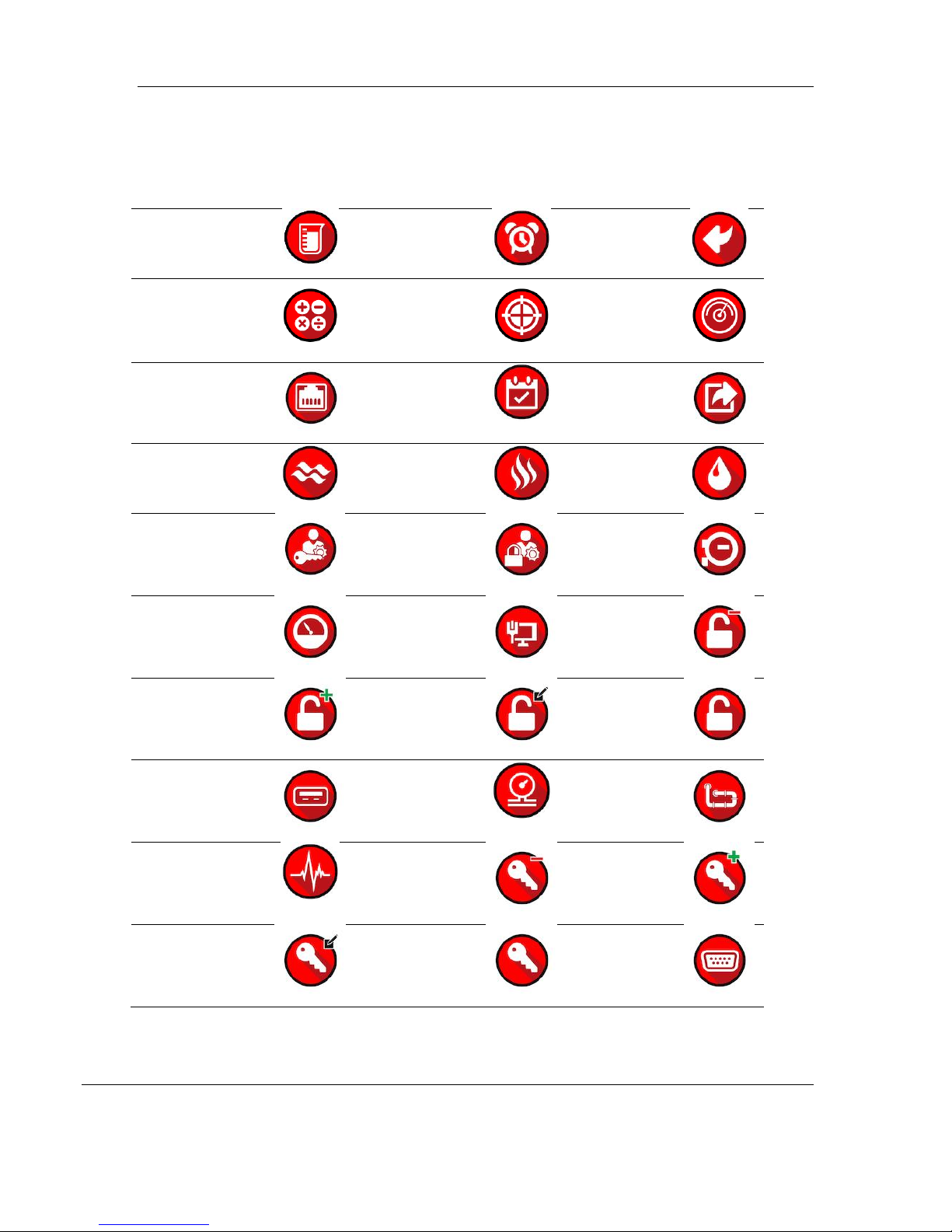
Configuration Aids
This manual contains icons within each section. Each icon represents a
relationship to the topic.
Accumulator
Alarm
Back
Calculate
Calibrate
Calibrate 2
Ethernet
Event
Export
Flow
Gas
Liquid
Login
Logout
Meter
Meter
Network
Delete
Permission
Add
Permission
Edit
Permission
Generic
Permission
Port
Pressure
Prover
Pulse
Delete Role
Add Role
Edit Role
Generic
Role
Serial
Connection

MVI56E-AFC ♦ Version 4.04 Before you Begin
ProSoft Technology, Inc. Page 15 of 149
October 2, 2018
Site
Stream
Temp
User
Delete User
Add User
Edit User
View
Delete
View
Add View
Edit View
Volume
The icons are used as visual cues to provide a hint of the type of information
contained within a section.

Before you Begin MVI56E-AFC ♦ Version 4.04
Page 16 of 149 ProSoft Technology, Inc.
October 2, 2018
Using the Modbus Dictionary
Important: Although this manual is continuously maintained to bring you the latest information, the
Modbus Dictionary contains the latest information on registers and dictionary sections. It is
recommended that you use the Modbus Dictionary to locate bank and register values to ensure
that you are looking at the latest information.
The Modbus dictionary provides a means to locate data anywhere in the module.
The dictionary allows you to select various data types from database regions. It
then displays Modbus bank and register values.

MVI56E-AFC ♦ Version 4.04 Before you Begin
ProSoft Technology, Inc. Page 17 of 149
October 2, 2018
You can use the Modbus Dictionary locally or while EAFC manager is directly
connected to the MVI56E-AFC. From the Source Configuration section, select
LOCAL if you are just running Modbus Dictionary locally or select ON-LINE if
connected to a module.
The Dictionary Section drop-down list allows you to select different types of data
from different sections of the module.
The Meter selection allows you to specify a specific meter in order to view only
information pertaining to the selected meter.
If selected, the SHOW BITS checkbox allows the bits to be displayed in the Bank &
Reg column.
The Search box allows you to search for specific data. The search is applied to
entries in the Description column and is case insensitive.

Before you Begin MVI56E-AFC ♦ Version 4.04
Page 18 of 149 ProSoft Technology, Inc.
October 2, 2018
Procedure
Ensure that you have a suitable project loaded, especially its version. This
ensures that dictionary items present for your module are available for display.
1 In EAFC Manager, select the PROJECT tab.
2 Select Modbus Dictionary, See Starting EAFC Manager for information on
setting your module type.
3 Select the SOURCE CONFIGURATION (Local or On-line).
4 Select the DICTIONARY SECTION from the drop-down list.
5 Select the METER stream.
6 Check the SHOW BITS checkbox to enable the display of individual bits.

MVI56E-AFC ♦ Version 4.04 Before you Begin
ProSoft Technology, Inc. Page 19 of 149
October 2, 2018
7 Click on the appropriate row.
8 Once a row is selected, additional information is displayed at the bottom of
the window.

Before you Begin MVI56E-AFC ♦ Version 4.04
Page 20 of 149 ProSoft Technology, Inc.
October 2, 2018
9 Observe the Bank and Reg information in the first column. This column may
contain a number of items with different representations.
In the first row, the first position indicates whether the register is a Holding
Register (H-) or an Input Register (I-), the second position represents the
register (8000). The third position indicates high order bytes (H), low order
bytes (L), multiple registers (*), and a plus sign (+) indicates that there are
two registers (used for 32-bit quantities, i.e., long integer and floating point
elements).
If SHOW BITS is checked, a number in the third position is the bit number. For
Datum Type “String”, each register holds two characters.
Other manuals for MVI56E-AFC
1
Table of contents


